


 internet
Similar presentations:


")


Spanning Tree. Lecture 4
1.
ATP. Lecture 4Spanning
Tree
1
2.
Objectives1. Configure Rapid
Spanning Tree Protocol
(RSTP)
2. Multiple Spanning Tree
Protocol (MSTP)
2
3.
Spanning Tree1. Configure Rapid Spanning Tree
Protocol (RSTP)
3
4.
Issues adding redundant links to the topologyNetworks deliver critical services to users. Failure of a network link
may make the network unavailable to users, resulting in lost time
or revenue. To protect a network against these failures, you can
install redundant links.
Redundant links help to ensure that a path continues to exist across
the network even if one link or even one switch fails.
4
5.
Issues adding redundant links to the topologyHowever, simply adding redundant physical
links does not ensure that the switches can
use those links correctly.
Adding redundant Layer 2 links without a
protocol to manage the links results in
network loops.
To function properly, an Ethernet network
must have only one active pathway between
any two devices.
5
6.
Issues adding redundant links to the topology6
7.
Overview of STP• The original standard
Spanning Tree
Several
Protocol (STP)
STP
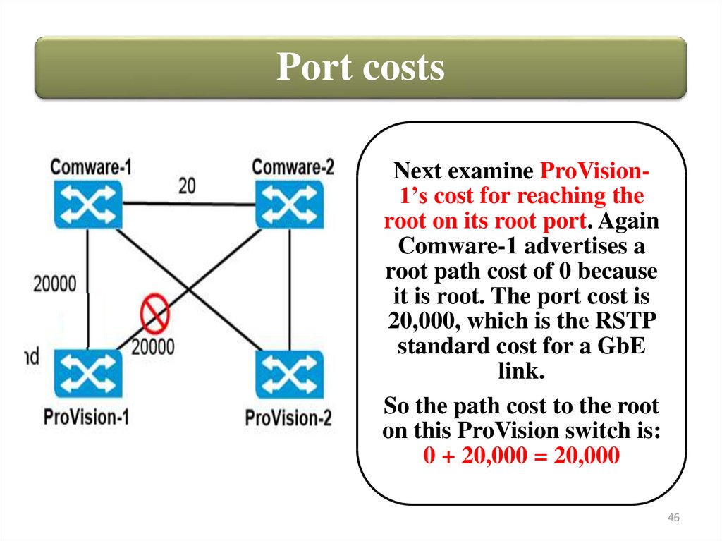
• Rapid Spanning Tree
versions
Protocol (RSTP)
exist:
• Multiple Spanning
Tree Protocol (MSTP)
7
8.
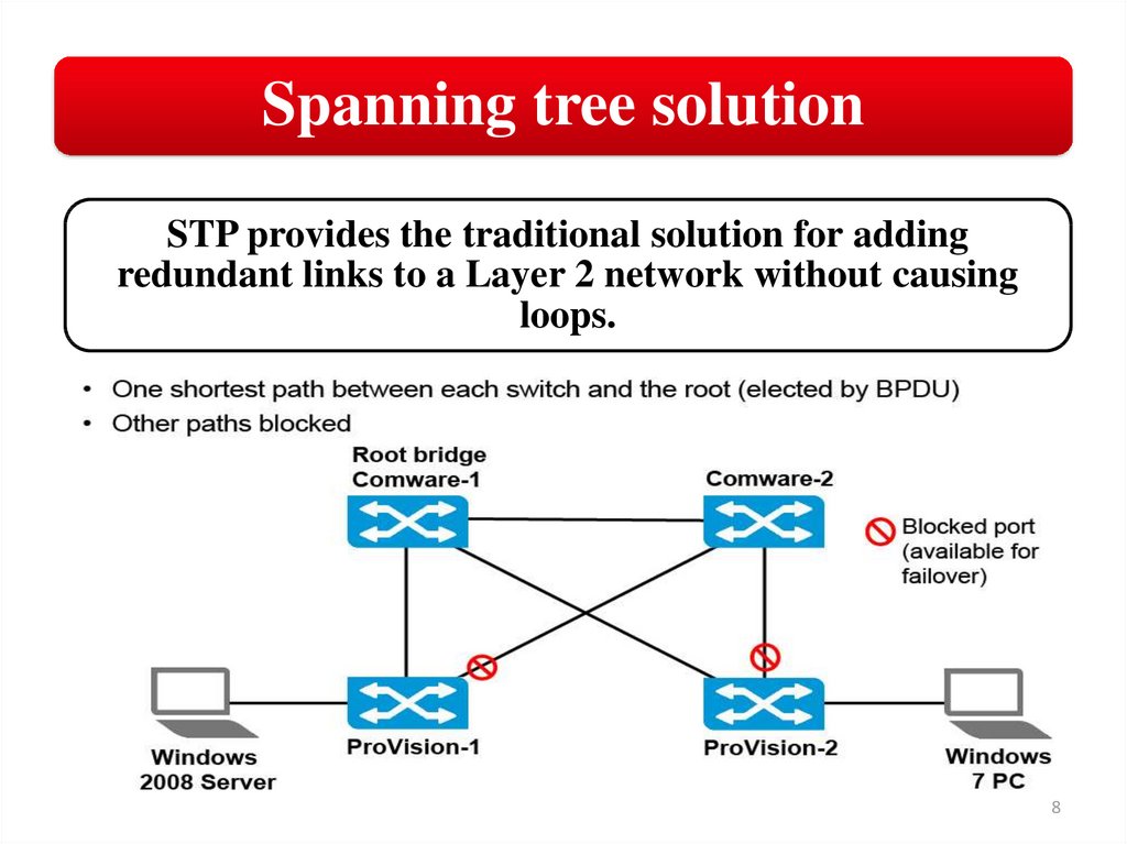
Spanning tree solutionSTP provides the traditional solution for adding
redundant links to a Layer 2 network without causing
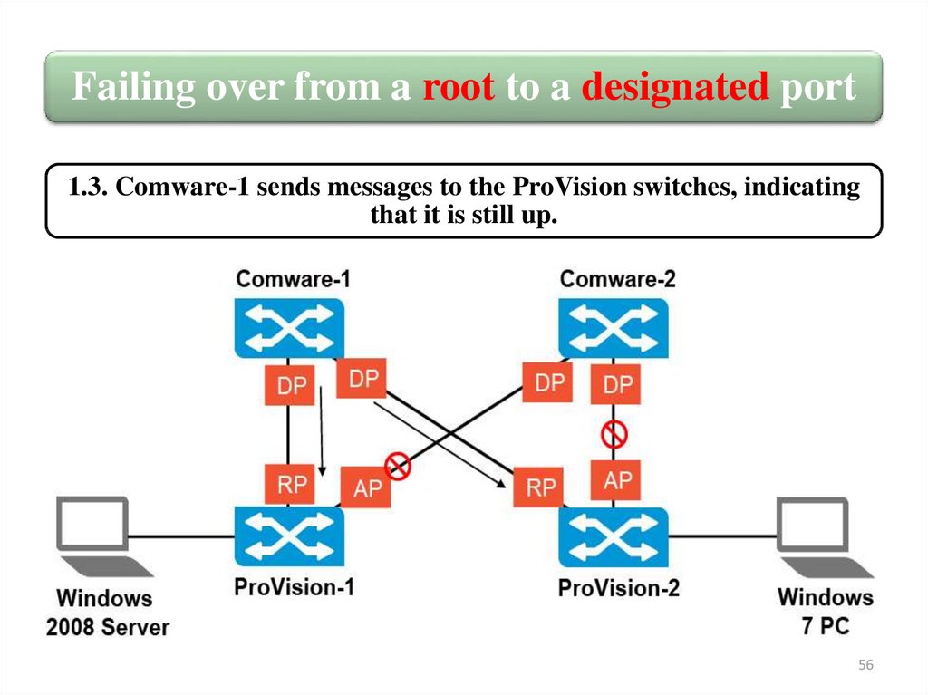
loops.
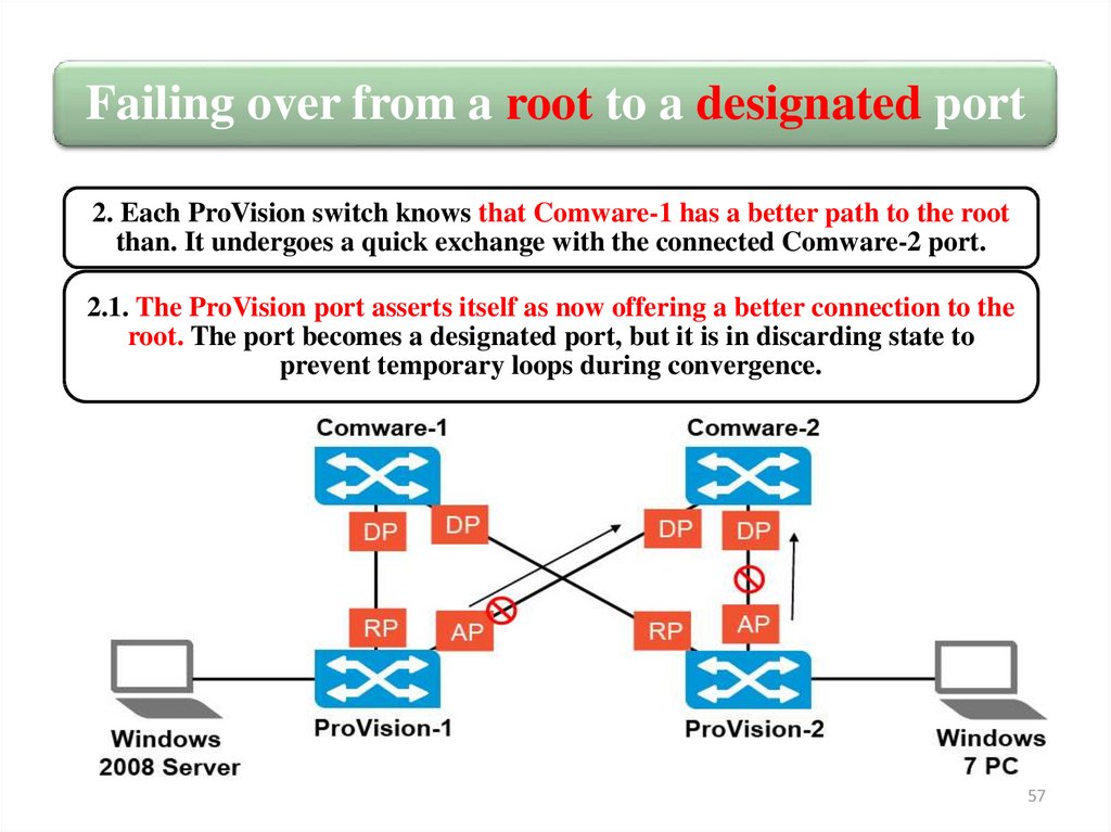
8
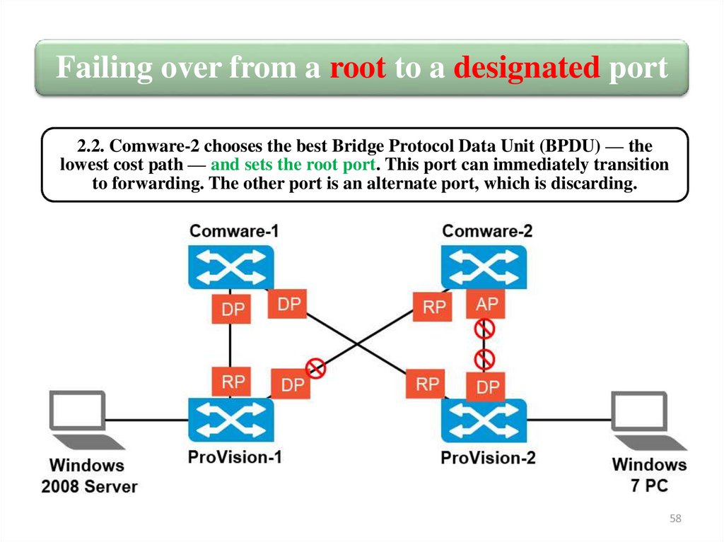
9.
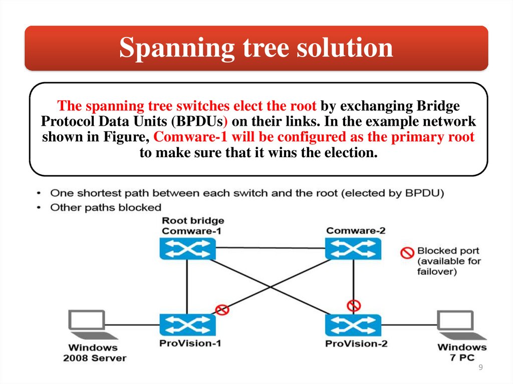
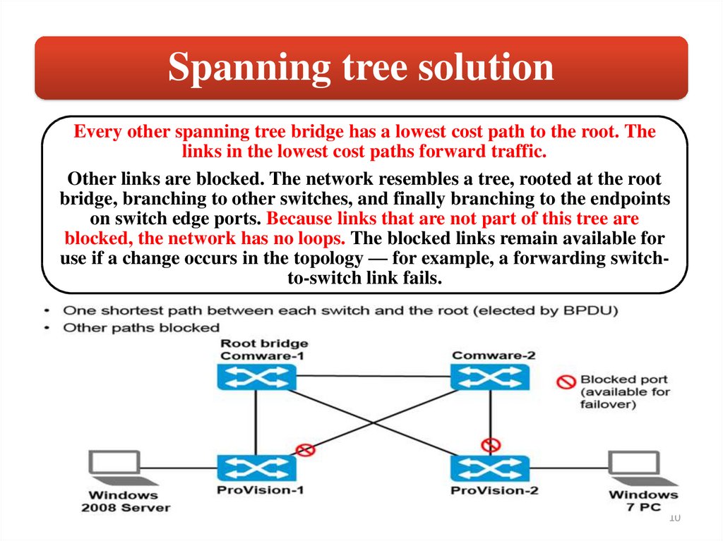
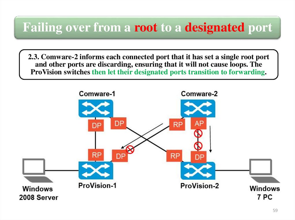
Spanning tree solutionThe spanning tree switches elect the root by exchanging Bridge
Protocol Data Units (BPDUs) on their links. In the example network
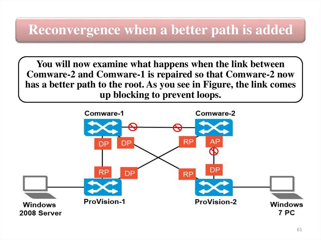
shown in Figure, Comware-1 will be configured as the primary root
to make sure that it wins the election.
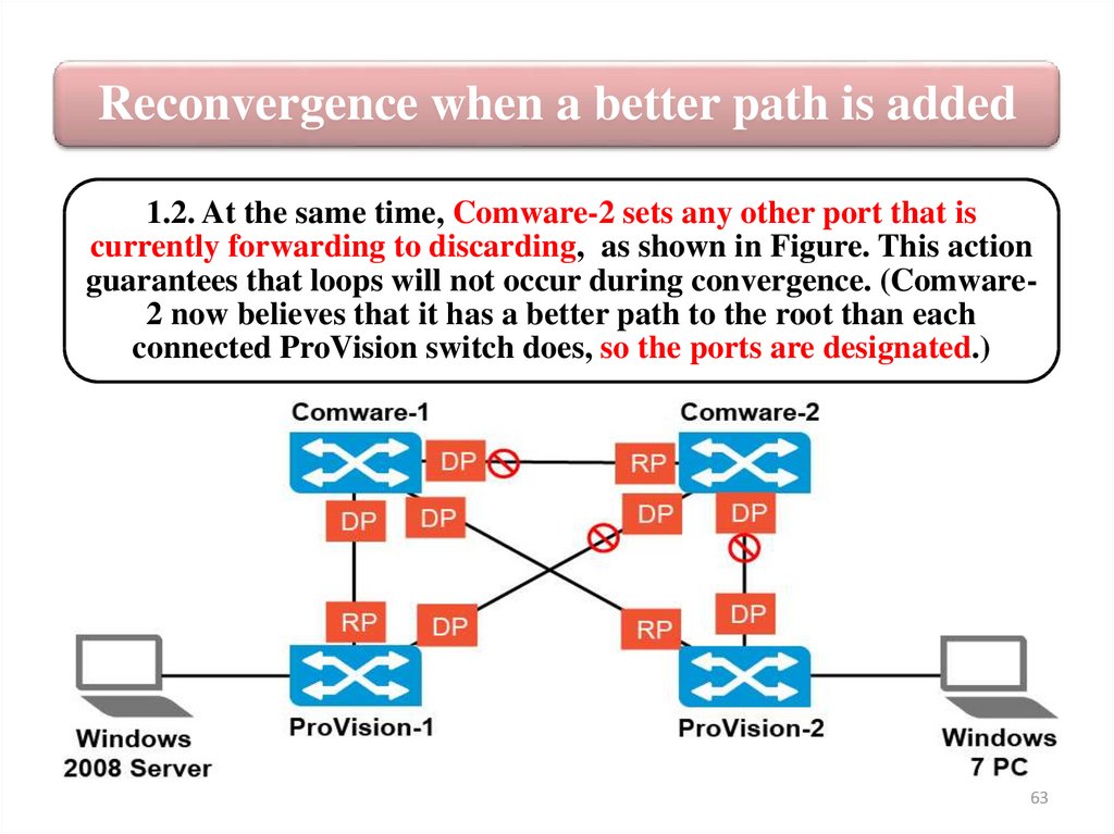
9
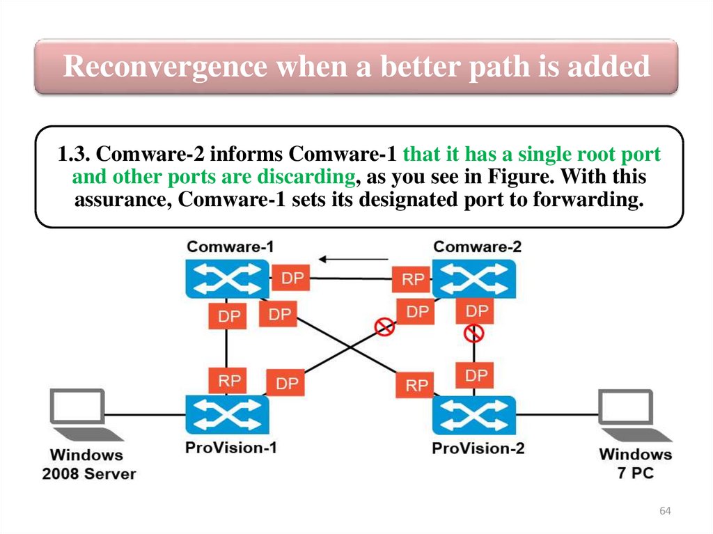
10.
Spanning tree solutionEvery other spanning tree bridge has a lowest cost path to the root. The
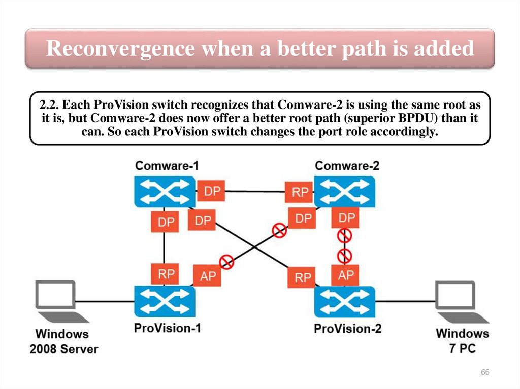
links in the lowest cost paths forward traffic.
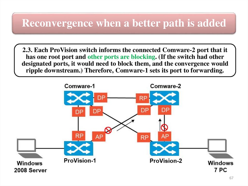
Other links are blocked. The network resembles a tree, rooted at the root
bridge, branching to other switches, and finally branching to the endpoints
on switch edge ports. Because links that are not part of this tree are
blocked, the network has no loops. The blocked links remain available for
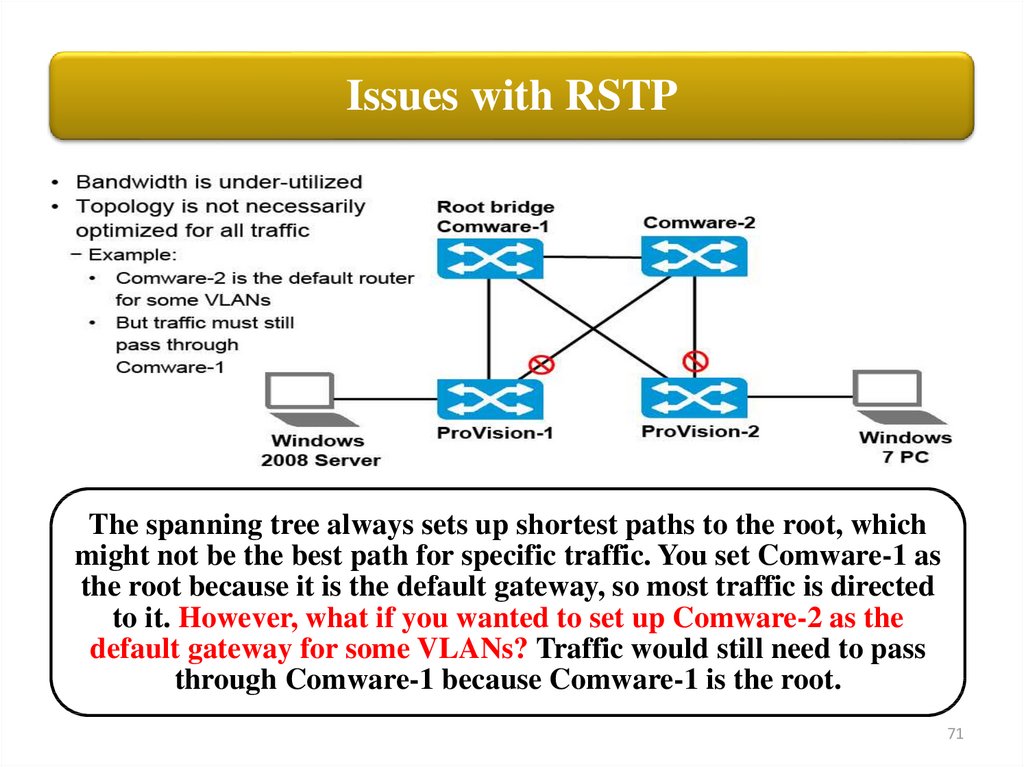
use if a change occurs in the topology — for example, a forwarding switchto-switch link fails.
10
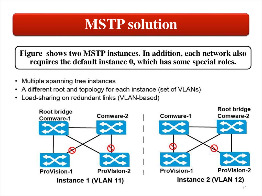
11.
The original standard Spanning TreeProtocol (STP)
The original standard, STP, is defined in 802.1D. This
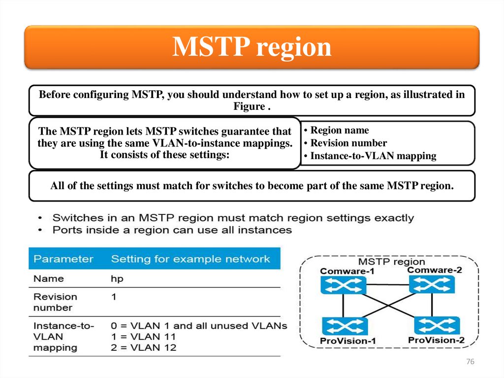
standard defined the basic behaviors still used in
spanning tree, such as electing a root bridge, calculating
the best path to that bridge, and blocking alternate
paths.
However, STP was designed in a time when a minute or
so for convergence was acceptable. It requires ports to
move through several port states, each with a relatively
long (10–20 seconds) wait time, before the ports can
start forwarding. Any change in the topology can force
ports to progress slowly through these states again.
11
12.
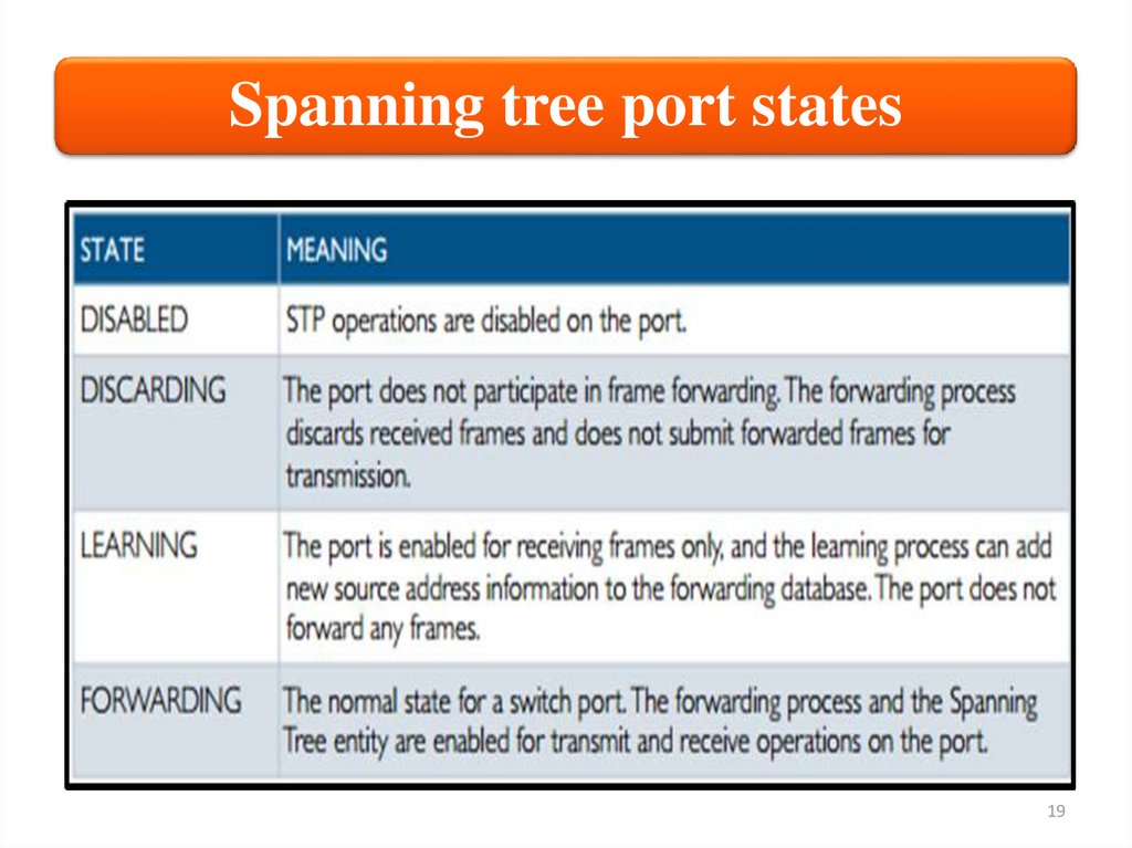
The original standard Spanning TreeProtocol (STP)
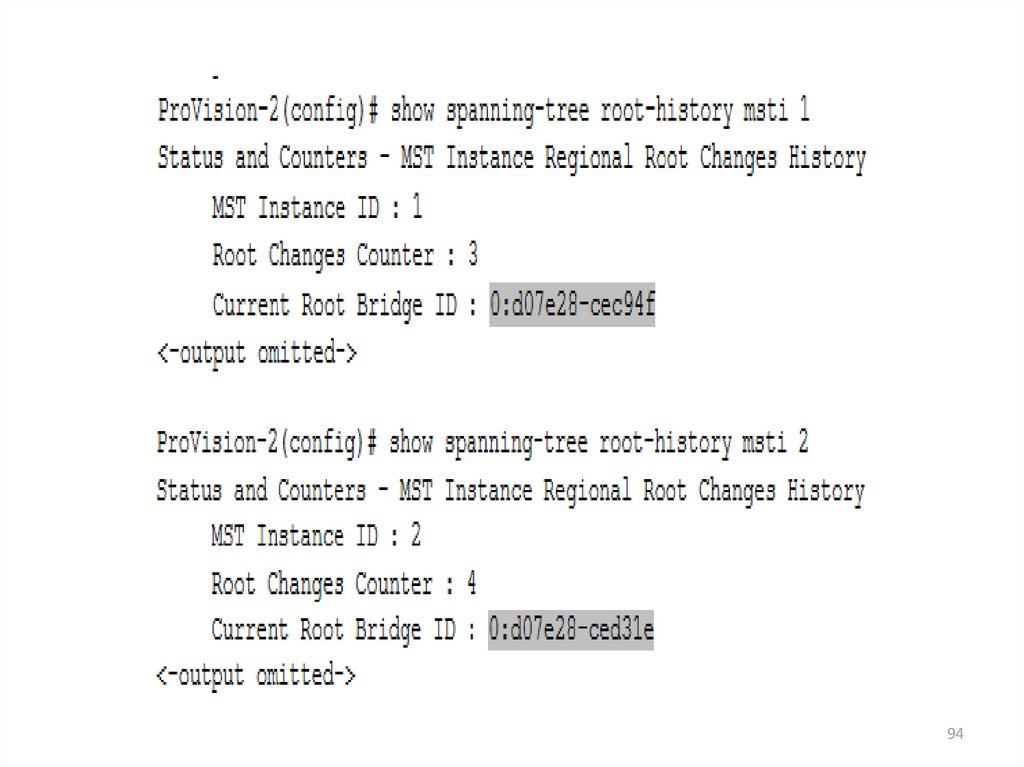
Summary of the port states in STP
Disabled
STP is disabled by default
Blocking
The port drops all the data
and listens to BPDUs
Listening
The port drops all the data,
listens to BPDUs and it will
be used in the active
topology
Learning
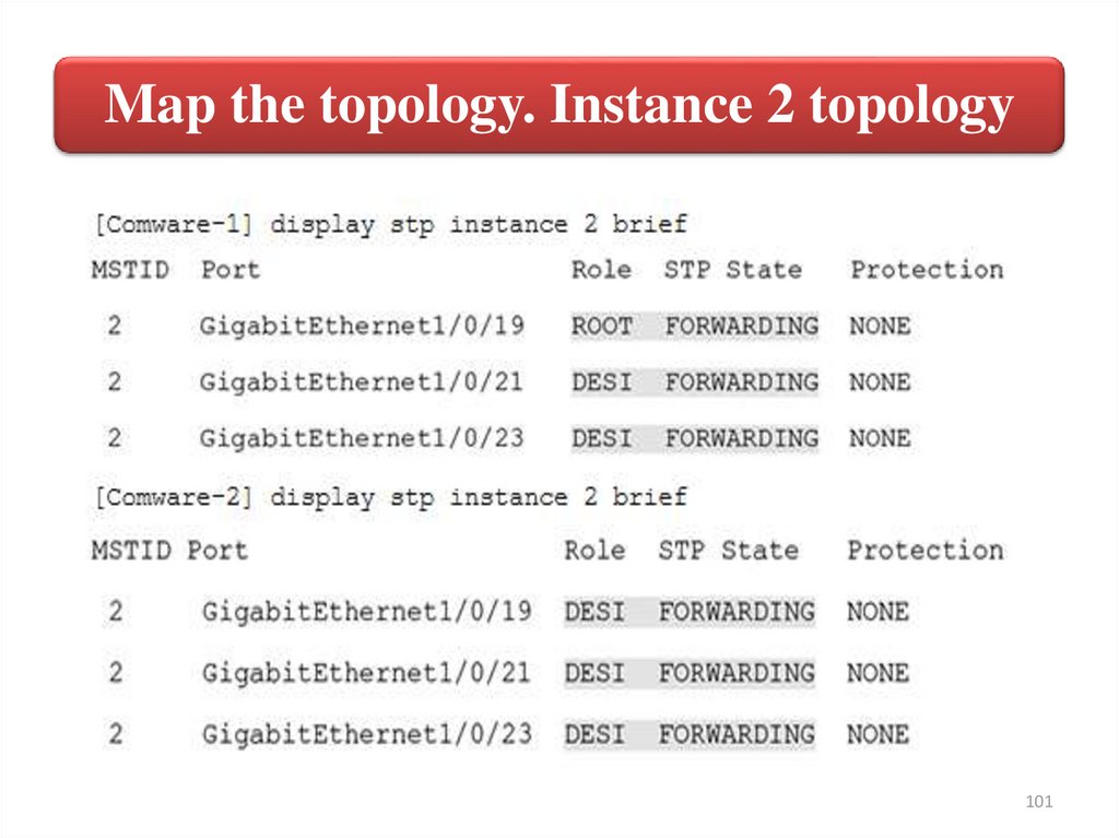
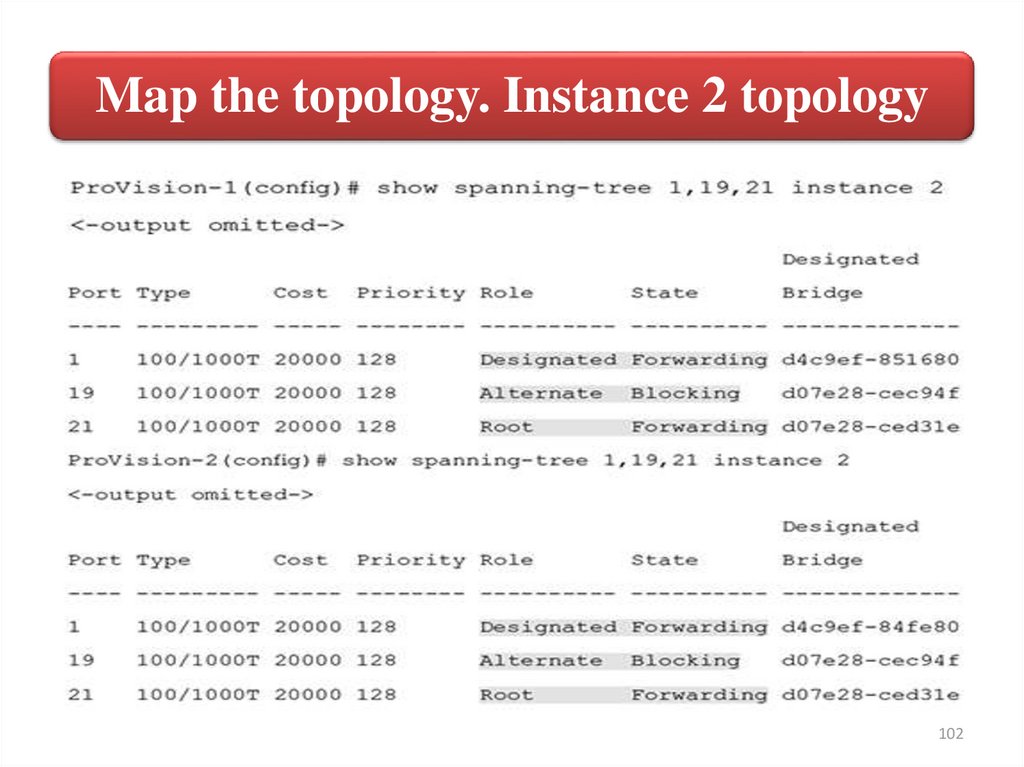
The port drops all the data,
listens to BPDUs and it is
learning MAC addresses
Forwarding
The port forwards data and
it’s learning MAC addresses
12
13.
Rapid Spanning Tree Protocol (RSTP)As network connectivity became more crucial, companies
could no longer tolerate such long convergence times when
any topology change occurred. RSTP, 802.1w, was developed
in 1998 to speed convergence.
In 2004, RSTP was merged into the 802.1D, superseding STP.
Therefore, this chapter focuses on how RSTP functions over
STP.
RSTP has
better
convergence
than STP due to
these factors:
• Direct and indirect failure detection and
recovery
• Faster transition between port roles
• Point-to-point link designation
• Edge port designation
13
14.
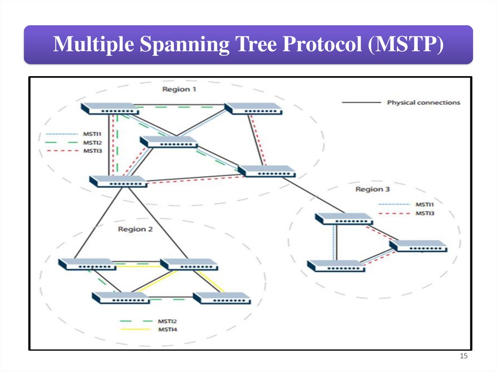
Multiple Spanning Tree Protocol (MSTP)An extension to RSTP, known as Multiple Spanning
Tree Protocol (MSTP), allows for a separate STP
configuration for each VLAN group in the network
Multiple Spanning Tree Protocol (MSTP) is a protocol
that allows groups of VLANs to have different spanning
tree topologies within an Ethernet Network. MSTP was
introduced in IEEE 802.1s to use multiple spanning
trees, providing for traffic belonging to different VLANs
to flow over potentially different paths within the virtual
bridged LAN. This allows for better load balancing and
more efficient use of available resources.
14
15.
Multiple Spanning Tree Protocol (MSTP)15
16.
In this study guide youwill begin by learning how
to set up an IEEE 802.1w
Rapid Spanning Tree
Protocol (RSTP) solution
16
17.
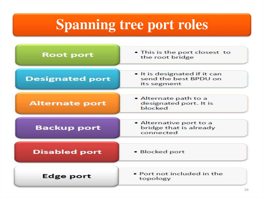
Spanning tree port roles and statesThe RSTP algorithm provides for a faster
recovery of connectivity following the failure of a
bridge, bridge port, or a link. RSTP provides
rapid recovery by including port roles in the
computation of port states, and by allowing
neighboring bridges to explicitly acknowledge
signals on a point-to-point link that indicate that a
port wants to enter the forwarding mode.
RSTP adds new bridge port roles in order to
speed convergence following a link failure. The
port roles and states are summarized in Table on
the next slides
17
18.
Spanning tree port roles18
19.
Spanning tree port states19
20.
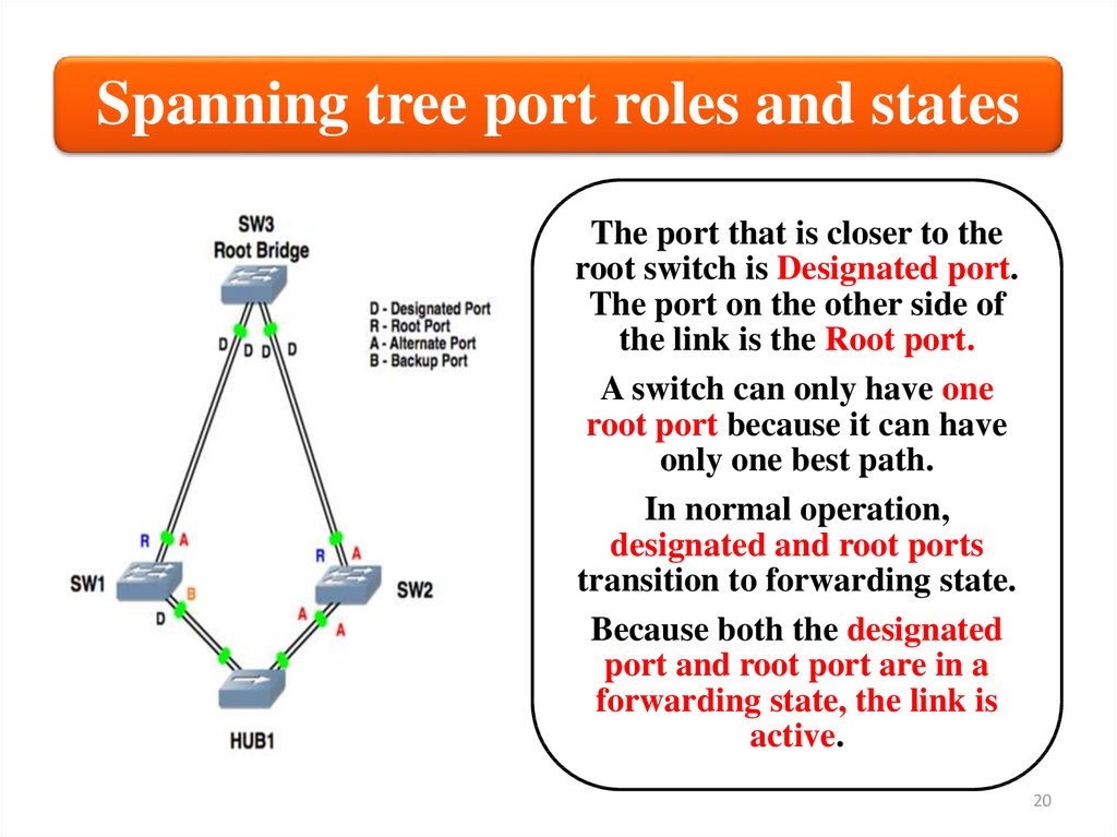
Spanning tree port roles and statesThe port that is closer to the
root switch is Designated port.
The port on the other side of
the link is the Root port.
A switch can only have one
root port because it can have
only one best path.
In normal operation,
designated and root ports
transition to forwarding state.
Because both the designated
port and root port are in a
forwarding state, the link is
active.
20
21.
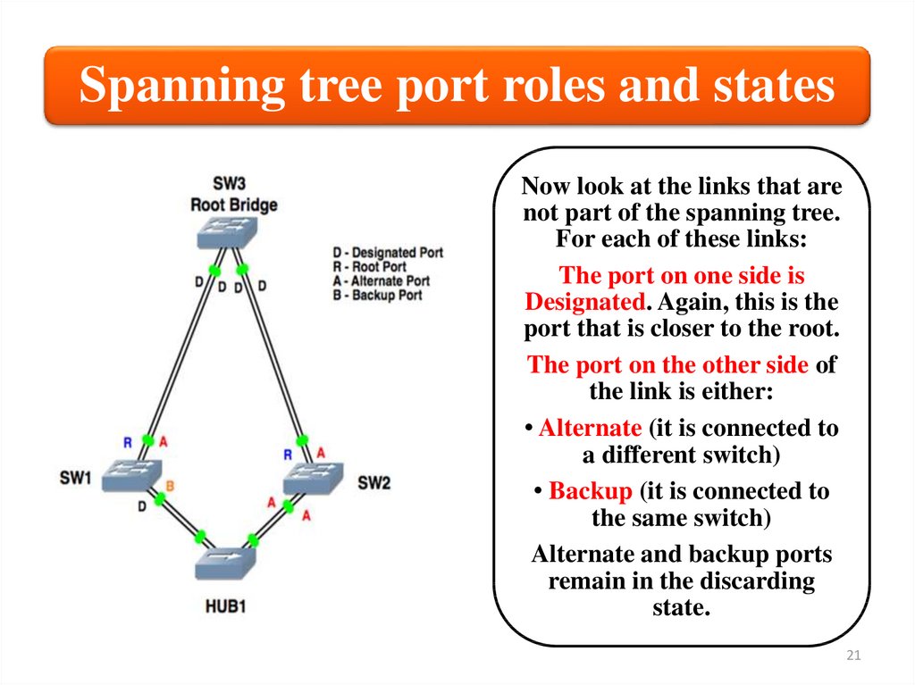
Spanning tree port roles and statesNow look at the links that are
not part of the spanning tree.
For each of these links:
The port on one side is
Designated. Again, this is the
port that is closer to the root.
The port on the other side of
the link is either:
• Alternate (it is connected to
a different switch)
• Backup (it is connected to
the same switch)
Alternate and backup ports
remain in the discarding
state.
21
22.
Configuration example: RSTPIn this section, you will learn how to set up RSTP on HP switches. The
instructions provided are based on the example network, which is using
the settings shown in Figure. Starting network configuration:
22
23.
Configuration example: RSTPYou will configure RSTP on each of the switches in the
example network, changing the network topology as shown
in Figure. Add redundant links:
23
24.
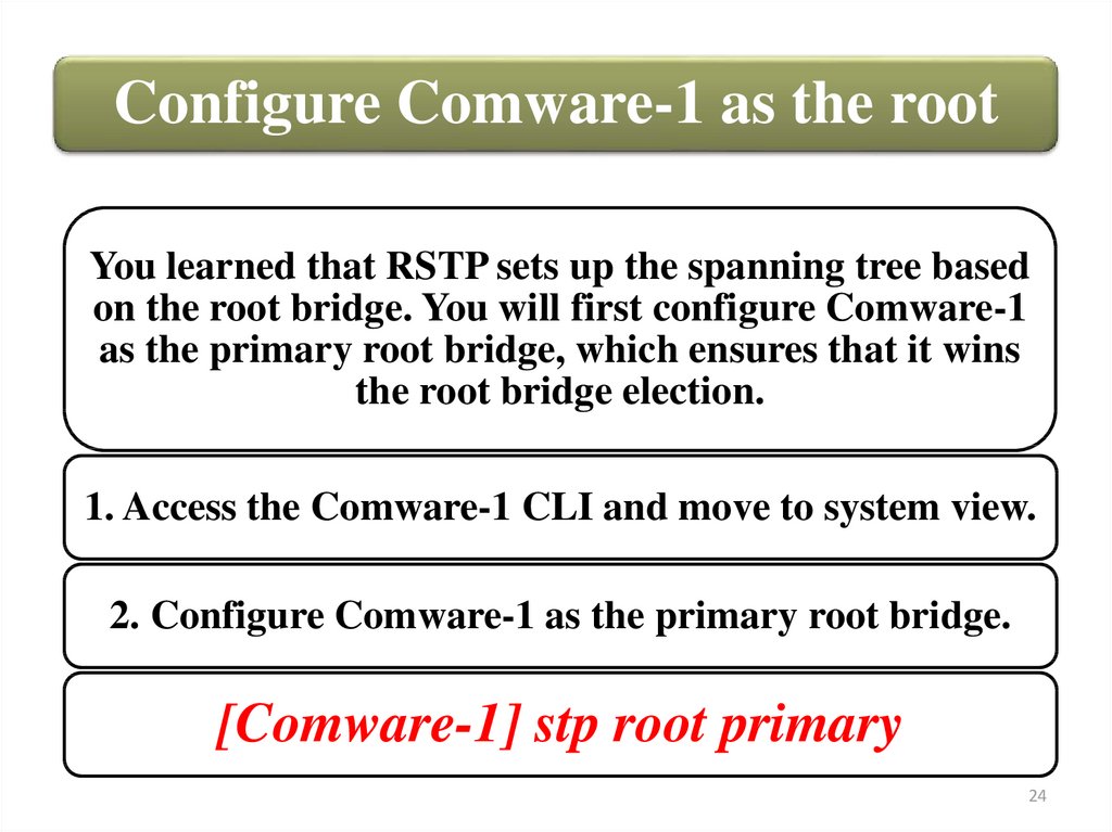
Configure Comware-1 as the rootYou learned that RSTP sets up the spanning tree based
on the root bridge. You will first configure Comware-1
as the primary root bridge, which ensures that it wins
the root bridge election.
1. Access the Comware-1 CLI and move to system view.
2. Configure Comware-1 as the primary root bridge.
[Comware-1] stp root primary
24
25.
Enable spanning tree on each switchYou will enable spanning tree on the HP switches. Recall that STP is disabled by
default on both the Comware and ProVision switches.
1. Enable spanning tree on Comware-1.
[Comware-1] stp enable
2. Access the Comware-2 CLI and move to system view.
3. Enable spanning tree.
[Comware-2] stp enable
4. Access the ProVision-1 CLI and move to global configuration mode.
5. Enable spanning tree.
ProVision-1(config)# spanning-tree
6. Access the ProVision-2 CLI and move to global configuration mode.
7. Enable spanning tree.
ProVision-2(config)# spanning-tree
25
26.
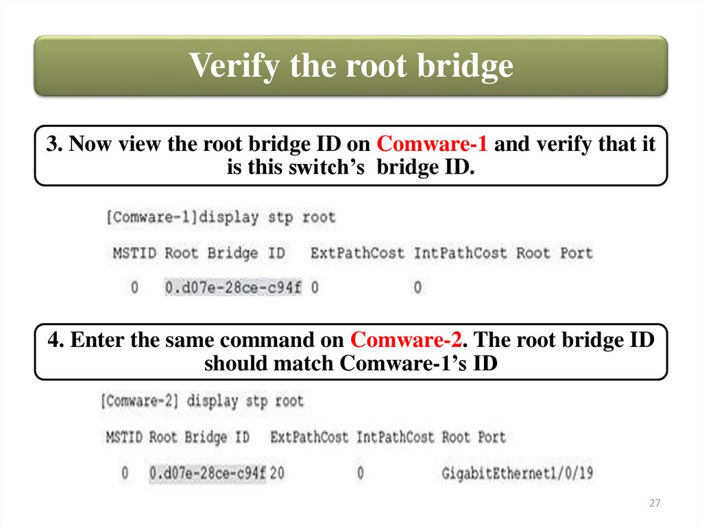
Verify the root bridgeYou will now verify that Comware-1 has been elected the root
bridge, as desired.
1. Enter the following command on the Comware-1 switch. Find the
bridge ID, which is listed next to CIST Bridge.
2. Record Comware-1’s bridge ID – 0.d07e-28ce-c94f
26
27.
Verify the root bridge3. Now view the root bridge ID on Comware-1 and verify that it
is this switch’s bridge ID.
4. Enter the same command on Comware-2. The root bridge ID
should match Comware-1’s ID
27
28.
Verify the root bridge5. Enter the following command on ProVision-1 and verify that
the root is Comware-1.
The Common Spanning Tree (CST) includes all spanning tree
bridges.
28
29.
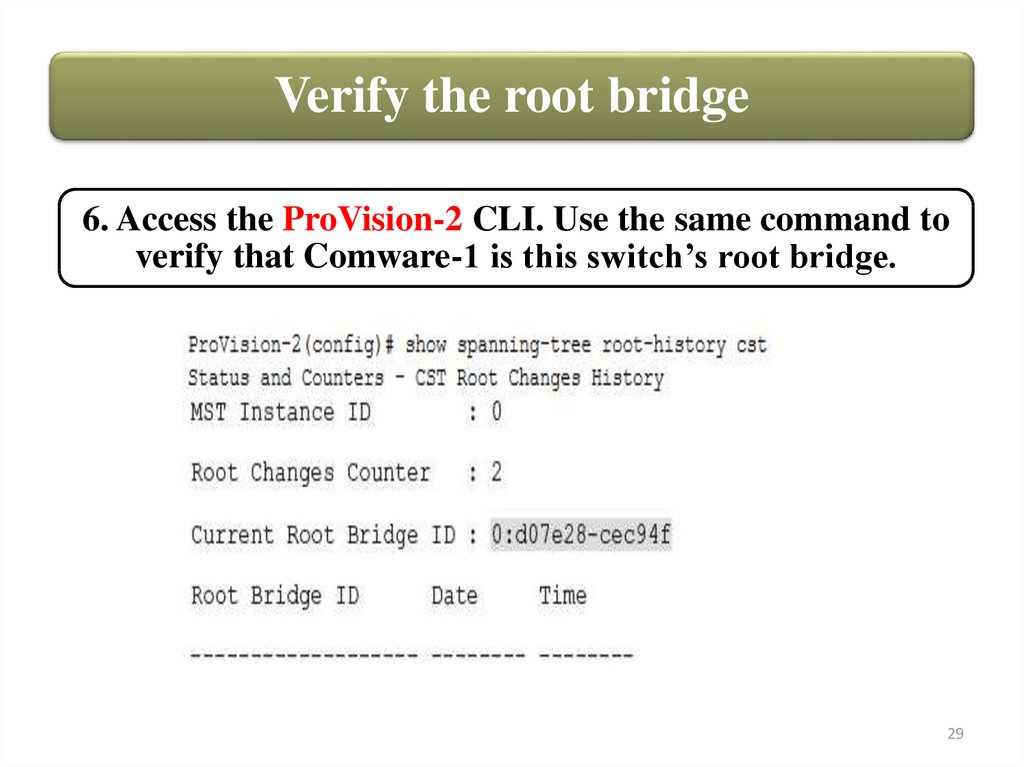
Verify the root bridge6. Access the ProVision-2 CLI. Use the same command to
verify that Comware-1 is this switch’s root bridge.
29
30.
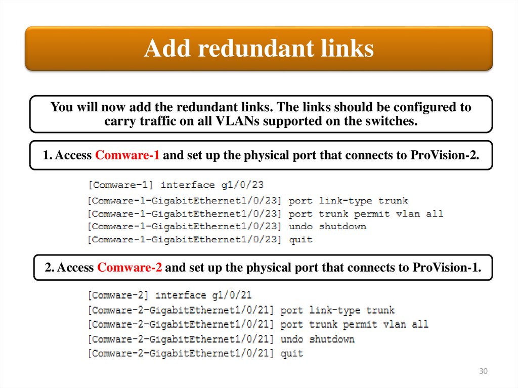
Add redundant linksYou will now add the redundant links. The links should be configured to
carry traffic on all VLANs supported on the switches.
1. Access Comware-1 and set up the physical port that connects to ProVision-2.
2. Access Comware-2 and set up the physical port that connects to ProVision-1.
30
31.
Add redundant links3, 4. Access ProVision-1 and set up the physical port that connects to
Comware-2.
5. If necessary, establish the physical link between
ProVision-1 and Comware-2.
6. Verify that the link has come up.
31
32.
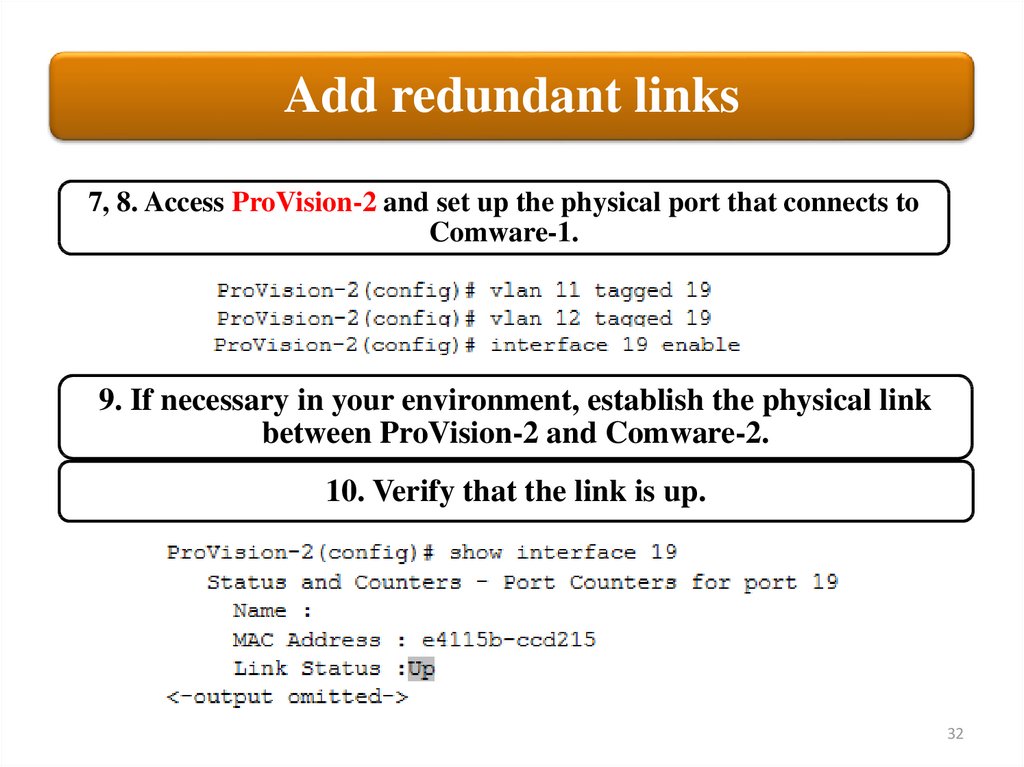
Add redundant links7, 8. Access ProVision-2 and set up the physical port that connects to
Comware-1.
9. If necessary in your environment, establish the physical link
between ProVision-2 and Comware-2.
10. Verify that the link is up.
32
33.
Add redundant links11. Access the Comware-1 CLI.
12. Quickly validate that the port connections are correct by examining
the LLDP neighbor table.
33
34.
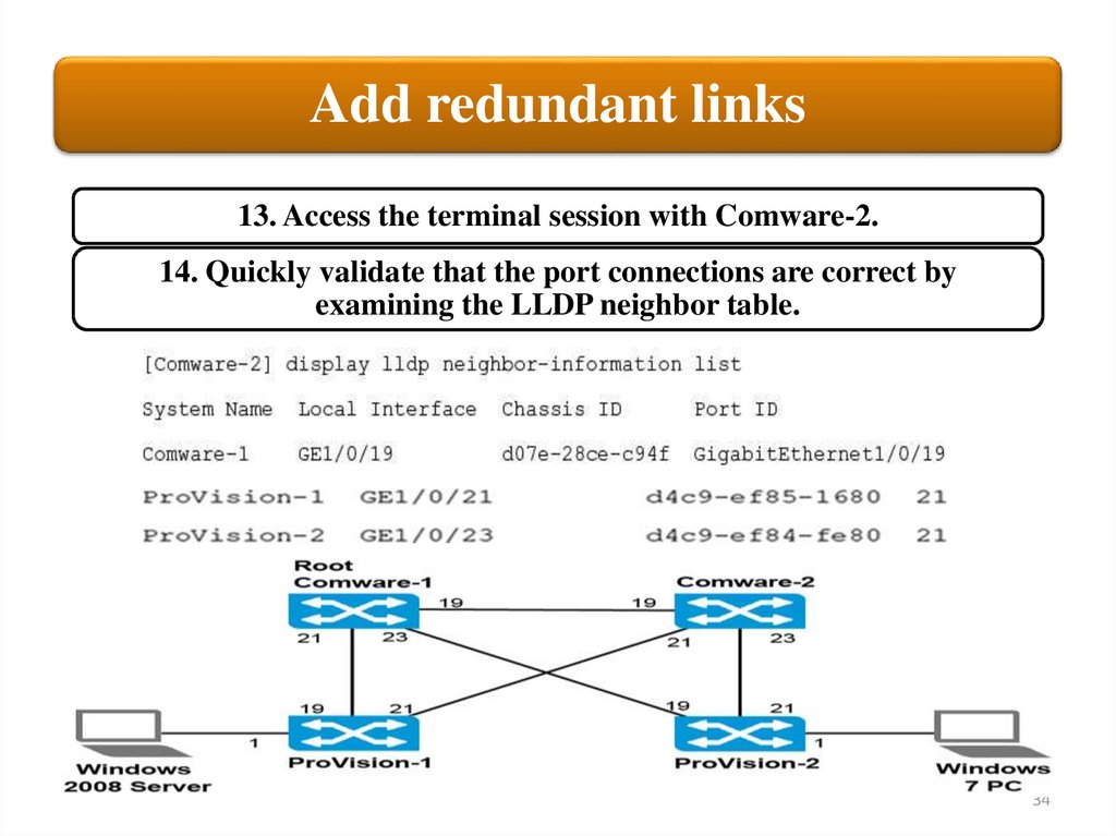
Add redundant links13. Access the terminal session with Comware-2.
14. Quickly validate that the port connections are correct by
examining the LLDP neighbor table.
34
35.
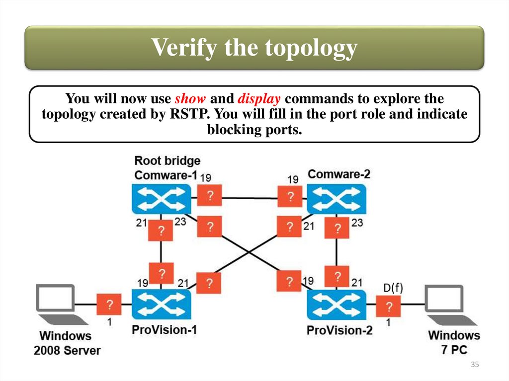
Verify the topologyYou will now use show and display commands to explore the
topology created by RSTP. You will fill in the port role and indicate
blocking ports.
35
36.
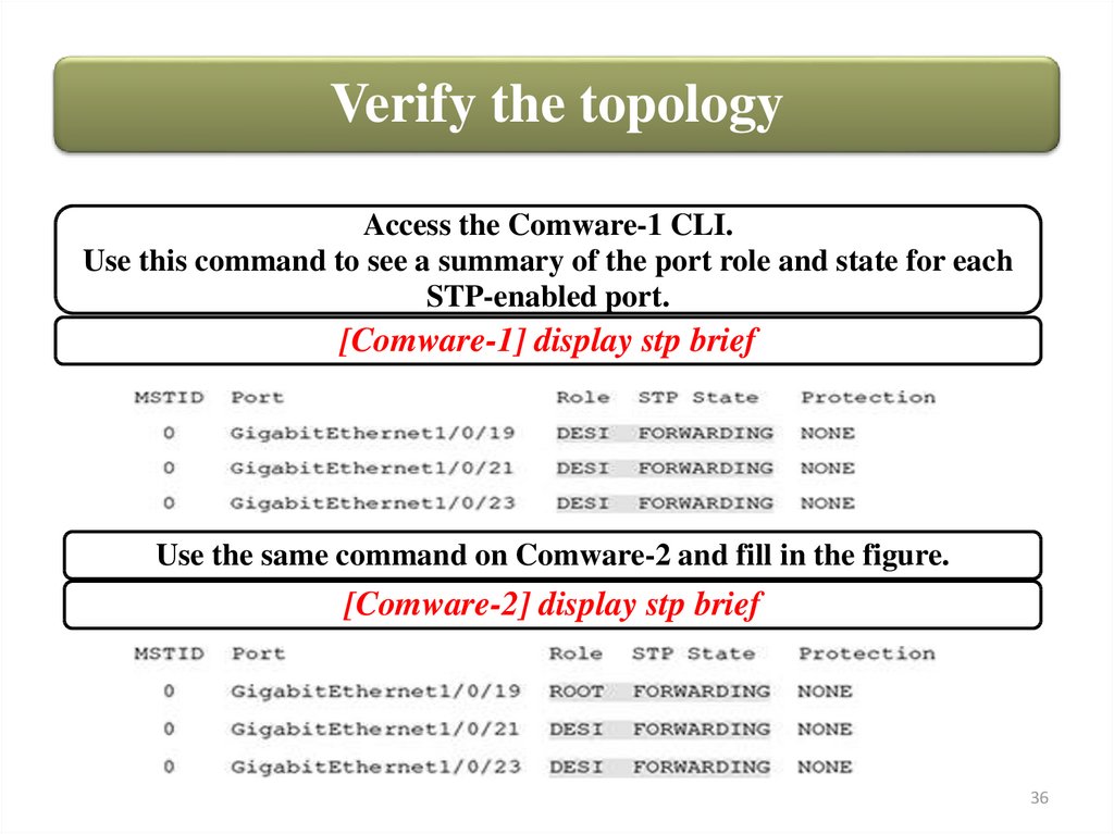
Verify the topologyAccess the Comware-1 CLI.
Use this command to see a summary of the port role and state for each
STP-enabled port.
[Comware-1] display stp brief
Use the same command on Comware-2 and fill in the figure.
[Comware-2] display stp brief
36
37.
Verify the topologyAccess the ProVision-1 CLI. Use the following command to view the port
state on desired interfaces.
Access the ProVision-2 CLI.
37
38.
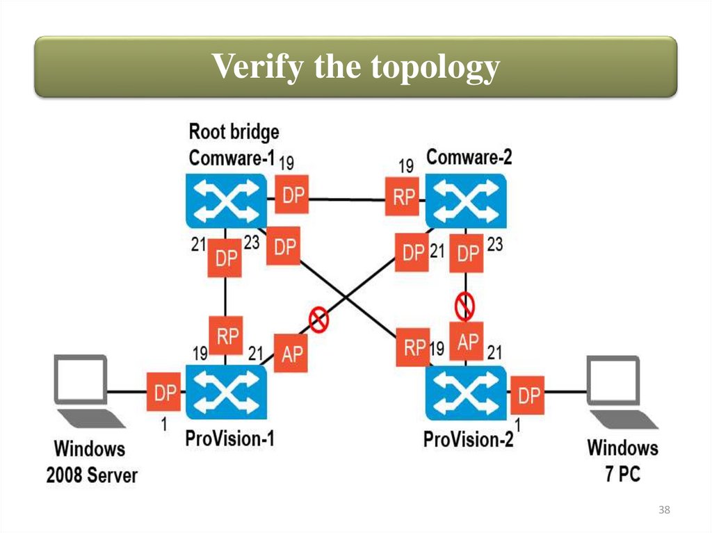
Verify the topology38
39.
Root electionYou will now examine in more detail how a root bridge is elected. In
the example configuration, the stp root primary command was
used on Comware-1 to ensure that it won the election.
What did this command actually do? It set the switch’s spanning tree
priority value to 0.
A lower priority value gives a higher priority for being elected root, so
Comware-1 was elected root.
39
40.
Root electionIf Comware-1 failed, leaving only active switches with the default priority. It
is actually difficult to predict which switch becomes root in this case.
To understand why, you need to understand that switches do not actually use the
priority alone to elect the root. They actually use their bridge ID for the election.
40
41.
Root electionThe bridge ID is: • Priority + system ID (MAC address)
Priority value
Step
Comware root command
Priority value
Step
0
0
root primary
32768
8
4096
1
root secondary
36864
9
8092
2
40960
10
12288
3
45056
11
16384
4
49152
12
20480
5
53248
13
24576
6
57344
14
28672
7
61440
15
The priority value is more significant, so it affects the election most. However,
when multiple switches have the same priority, the switch with the lowest MAC
address becomes root.
41
42.
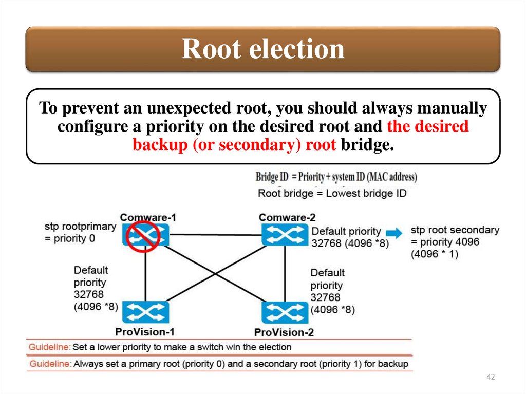
Root electionTo prevent an unexpected root, you should always manually
configure a priority on the desired root and the desired
backup (or secondary) root bridge.
42
43.
Port costsSometimes links have different bandwidth, so the ports have different
costs. Sometimes switches are using different ways to set the port cost.
For example, look at both Comware-2’s and ProVision-1’s link to the root.
Comware-2 has a port cost of 20, and ProVision-1 has a cost of 20,000—
even though both switches have a GbE link. The difference occurs because
the two switches are using different path cost standards.
43
44.
Port costsThe cost for
reaching the root
on any port is:
• The cost advertised in the
BPDU + The port cost
The port cost derives from the bandwidth on the port, as
defined by the spanning tree standard. Comware switches,
however, by default use a proprietary port cost stetting.
DEFAULT PORT COSTS
44
45.
Port costsLook at the cost for reaching
the root on Comware-2’s root
port. The cost advertised in the
BPDU is 0. Comware-1 is the
root, so it does not have a cost
for reaching the root. The port
cost is 20.
So the path cost is: 0 + 20 = 20.
This is Comware-2’s best path
to the root, so this becomes its
root path cost. Comware-2
advertises this cost in BPDUs
that it sends on any designated
port.
45
46.
Port costsNext examine ProVision1’s cost for reaching the
root on its root port. Again
Comware-1 advertises a
root path cost of 0 because
it is root. The port cost is
20,000, which is the RSTP
standard cost for a GbE
link.
So the path cost to the root
on this ProVision switch is:
0 + 20,000 = 20,000
46
47.
Port costsNow look at the path cost on
ProVision-1’s alternate port.
Comware-2, as you saw earlier,
advertises a root path cost of 20.
The port cost is 20,000.
Therefore, the path cost to the
root is: 20 + 20,000 = 20,020.
This cost is higher than the cost
on the root port, which is exactly
why the first port is the root port
and the second one is the
alternate port. ProVision-1 has a
root path cost of 20,000, which is
what it would advertise to any
downstream devices.
47
48.
Port costsIn the example network topology, you did not
experience any negative effects from the discrepancy
between the port costs on the Comware and
ProVision switches. However, in a larger topology
with more links of varying bandwidths, the
discrepancy could cause issues. As a best practice,
you should set consistent costs on all switches —
generally, you should use the standard RSTP costs.
ProVision switches use these costs by default.
The Comware switches use this command:
stp pathcost dot1t.
48
49.
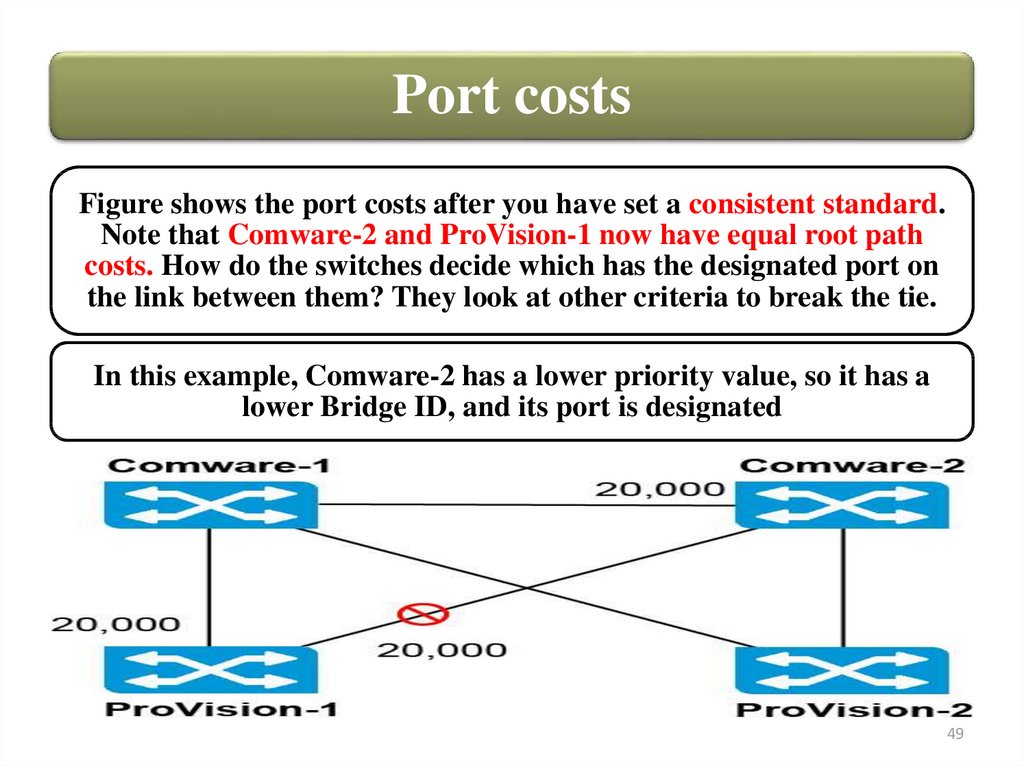
Port costsFigure shows the port costs after you have set a consistent standard.
Note that Comware-2 and ProVision-1 now have equal root path
costs. How do the switches decide which has the designated port on
the link between them? They look at other criteria to break the tie.
In this example, Comware-2 has a lower priority value, so it has a
lower Bridge ID, and its port is designated
49
50.
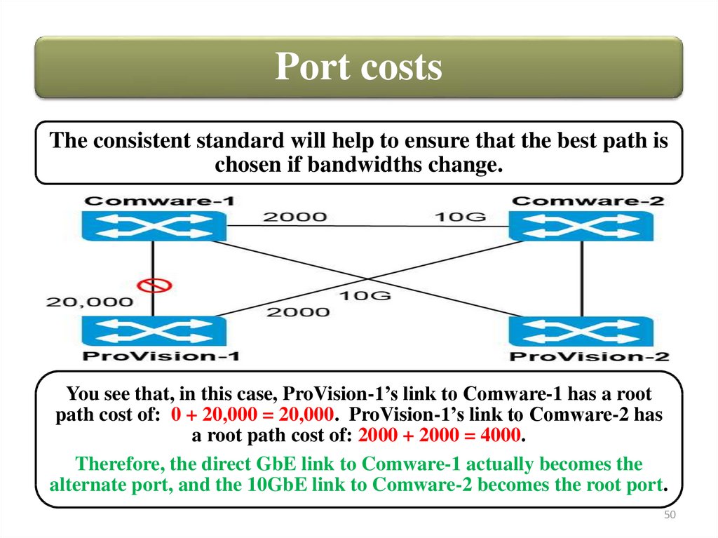
Port costsThe consistent standard will help to ensure that the best path is
chosen if bandwidths change.
You see that, in this case, ProVision-1’s link to Comware-1 has a root
path cost of: 0 + 20,000 = 20,000. ProVision-1’s link to Comware-2 has
a root path cost of: 2000 + 2000 = 4000.
Therefore, the direct GbE link to Comware-1 actually becomes the
alternate port, and the 10GbE link to Comware-2 becomes the root port.
50
51.
Failing over from a root to an alternate portFirst you will examine a scenario in which ProVision-1 loses its active link to
Comware-1 and must failover to its alternate link through Comware-1.
51
52.
Failing over from a root to an alternate portAs soon as ProVision-1 detects that its root port is down, it changes its
alternate port to a root port, which is immediately set to the forwarding
state.
The convergence takes under a second. Event messages on Comware-1 and
Comware-2 also indicate that ProVision-1 sends a topology change
message to update the root about the change.
52
53.
Failing over from a root to a designated portNext you will examine a scenario in which Comware-2 loses
its active link to Comware-1
53
54.
Failing over from a root to a designated portThe convergence in this case is a bit more
complicated. Comware-2 must transition one of its
designated ports to a root port. It must do so without
introducing temporary loops due to the convergence
process.
Several events occur when Comware-2 detects that it has lost its
root port:
1. It sends a Bridge Protocol Data Unit (BPDU) with a topology
change indication on each of its designated ports.
1.1. This Bridge Protocol Data Unit (BPDU) indicates that
Comware-2 is now the root. (It has lost contact with the root, and
it believes that it has the best priority.)
54
55.
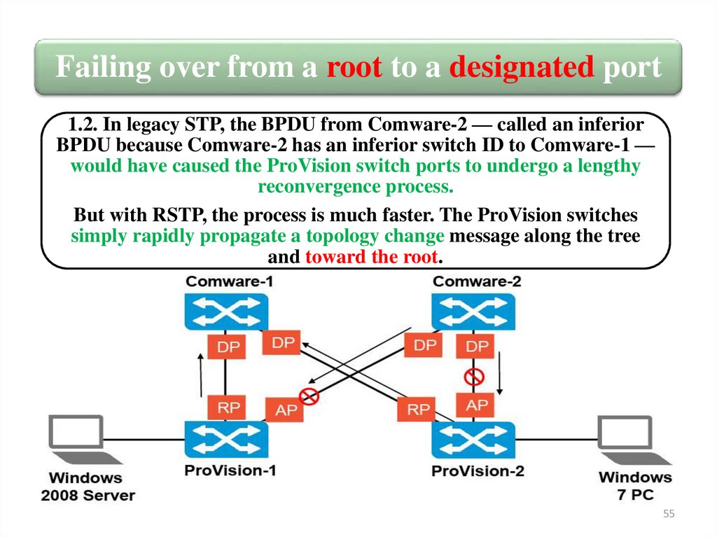
Failing over from a root to a designated port1.2. In legacy STP, the BPDU from Comware-2 — called an inferior
BPDU because Comware-2 has an inferior switch ID to Comware-1 —
would have caused the ProVision switch ports to undergo a lengthy
reconvergence process.
But with RSTP, the process is much faster. The ProVision switches
simply rapidly propagate a topology change message along the tree
and toward the root.
55
56.
Failing over from a root to a designated port1.3. Comware-1 sends messages to the ProVision switches, indicating
that it is still up.
56
57.
Failing over from a root to a designated port2. Each ProVision switch knows that Comware-1 has a better path to the root
than. It undergoes a quick exchange with the connected Comware-2 port.
2.1. The ProVision port asserts itself as now offering a better connection to the
root. The port becomes a designated port, but it is in discarding state to
prevent temporary loops during convergence.
57
58.
Failing over from a root to a designated port2.2. Comware-2 chooses the best Bridge Protocol Data Unit (BPDU) — the
lowest cost path — and sets the root port. This port can immediately transition
to forwarding. The other port is an alternate port, which is discarding.
58
59.
Failing over from a root to a designated port2.3. Comware-2 informs each connected port that it has set a single root port
and other ports are discarding, ensuring that it will not cause loops. The
ProVision switches then let their designated ports transition to forwarding.
59
60.
Failing over from a root to a designated portThese are the messages and command outputs you would see
on the Comware-2 switch:
60
61.
Reconvergence when a better path is addedYou will now examine what happens when the link between
Comware-2 and Comware-1 is repaired so that Comware-2 now
has a better path to the root. As you see in Figure, the link comes
up blocking to prevent loops.
61
62.
Reconvergence when a better path is added1. Comware-1 asserts that it has a superior path to the root, and
Comware-2 sees that this is the case.
1.1. The new port on Comware-2 becomes its root port, which
transitions immediately to forwarding. As Figure shows, the link is
still blocked on the Comware-1 side, so loops do not occur.
62
63.
Reconvergence when a better path is added1.2. At the same time, Comware-2 sets any other port that is
currently forwarding to discarding, as shown in Figure. This action
guarantees that loops will not occur during convergence. (Comware2 now believes that it has a better path to the root than each
connected ProVision switch does, so the ports are designated.)
63
64.
Reconvergence when a better path is added1.3. Comware-2 informs Comware-1 that it has a single root port
and other ports are discarding, as you see in Figure. With this
assurance, Comware-1 sets its designated port to forwarding.
64
65.
Reconvergence when a better path is added2. The new link is now up, but Comware-2 needs to move any discarding
designated ports to a forwarding state. To do this, it completes an agreement
proposal handshake mechanism with the ProVision switches similar to the one
that it completed with Comware-1.
2.1. In this exchange, Comware-2 takes the role that Comware-1 took because
Comware-2 believes that it offers a better path to the root than the correct switch.
65
66.
Reconvergence when a better path is added2.2. Each ProVision switch recognizes that Comware-2 is using the same root as
it is, but Comware-2 does now offer a better root path (superior BPDU) than it
can. So each ProVision switch changes the port role accordingly.
66
67.
Reconvergence when a better path is added2.3. Each ProVision switch informs the connected Comware-2 port that it
has one root port and other ports are blocking. (If the switch had other
designated ports, it would need to block them, and the convergence would
ripple downstream.) Therefore, Comware-1 sets its port to forwarding.
67
68.
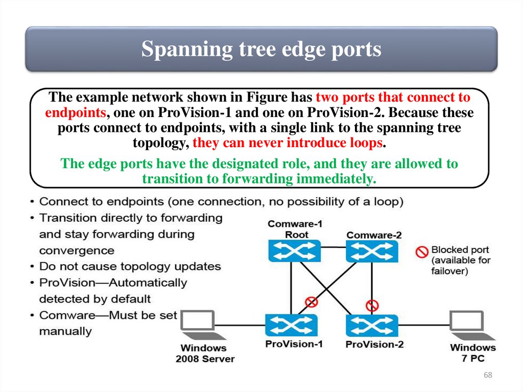
Spanning tree edge portsThe example network shown in Figure has two ports that connect to
endpoints, one on ProVision-1 and one on ProVision-2. Because these
ports connect to endpoints, with a single link to the spanning tree
topology, they can never introduce loops.
The edge ports have the designated role, and they are allowed to
transition to forwarding immediately.
68
69.
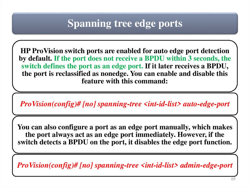
Spanning tree edge portsHP ProVision switch ports are enabled for auto edge port detection
by default. If the port does not receive a BPDU within 3 seconds, the
switch defines the port as an edge port. If it later receives a BPDU,
the port is reclassified as nonedge. You can enable and disable this
feature with this command:
ProVision(config)# [no] spanning-tree <int-id-list> auto-edge-port
You can also configure a port as an edge port manually, which makes
the port always act as an edge port immediately. However, if the
switch detects a BPDU on the port, it disables the edge port function.
ProVision(config)# [no] spanning-tree <int-id-list> admin-edge-port
69
70.
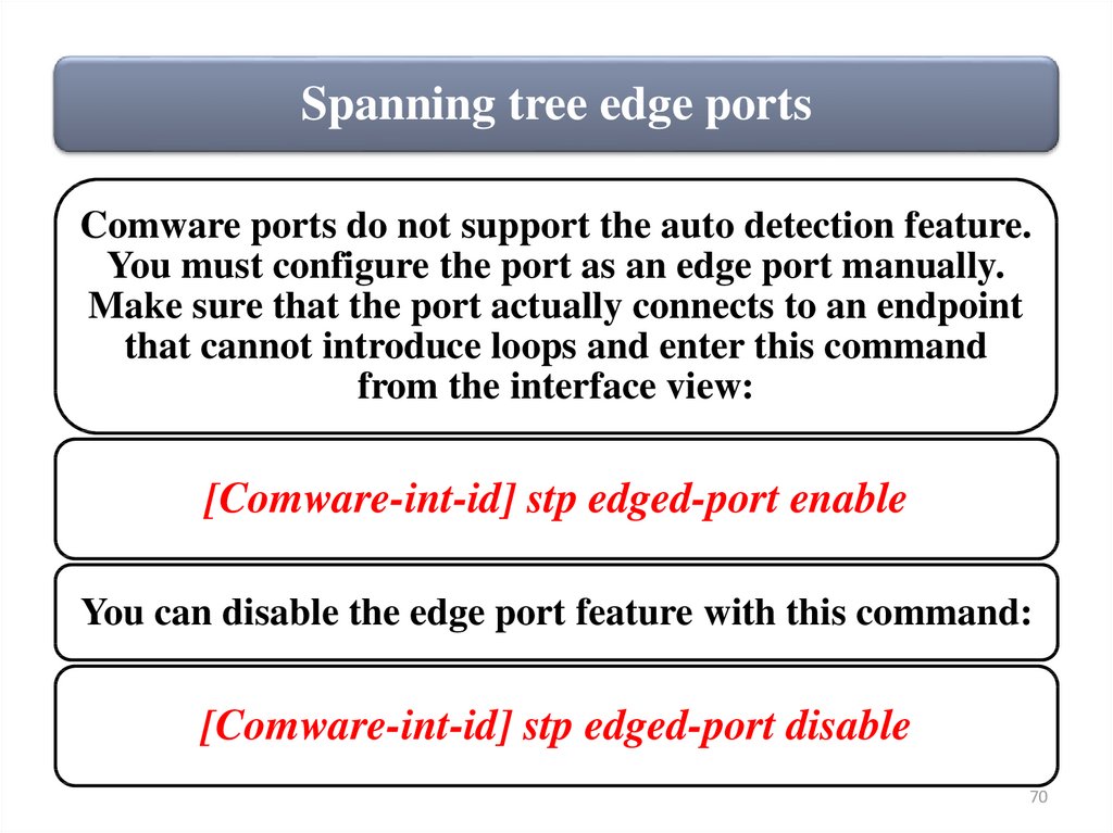
Spanning tree edge portsComware ports do not support the auto detection feature.
You must configure the port as an edge port manually.
Make sure that the port actually connects to an endpoint
that cannot introduce loops and enter this command
from the interface view:
[Comware-int-id] stp edged-port enable
You can disable the edge port feature with this command:
[Comware-int-id] stp edged-port disable
70
71.
Issues with RSTPThe spanning tree always sets up shortest paths to the root, which
might not be the best path for specific traffic. You set Comware-1 as
the root because it is the default gateway, so most traffic is directed
to it. However, what if you wanted to set up Comware-2 as the
default gateway for some VLANs? Traffic would still need to pass
through Comware-1 because Comware-1 is the root.
71
72.
Spanning Tree2. Multiple Spanning Tree
Protocol (MSTP)
72
73.
MSTP solutionMSTP, IEEE standard 802.1s, provided an extension to STP
and RSTP in order to deal with the issues outlined in this
chapter. Later 802.1s was merged into 802.1Q-2005, so
MSTP is now part of the Ethernet standard.
MSTP allows switches to set up multiple spanning trees,
called spanning tree instances. Each spanning tree instance
is associated with a different group of VLANs. Different
spanning tree instances can have different root bridges,
leading to different topologies that use different links.
Traffic for some VLANs can use some links while traffic
for other VLANs use other links, which significantly
improves network resource utilization while maintaining a
loop-free environment in each VLAN broadcast domain.
73
74.
MSTP solutionFigure shows two MSTP instances. In addition, each network also
requires the default instance 0, which has some special roles.
74
75.
MSTP solutionAs you see in Figure, this plan creates two spanning tree topologies,
one used by instance 1 (and 0) and one used by instance 2. The first
topology uses the uplinks between the ProVision switches and
Comware-1, and the second topology uses the uplinks between the
ProVision switches and Comware-2.
75
76.
MSTP regionBefore configuring MSTP, you should understand how to set up a region, as illustrated in
Figure .
The MSTP region lets MSTP switches guarantee that
they are using the same VLAN-to-instance mappings.
It consists of these settings:
• Region name
• Revision number
• Instance-to-VLAN mapping
All of the settings must match for switches to become part of the same MSTP region.
76
77.
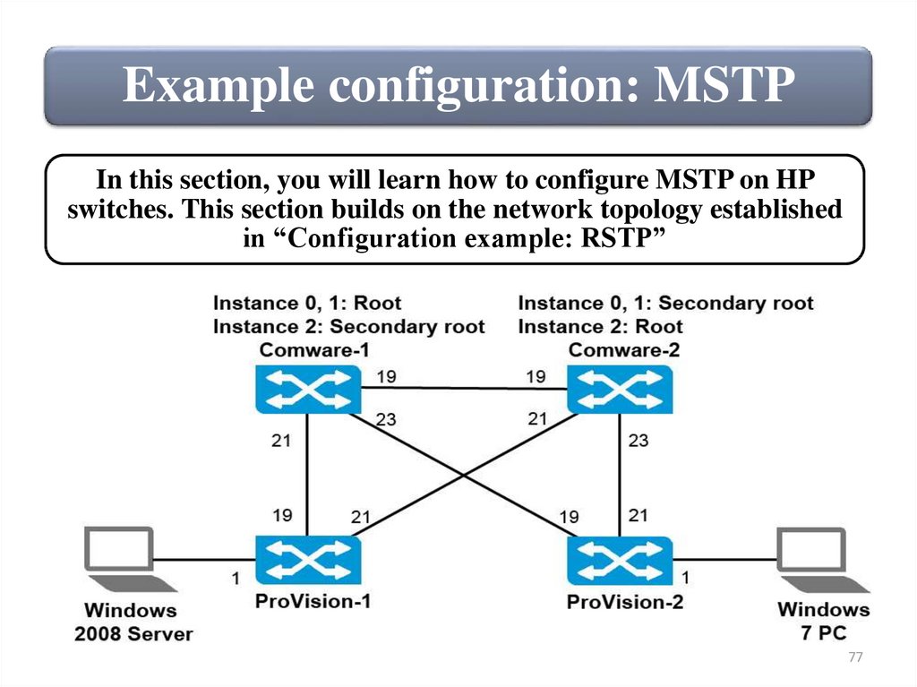
Example configuration: MSTPIn this section, you will learn how to configure MSTP on HP
switches. This section builds on the network topology established
in “Configuration example: RSTP”
77
78.
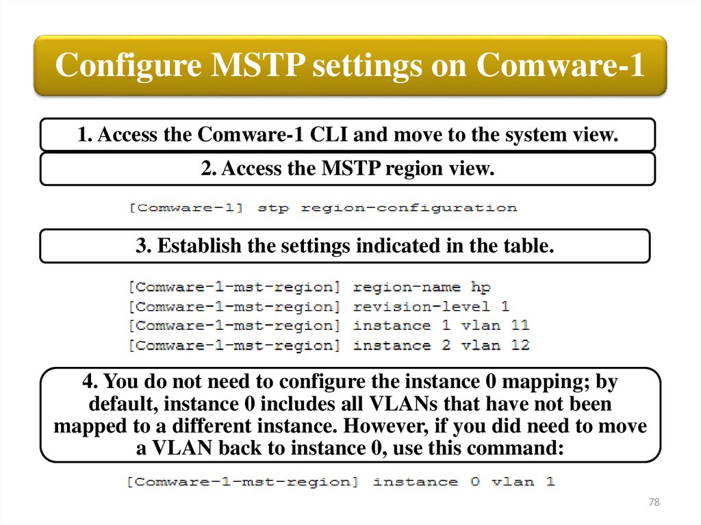
Configure MSTP settings on Comware-11. Access the Comware-1 CLI and move to the system view.
2. Access the MSTP region view.
3. Establish the settings indicated in the table.
4. You do not need to configure the instance 0 mapping; by
default, instance 0 includes all VLANs that have not been
mapped to a different instance. However, if you did need to move
a VLAN back to instance 0, use this command:
78
79.
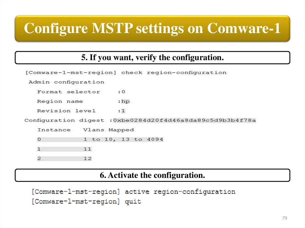
Configure MSTP settings on Comware-15. If you want, verify the configuration.
6. Activate the configuration.
79
80.
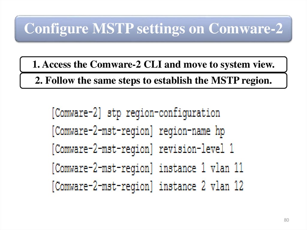
Configure MSTP settings on Comware-21. Access the Comware-2 CLI and move to system view.
2. Follow the same steps to establish the MSTP region.
80
81.
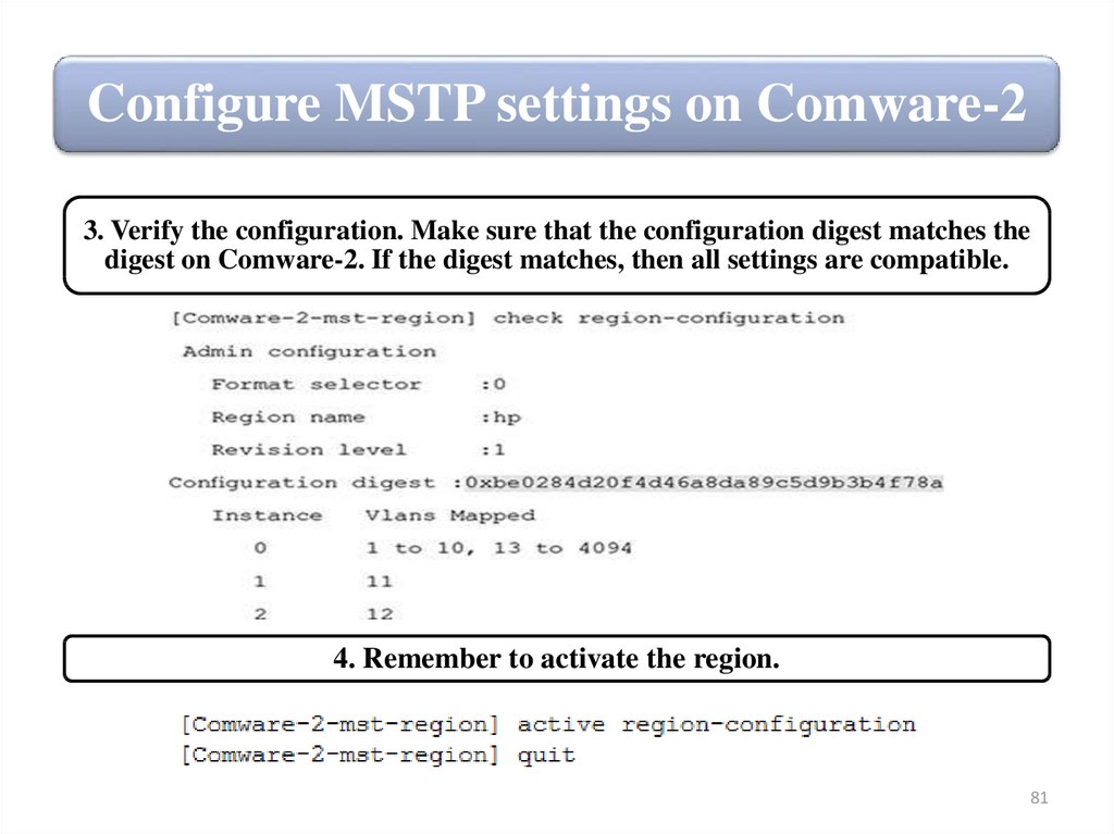
Configure MSTP settings on Comware-23. Verify the configuration. Make sure that the configuration digest matches the
digest on Comware-2. If the digest matches, then all settings are compatible.
4. Remember to activate the region.
81
82.
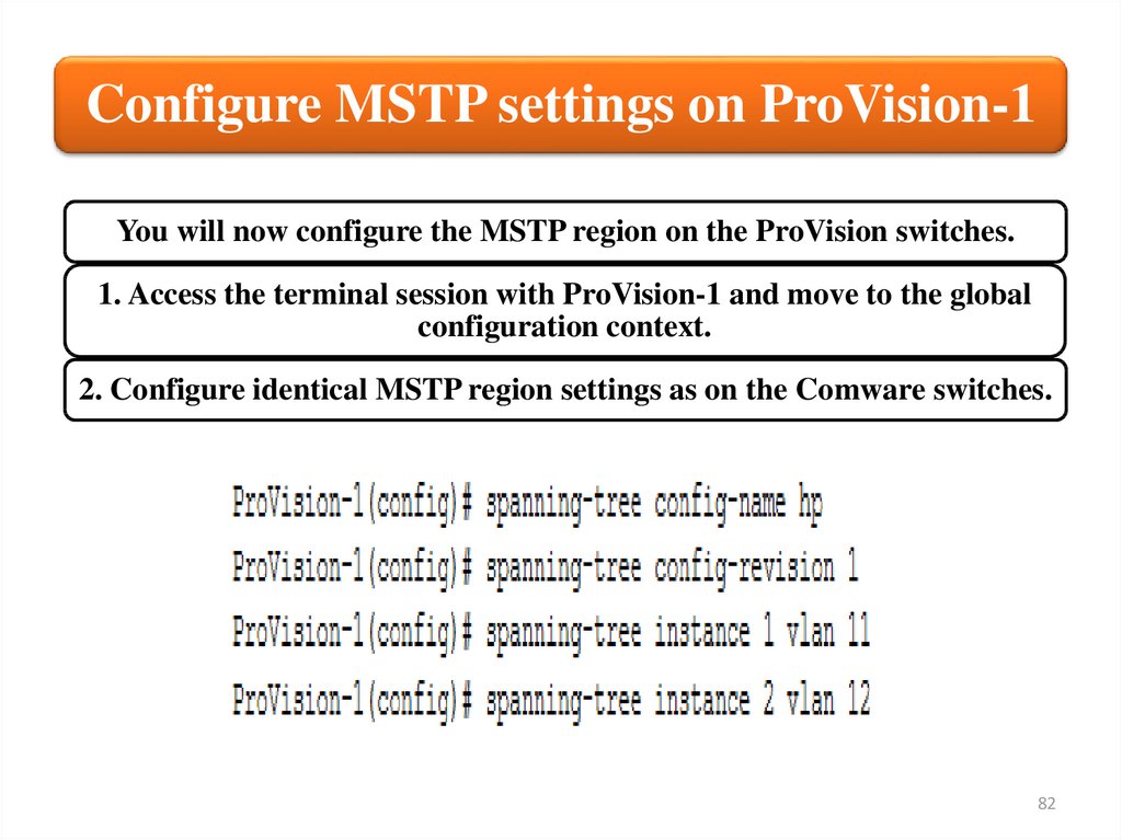
Configure MSTP settings on ProVision-1You will now configure the MSTP region on the ProVision switches.
1. Access the terminal session with ProVision-1 and move to the global
configuration context.
2. Configure identical MSTP region settings as on the Comware switches.
82
83.
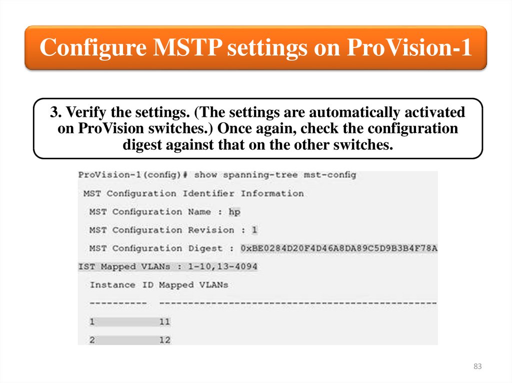
Configure MSTP settings on ProVision-13. Verify the settings. (The settings are automatically activated
on ProVision switches.) Once again, check the configuration
digest against that on the other switches.
83
84.
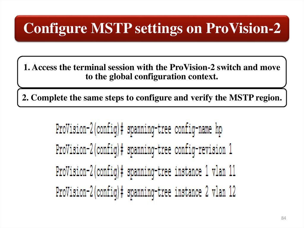
Configure MSTP settings on ProVision-21. Access the terminal session with the ProVision-2 switch and move
to the global configuration context.
2. Complete the same steps to configure and verify the MSTP region.
84
85.
Configure MSTP settings on ProVision-23. Verify the settings. (The settings are automatically activated
on ProVision switches.) Once again, check the configuration
digest against that on the other switches.
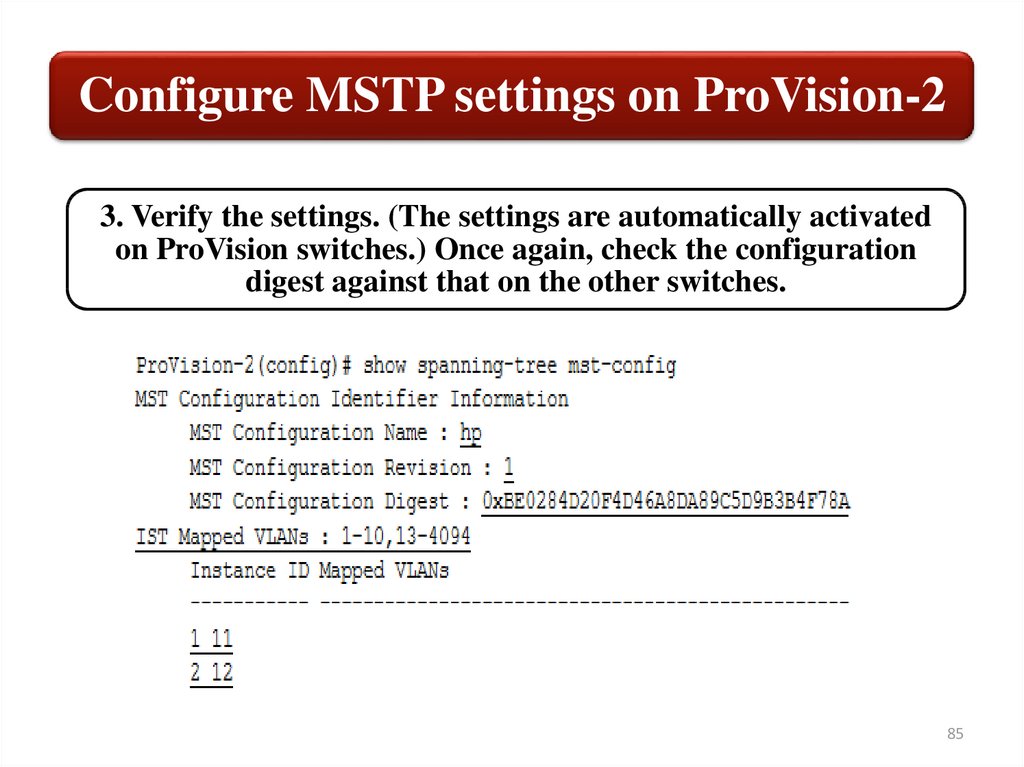
85
86.
Configure the instance root settings andset standard costs for Comware switches
Now that the switches are in the same MSTP region, they will
elect a root for each instance. It is best practice to select
different roots for different instances so as to load-balance
traffic. Table shows the settings for this example configuration.
You will also learn how to configure the Comware switches to
use 802.1t for their path cost standard. Setting a standard is best
practice for RSTP and MSTP.
86
87.
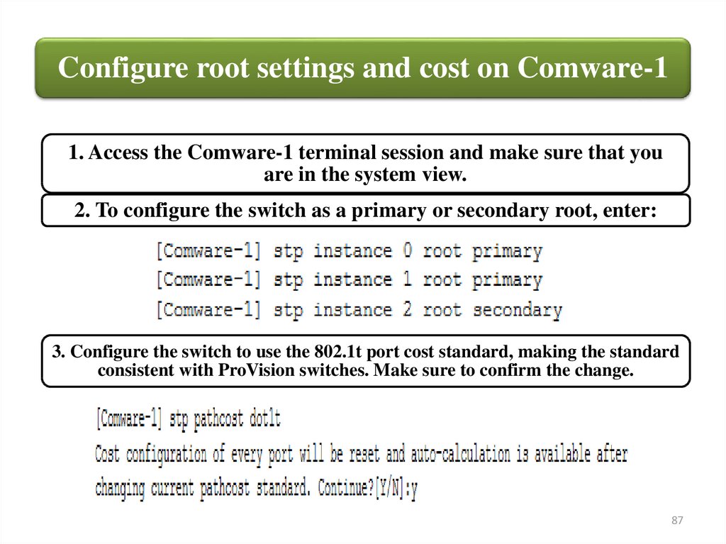
Configure root settings and cost on Comware-11. Access the Comware-1 terminal session and make sure that you
are in the system view.
2. To configure the switch as a primary or secondary root, enter:
3. Configure the switch to use the 802.1t port cost standard, making the standard
consistent with ProVision switches. Make sure to confirm the change.
87
88.
Configure root settings and cost on Comware-24. Access the Comware-2 switch terminal session.
5. Use similar commands to configure this switch as the secondary
and primary root of the correct instances.
6. Configure the switch to use the 802.1t port cost standard.
88
89.
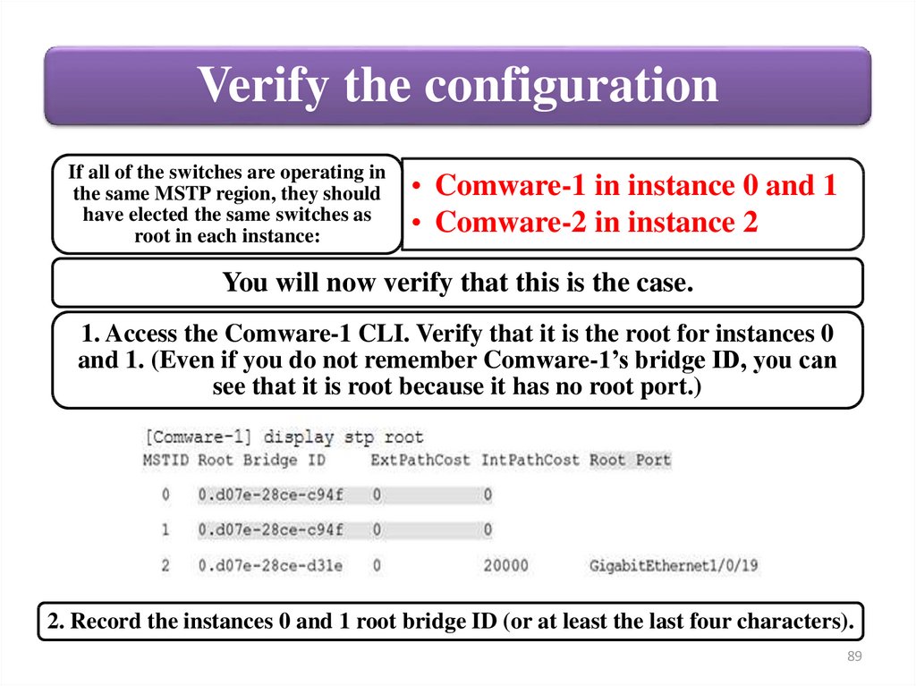
Verify the configurationIf all of the switches are operating in
the same MSTP region, they should
have elected the same switches as
root in each instance:
• Comware-1 in instance 0 and 1
• Comware-2 in instance 2
You will now verify that this is the case.
1. Access the Comware-1 CLI. Verify that it is the root for instances 0
and 1. (Even if you do not remember Comware-1’s bridge ID, you can
see that it is root because it has no root port.)
2. Record the instances 0 and 1 root bridge ID (or at least the last four characters).
89
90.
Verify the configuration3. Access the terminal session for Comware-2. Verify that it is
the root for instance 2.
4. Record the instance 2 root bridge ID (or at least the last four characters).
90
91.
Verify the configuration7. Access the ProVision-1 CLI and verify that the switch’s root
for each instance matches the root on the Comware switches.
You must enter the show spanning-tree root-history command
for each instance separately.
91
92.
9293.
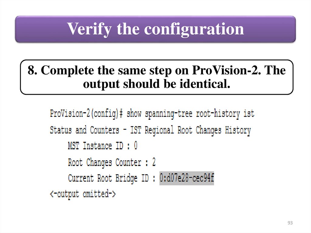
Verify the configuration8. Complete the same step on ProVision-2. The
output should be identical.
93
94.
9495.
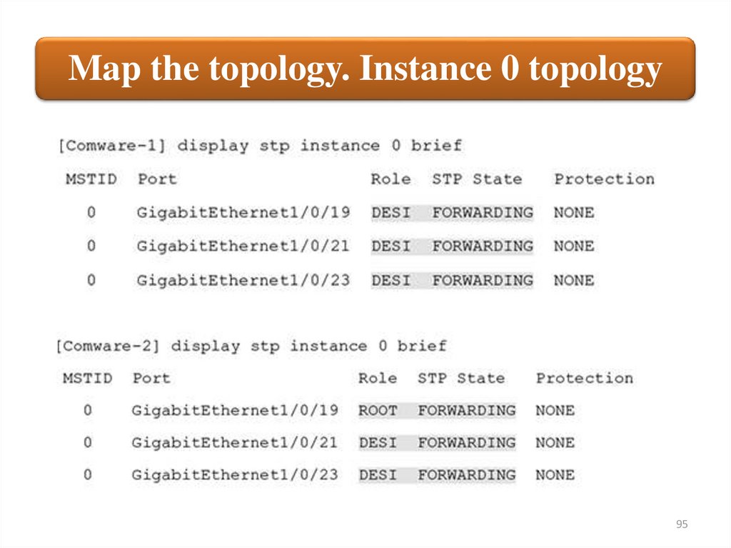
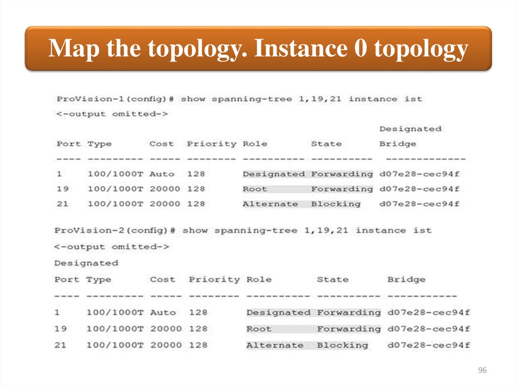
Map the topology. Instance 0 topology95
96.
Map the topology. Instance 0 topology96
97.
Map the topology. Instance 0 topology97
98.
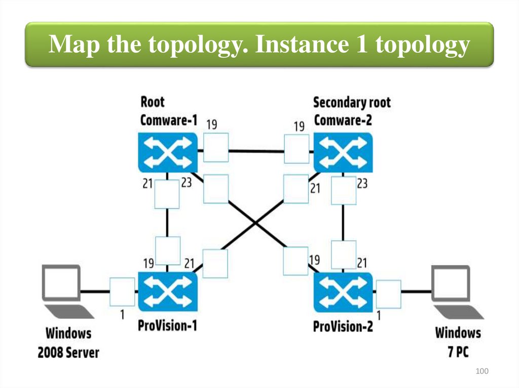
Map the topology. Instance 1 topology98
99.
Map the topology. Instance 1 topology99
100.
Map the topology. Instance 1 topology100
101.
Map the topology. Instance 2 topology101
102.
Map the topology. Instance 2 topology102
103.
Map the topology. Instance 2 topology103
104.
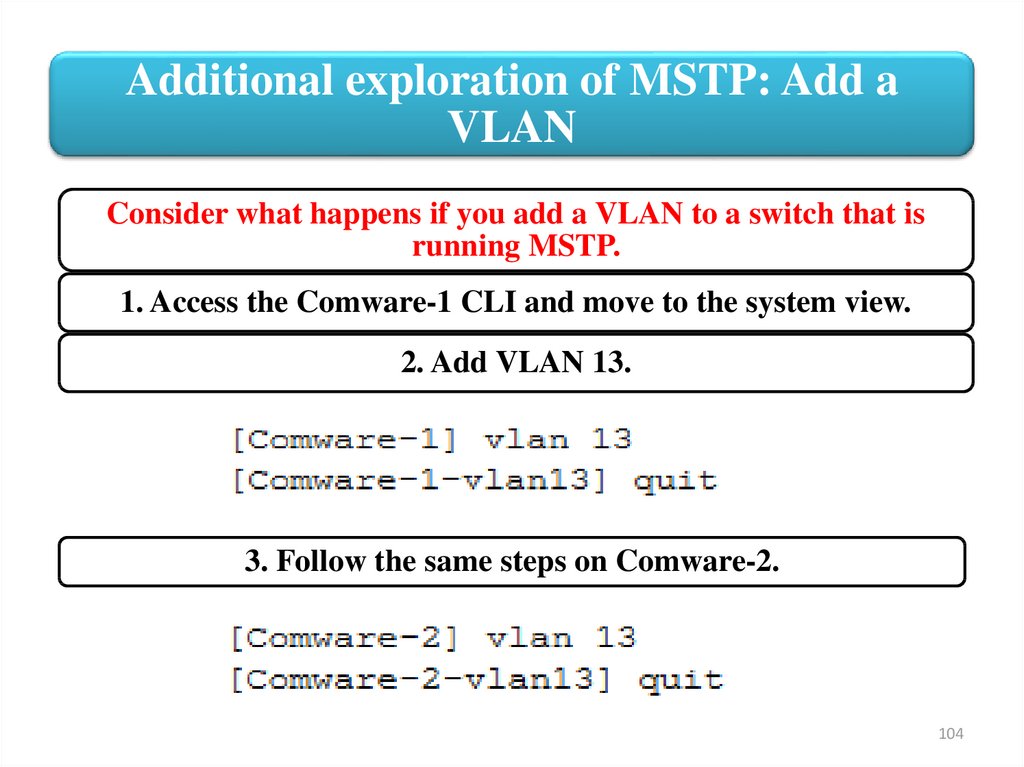
Additional exploration of MSTP: Add aVLAN
Consider what happens if you add a VLAN to a switch that is
running MSTP.
1. Access the Comware-1 CLI and move to the system view.
2. Add VLAN 13.
3. Follow the same steps on Comware-2.
104
105.
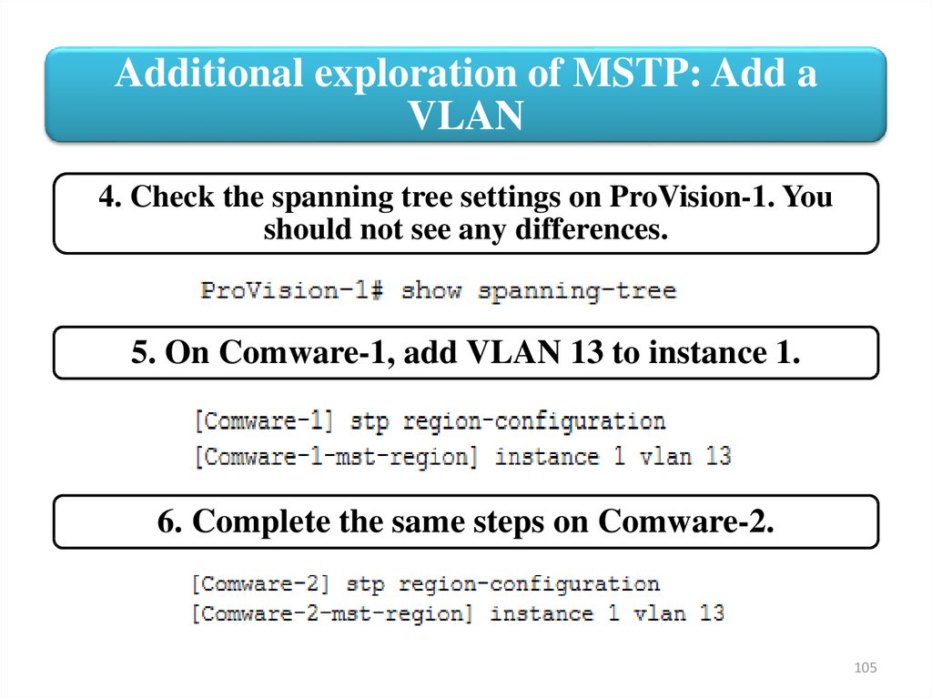
Additional exploration of MSTP: Add aVLAN
4. Check the spanning tree settings on ProVision-1. You
should not see any differences.
5. On Comware-1, add VLAN 13 to instance 1.
6. Complete the same steps on Comware-2.
105
106.
Additional exploration of MSTP: Add aVLAN
7. Activate the MSTP region configuration on both
Comware-1 and Comware-2.
The switches will exchange a number of reconvergence
log messages as soon as the configuration is activated.
Although you have not made any changes to the
ProVision switches, you will see that this configuration
has actually affected them.
106
107.
Additional exploration of MSTP: Add aVLAN
8. On ProVision-1, check the switch-to-switch interfaces’
port roles for each MSTP instance.
107
108.
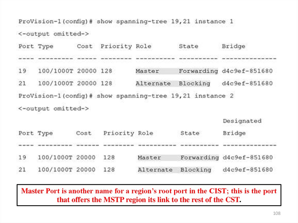
Master Port is another name for a region’s root port in the CIST; this is the portthat offers the MSTP region its link to the rest of the CST.
108
109.
Additional exploration of MSTP: Add aVLAN
9. As you see, ProVision-1 now is forwarding only on the link to
Comware-1 no matter what the instance or VLAN.
10. Compare the MSTP region settings on Comware-1,
Comware-2, and ProVision-1 for a clue as to what has happened.
109
110.
110111.
Additional exploration of MSTP: Add aVLAN
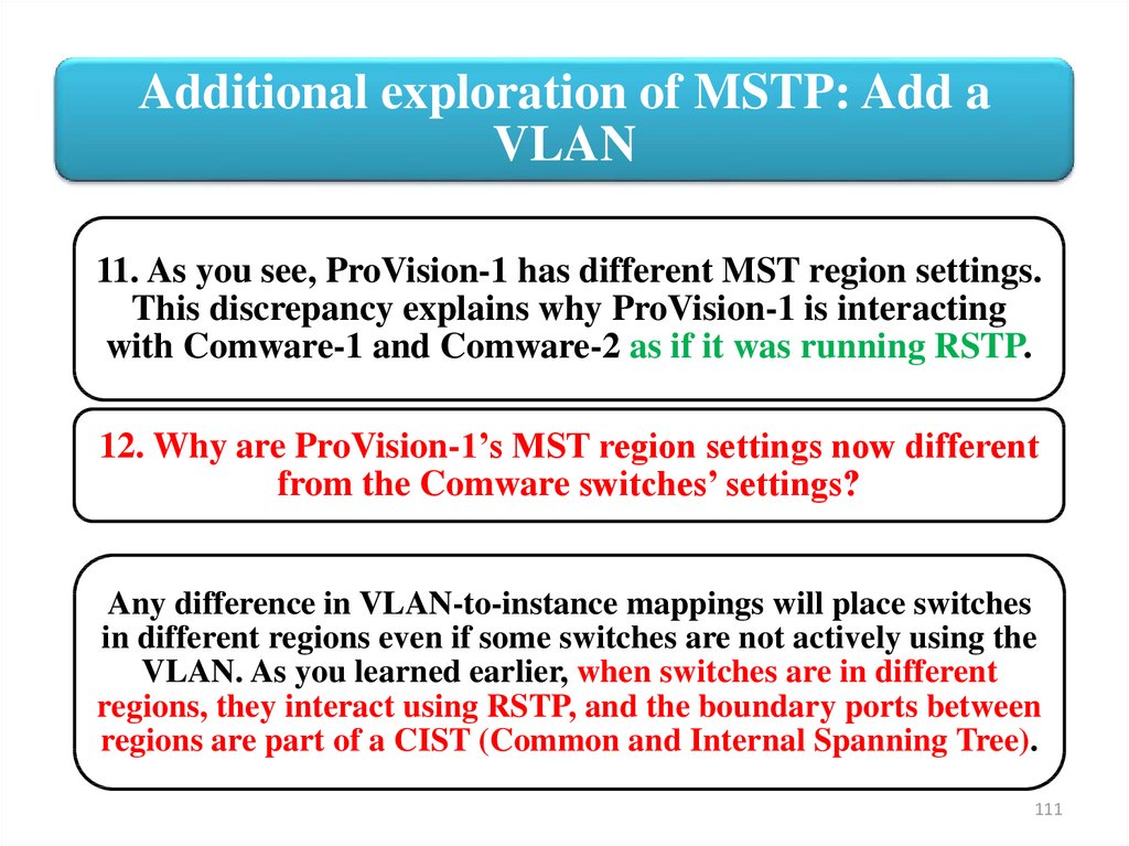
11. As you see, ProVision-1 has different MST region settings.
This discrepancy explains why ProVision-1 is interacting
with Comware-1 and Comware-2 as if it was running RSTP.
12. Why are ProVision-1’s MST region settings now different
from the Comware switches’ settings?
Any difference in VLAN-to-instance mappings will place switches
in different regions even if some switches are not actively using the
VLAN. As you learned earlier, when switches are in different
regions, they interact using RSTP, and the boundary ports between
regions are part of a CIST (Common and Internal Spanning Tree).
111
112.
Additional exploration of MSTP: Add aVLAN
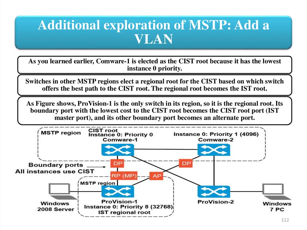
As you learned earlier, Comware-1 is elected as the CIST root because it has the lowest
instance 0 priority.
Switches in other MSTP regions elect a regional root for the CIST based on which switch
offers the best path to the CIST root. The regional root becomes the IST root.
As Figure shows, ProVision-1 is the only switch in its region, so it is the regional root. Its
boundary port with the lowest cost to the CIST root becomes the CIST root port (IST
master port), and its other boundary port becomes an alternate port.
112
113.
Additional exploration of MSTP: Add aVLAN
In short, no load-balancing occurs on the
MSTP boundary ports. Therefore, adding a
VLAN and moving that VLAN from instance 0
to another instance in an active network can
cause disruptions and nonoptimal link
utilization.
Note! Plan in advance and place all VLANs
that might be used in the future in the desired
instance on all switches.
113