


 internet
Similar presentations:


")

Lecture 2. Hardware Fundamentals
1.
Lecture 2Hardware
Fundamentals
1
2.
Objectives1. Identify the purpose and use of
network hardware.
2. Identify switch management
interfaces.
3. Command line interface (CLI).
4. Menu interface.
2
3.
HardwareFundamentals
1. Identify the purpose and use of
common network hardware
3
4.
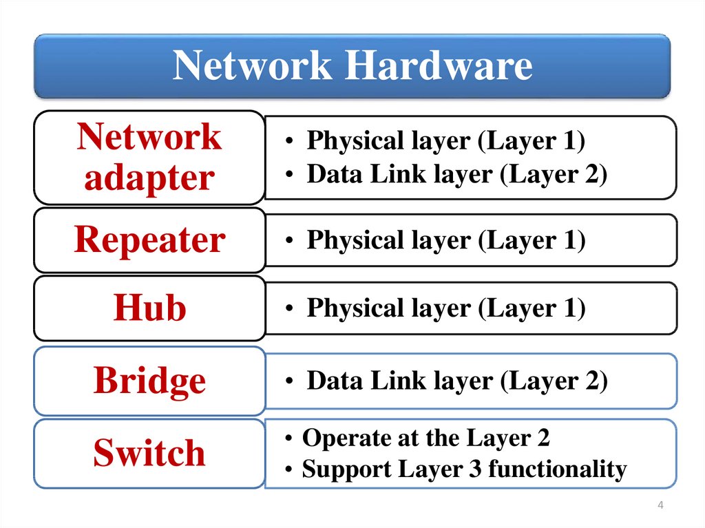
Network HardwareNetwork
adapter
• Physical layer (Layer 1)
• Data Link layer (Layer 2)
Repeater
• Physical layer (Layer 1)
Hub
• Physical layer (Layer 1)
Bridge
• Data Link layer (Layer 2)
Switch
• Operate at the Layer 2
• Support Layer 3 functionality
4
5.
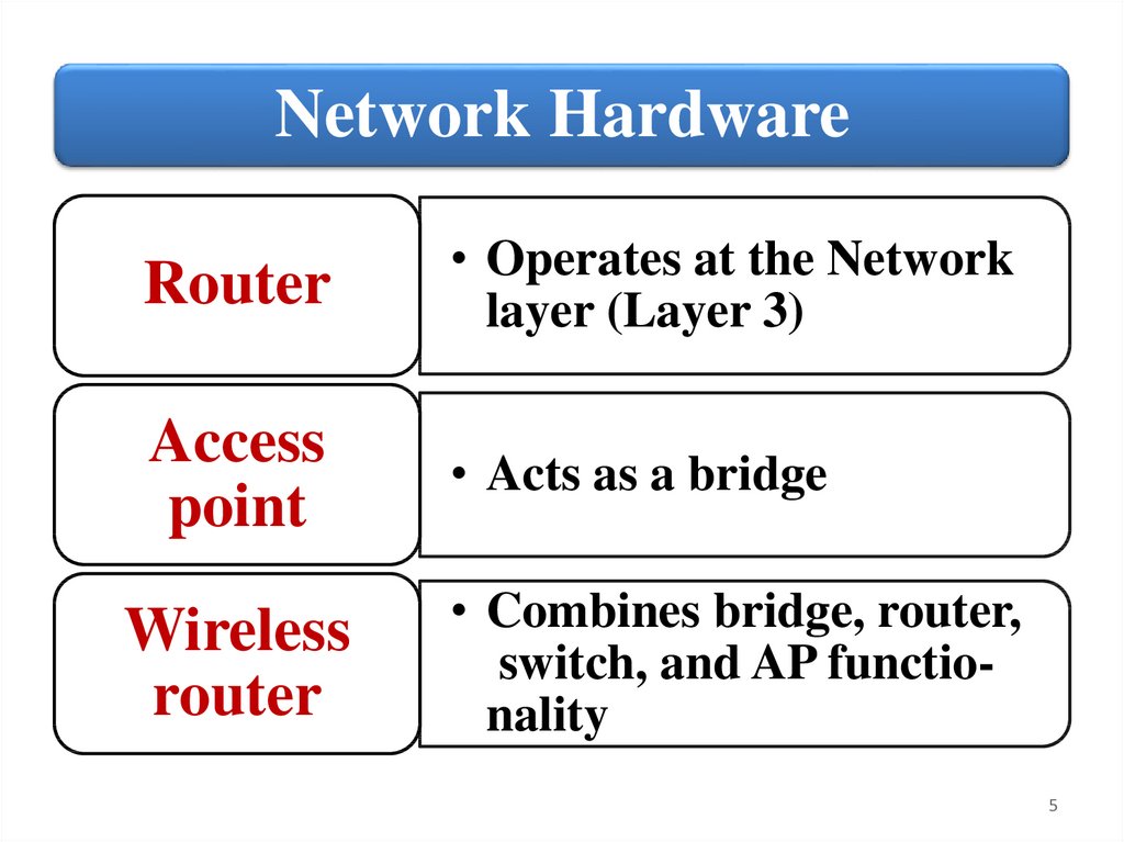
Network HardwareRouter
• Operates at the Network
layer (Layer 3)
Access
point
• Acts as a bridge
Wireless
router
• Combines bridge, router,
switch, and AP functionality
5
6.
Network AdapterA network adapter (called a network interface
controller or NIC) is a hardware card installed in a
computer so it can communicate on a network. The
network adapter transmits and receives data onto
the network cable.
The NIC is both a Physical layer and Data link
layer device, as it provides physical access to a
networking medium and provides a low-level
addressing system through the use of MAC
addresses that are uniquely assigned to network
interfaces.
6
7.
Types of Network AdapterThere are
two basic
types of
networks:
wired and
wireless:
• Wired Network
Adapter
• Wireless Network
Adapter
• Network USB
Adapter
7
8.
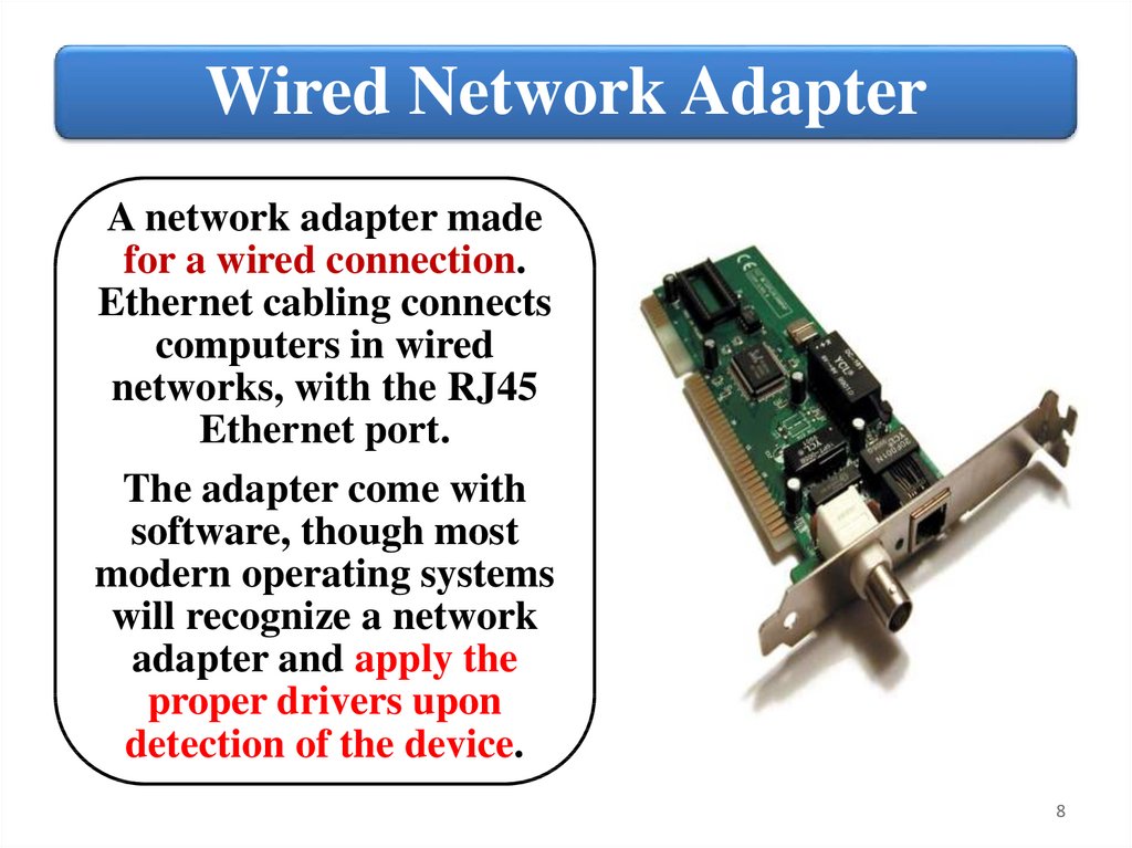
Wired Network AdapterA network adapter made
for a wired connection.
Ethernet cabling connects
computers in wired
networks, with the RJ45
Ethernet port.
The adapter come with
software, though most
modern operating systems
will recognize a network
adapter and apply the
proper drivers upon
detection of the device.
8
9.
Wireless Network AdapterA wireless network interface controller (WNIC) is a
network interface controller which connects to a
radio-based computer network. Both desktop and
laptop PCs usually come configured with wireless
adapters.
9
10.
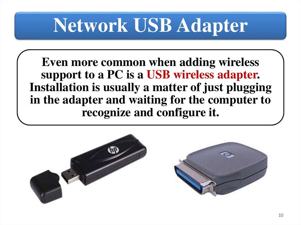
Network USB AdapterEven more common when adding wireless
support to a PC is a USB wireless adapter.
Installation is usually a matter of just plugging
in the adapter and waiting for the computer to
recognize and configure it.
10
11.
Adapter MAC addressWhether it is built‐in or added on, a
network adapter performs the same
functions for a PC or other network device.
The network adapter will be coded with a
unique Media Access Control (MAC)
address used to identify the device on the
network and will have a means of
connecting to the network transmission
media.
11
12.
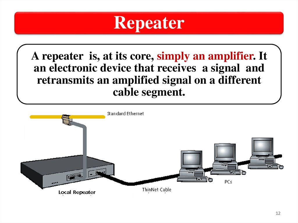
RepeaterA repeater is, at its core, simply an amplifier. It
an electronic device that receives a signal and
retransmits an amplified signal on a different
cable segment.
12
13.
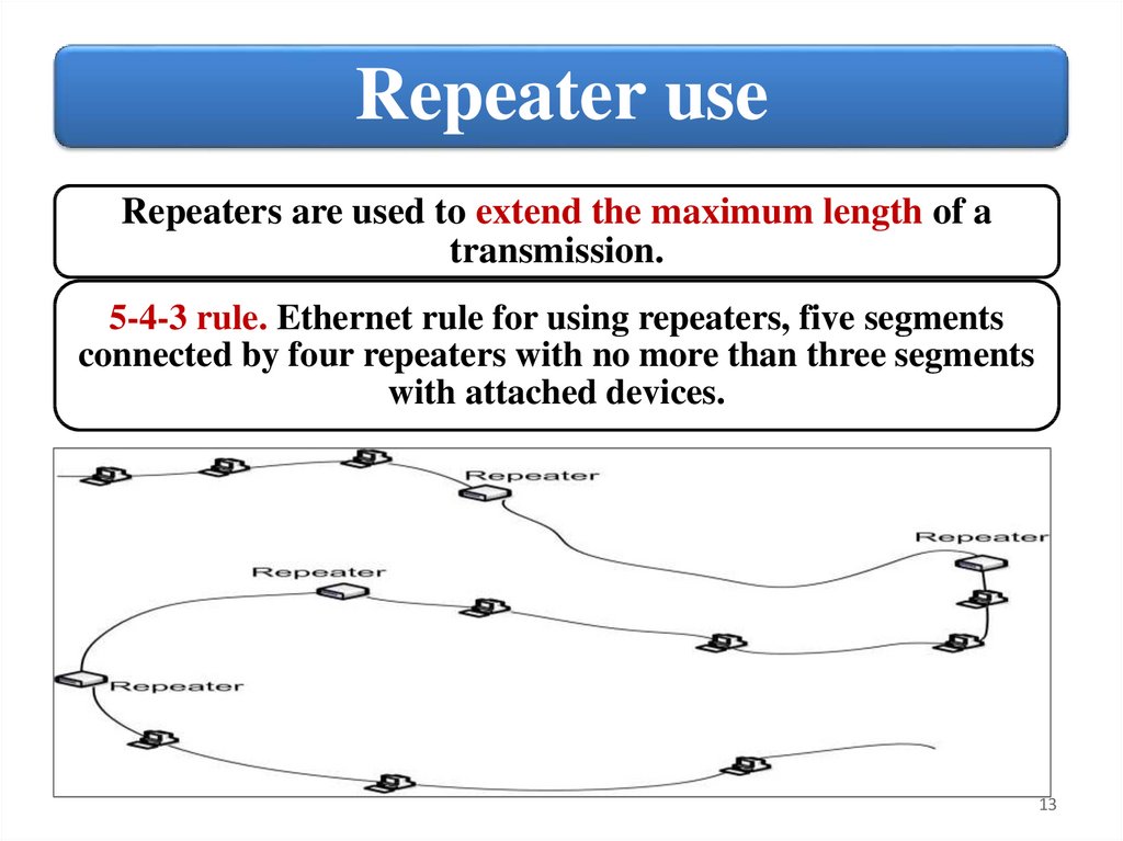
Repeater useRepeaters are used to extend the maximum length of a
transmission.
5-4-3 rule. Ethernet rule for using repeaters, five segments
connected by four repeaters with no more than three segments
with attached devices.
13
14.
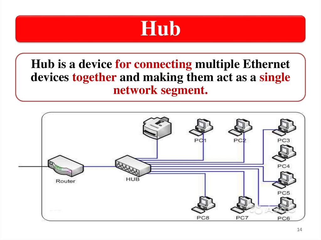
HubHub is a device for connecting multiple Ethernet
devices together and making them act as a single
network segment.
14
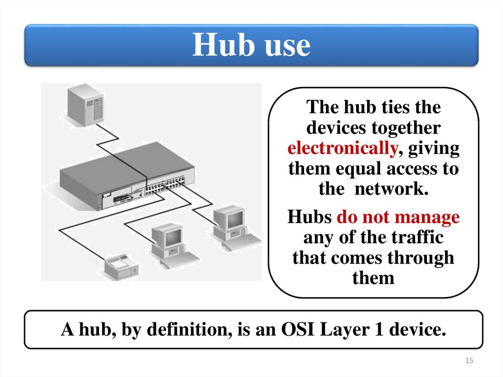
15.
Hub useThe hub ties the
devices together
electronically, giving
them equal access to
the network.
Hubs do not manage
any of the traffic
that comes through
them
A hub, by definition, is an OSI Layer 1 device.
15
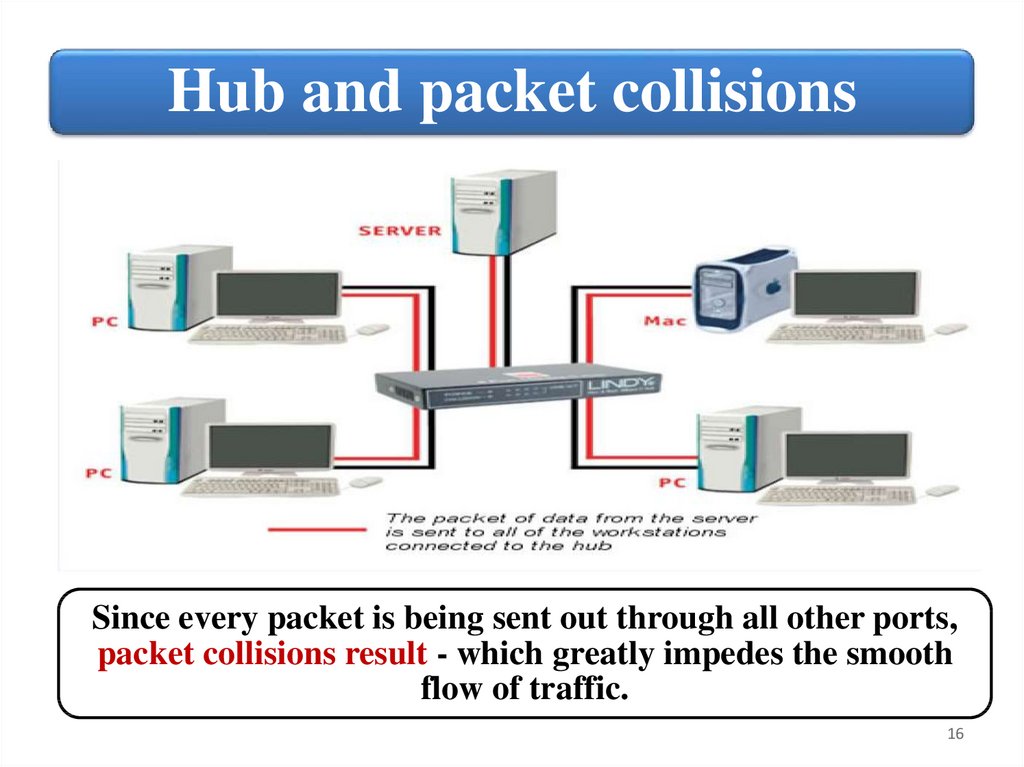
16.
Hub and packet collisionsSince every packet is being sent out through all other ports,
packet collisions result - which greatly impedes the smooth
flow of traffic.
16
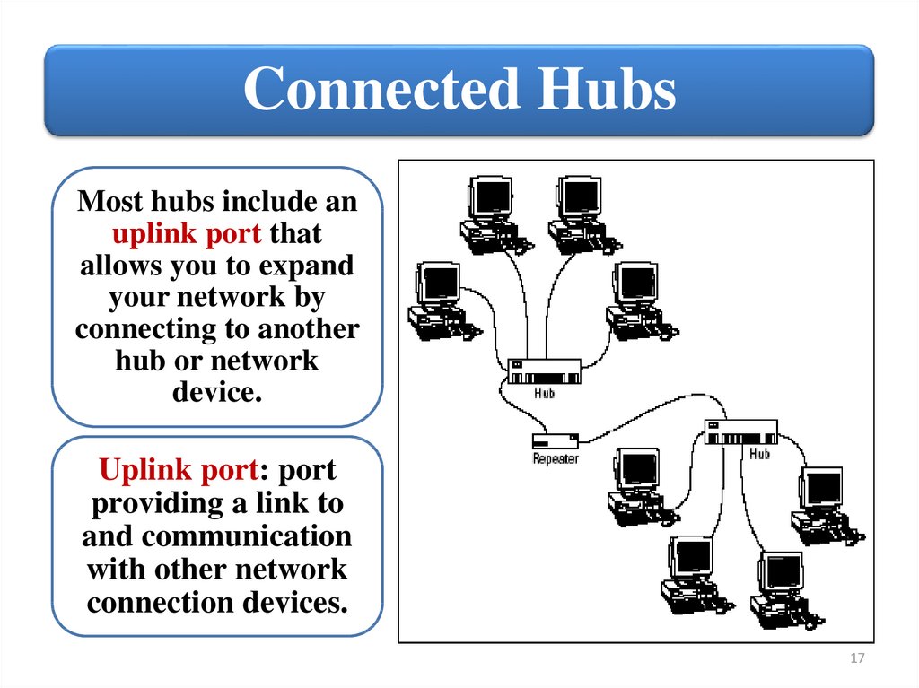
17.
Connected HubsMost hubs include an
uplink port that
allows you to expand
your network by
connecting to another
hub or network
device.
Uplink port: port
providing a link to
and communication
with other network
connection devices.
17
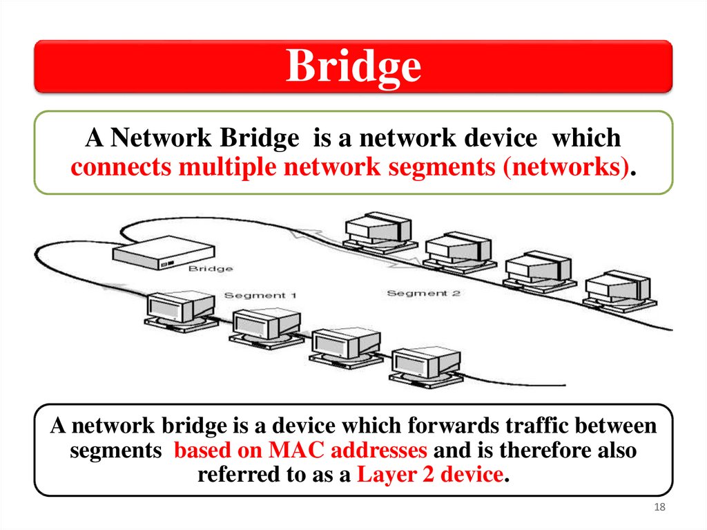
18.
BridgeA Network Bridge is a network device which
connects multiple network segments (networks).
A network bridge is a device which forwards traffic between
segments based on MAC addresses and is therefore also
referred to as a Layer 2 device.
18
19.
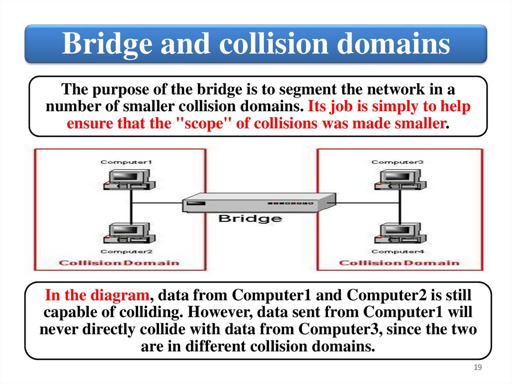
Bridge and collision domainsThe purpose of the bridge is to segment the network in a
number of smaller collision domains. Its job is simply to help
ensure that the "scope" of collisions was made smaller.
In the diagram, data from Computer1 and Computer2 is still
capable of colliding. However, data sent from Computer1 will
never directly collide with data from Computer3, since the two
are in different collision domains.
19
20.
Bridge and media typesA Network Bridge is a hardware, that
connects two or more networks – maybe one
a wired one and the other a wireless one – so
that they can communicate with each other.
The network bridge can create connections
between different media types of network.
Network Bridge automates the configuration
that is required in order to forward
information from one type of media to
another.
20
21.
Bridge SampleThe device in Figure is a bridge by the traditional definition
because it allows you to connect 10Base2, 10Base5 (through the
AUI port), and 10Base‐T network segments.
21
22.
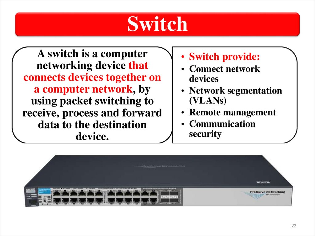
SwitchA switch is a computer
networking device that
connects devices together on
a computer network, by
using packet switching to
receive, process and forward
data to the destination
device.
• Switch provide:
• Connect network
devices
• Network segmentation
(VLANs)
• Remote management
• Communication
security
22
23.
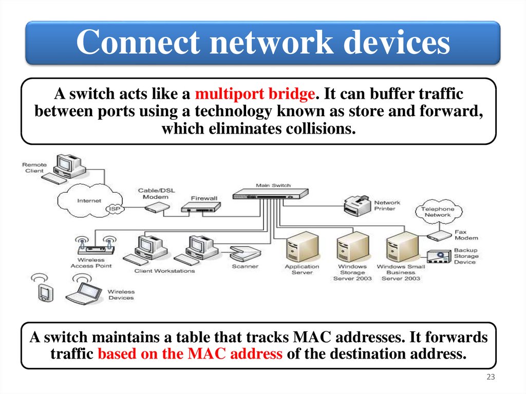
Connect network devicesA switch acts like a multiport bridge. It can buffer traffic
between ports using a technology known as store and forward,
which eliminates collisions.
A switch maintains a table that tracks MAC addresses. It forwards
traffic based on the MAC address of the destination address.
23
24.
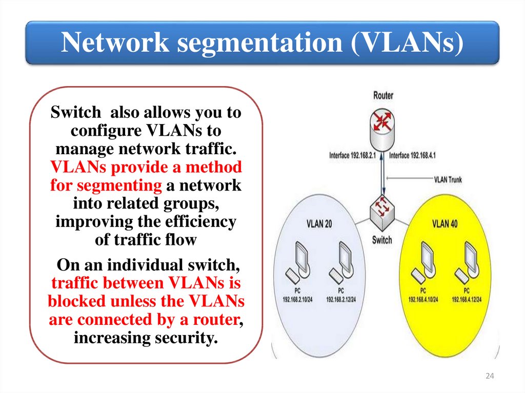
Network segmentation (VLANs)Switch also allows you to
configure VLANs to
manage network traffic.
VLANs provide a method
for segmenting a network
into related groups,
improving the efficiency
of traffic flow
On an individual switch,
traffic between VLANs is
blocked unless the VLANs
are connected by a router,
increasing security.
24
25.
Switch and remote managementMost switches are designed to support remote
management. This means that you can
remotely manage configurable parameters
and also update switch software, back up
configuration information, manage port
activity, and so forth.
Many switches also provide a high level of
communication security by encrypting
communication with connected devices.
25
26.
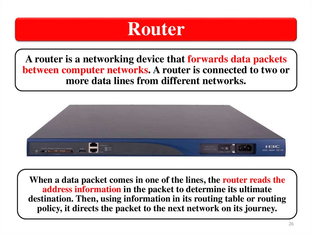
RouterA router is a networking device that forwards data packets
between computer networks. A router is connected to two or
more data lines from different networks.
When a data packet comes in one of the lines, the router reads the
address information in the packet to determine its ultimate
destination. Then, using information in its routing table or routing
policy, it directs the packet to the next network on its journey.
26
27.
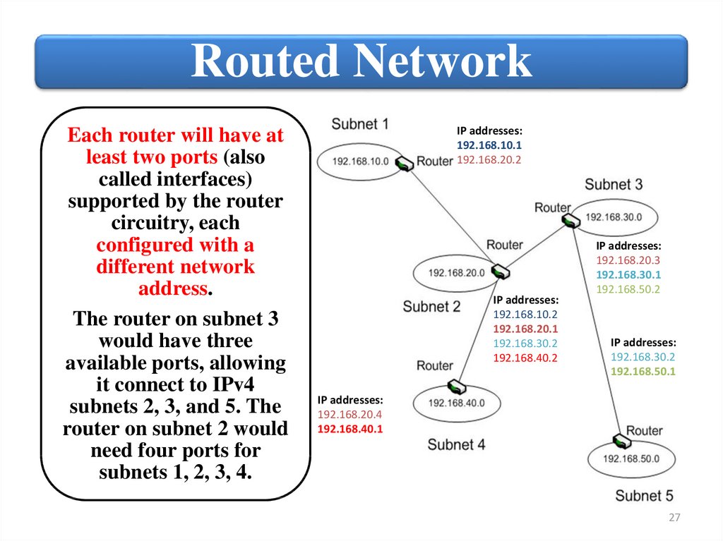
Routed NetworkEach router will have at
least two ports (also
called interfaces)
supported by the router
circuitry, each
configured with a
different network
address.
The router on subnet 3
would have three
available ports, allowing
it connect to IPv4
subnets 2, 3, and 5. The
router on subnet 2 would
need four ports for
subnets 1, 2, 3, 4.
IP addresses:
192.168.10.1
192.168.20.2
IP addresses:
192.168.10.2
192.168.20.1
192.168.30.2
192.168.40.2
IP addresses:
192.168.20.3
192.168.30.1
192.168.50.2
IP addresses:
192.168.30.2
192.168.50.1
IP addresses:
192.168.20.4
192.168.40.1
27
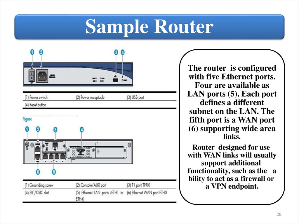
28.
Sample RouterThe router is configured
with five Ethernet ports.
Four are available as
LAN ports (5). Each port
defines a different
subnet on the LAN. The
fifth port is a WAN port
(6) supporting wide area
links.
Router designed for use
with WAN links will usually
support additional
functionality, such as the a
bility to act as a firewall or
a VPN endpoint.
28
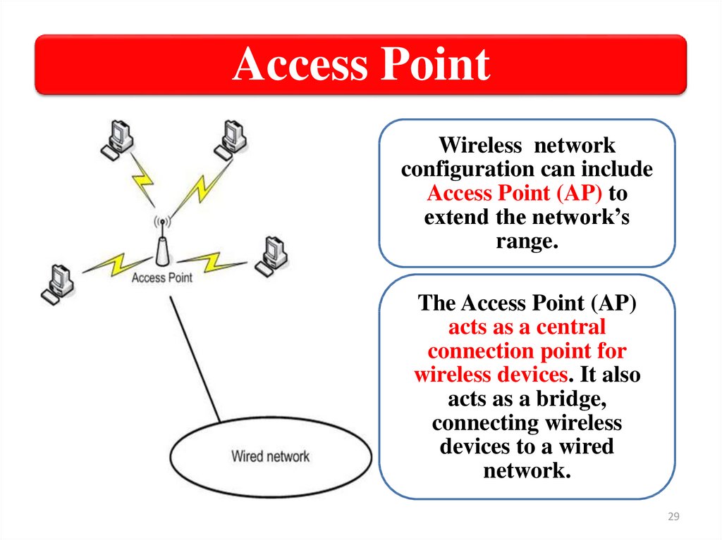
29.
Access PointWireless network
configuration can include
Access Point (AP) to
extend the network’s
range.
The Access Point (AP)
acts as a central
connection point for
wireless devices. It also
acts as a bridge,
connecting wireless
devices to a wired
network.
29
30.
MSM460 Front ViewThe Access Point
will have one or
more internal
radios. Each radio
can be configured
separately, and
usually you can
disable a radio if it
is not needed.
Most HP APs support both a web‐based
management tool and a CLI through which you can
configure the AP, including its radios.
30
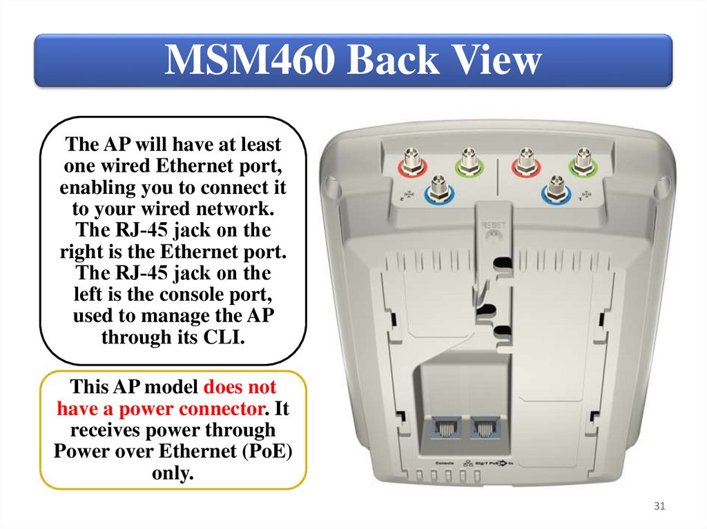
31.
MSM460 Back ViewThe AP will have at least
one wired Ethernet port,
enabling you to connect it
to your wired network.
The RJ‐45 jack on the
right is the Ethernet port.
The RJ‐45 jack on the
left is the console port,
used to manage the AP
through its CLI.
This AP model does not
have a power connector. It
receives power through
Power over Ethernet (PoE)
only.
31
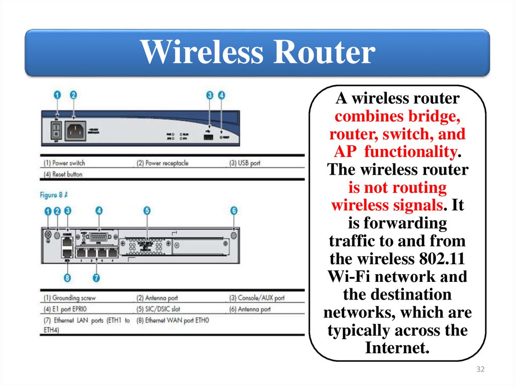
32.
Wireless RouterA wireless router
combines bridge,
router, switch, and
AP functionality.
The wireless router
is not routing
wireless signals. It
is forwarding
traffic to and from
the wireless 802.11
Wi‐Fi network and
the destination
networks, which are
typically across the
Internet.
32
33.
Wireless Router UseWireless routers is that they
give you an easy way to
share a high‐speed Internet
connection. In one common
configuration, a single
high‐speed modem
connection device, usually a
DSL or cable modem,
connects to the wireless
router’s uplink port and is
shared through the wired
client ports and with
wireless clients.
33
34.
SummaryThe
purpose
and use of
common
network
devices.
• Network adapter
• Repeater
• Hub
• Bridge
• Switch
• Router
• Access point
• Wireless router
34
35.
HardwareFundamentals
2. Identify switch management
interfaces.
35
36.
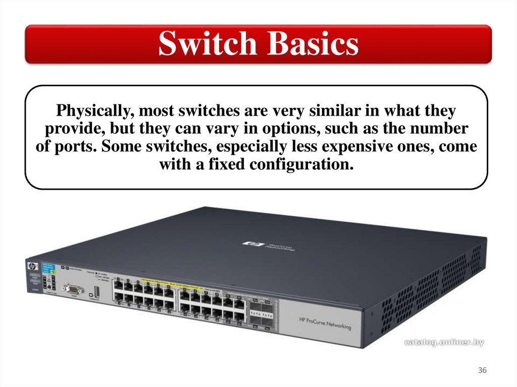
Switch BasicsPhysically, most switches are very similar in what they
provide, but they can vary in options, such as the number
of ports. Some switches, especially less expensive ones, come
with a fixed configuration.
36
37.
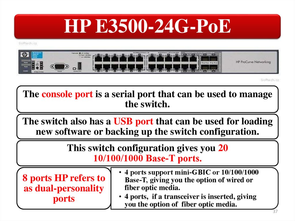
HP E3500-24G-PoEThe console port is a serial port that can be used to manage
the switch.
The switch also has a USB port that can be used for loading
new software or backing up the switch configuration.
This switch configuration gives you 20
10/100/1000 Base‐T ports.
8 ports HP refers to
as dual-personality
ports
• 4 ports support mini‐GBIC or 10/100/1000
Base‐T, giving you the option of wired or
fiber optic media.
• 4 ports, if a transceiver is inserted, giving
you the option of fiber optic media.
37
38.
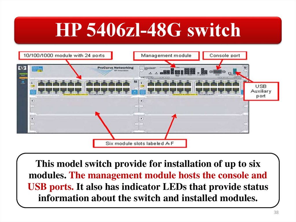
HP 5406zl‐48G switchThis model switch provide for installation of up to six
modules. The management module hosts the console and
USB ports. It also has indicator LEDs that provide status
information about the switch and installed modules.
38
39.
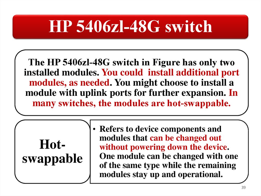
HP 5406zl‐48G switchThe HP 5406zl‐48G switch in Figure has only two
installed modules. You could install additional port
modules, as needed. You might choose to install a
module with uplink ports for further expansion. In
many switches, the modules are hot‐swappable.
Hotswappable
• Refers to device components and
modules that can be changed out
without powering down the device.
One module can be changed with one
of the same type while the remaining
modules stay up and operational.
39
40.
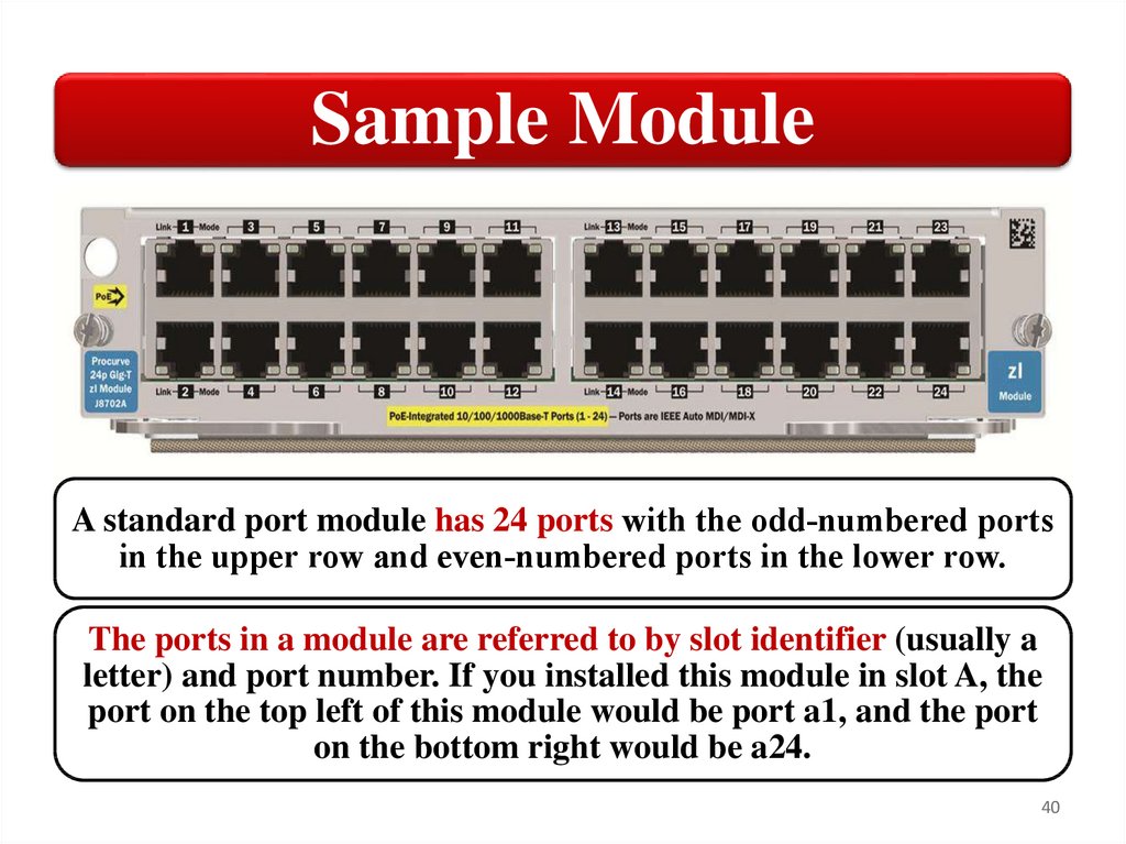
Sample ModuleA standard port module has 24 ports with the odd‐numbered ports
in the upper row and even‐numbered ports in the lower row.
The ports in a module are referred to by slot identifier (usually a
letter) and port number. If you installed this module in slot A, the
port on the top left of this module would be port a1, and the port
on the bottom right would be a24.
40
41.
Switch management optionsHP switches
have three
management
interface
options:
• Command line
interface (CLI)
(console port or over
the network);
• Menu interface
(console port or over
the network);
• Web interface (over
the network only).
41
42.
Switch management optionsThe Command line interface (CLI) is the most
powerful, but it is also the most difficult to use.
The menu interface is easier to use because you
select commands from a menu instead of typing
them. However, the menu interface limits the
management commands to which you have access.
The web interface is the least powerful, but it is the
easiest to use. The web interface gives you an easy
way to check the status of a switch from anywhere
on the network.
42
43.
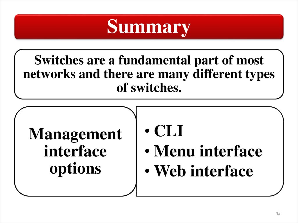
SummarySwitches are a fundamental part of most
networks and there are many different types
of switches.
Management
interface
options
• CLI
• Menu interface
• Web interface
43
44.
HardwareFundamentals
3. Command line interface (CLI)
44
45.
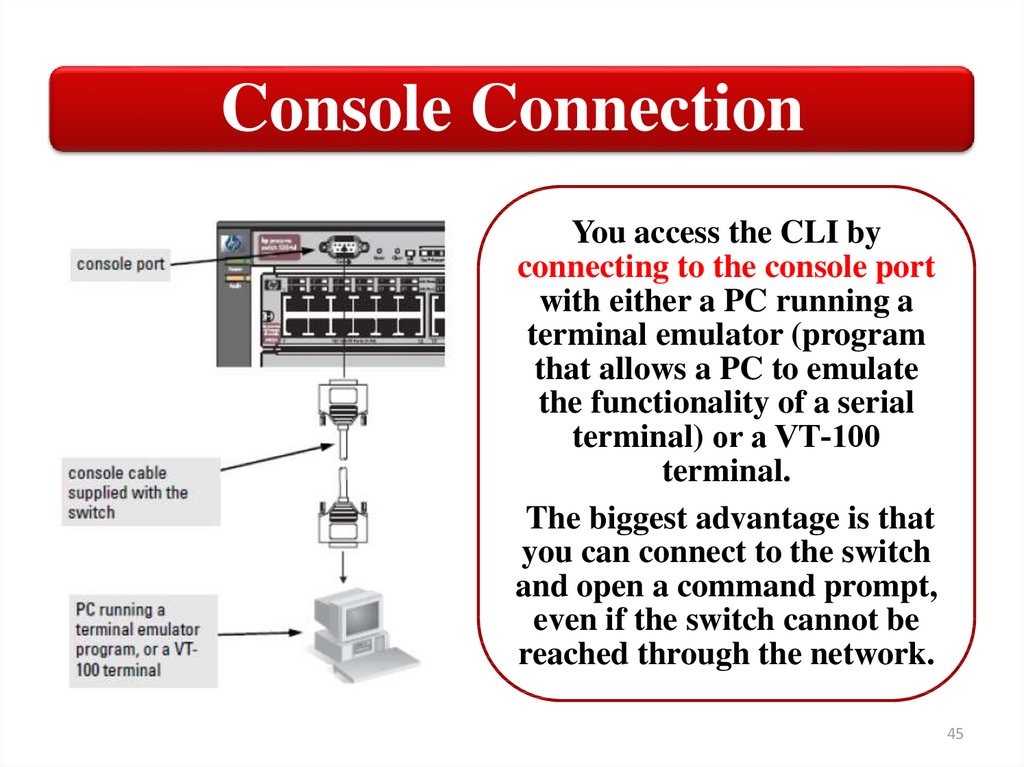
Console ConnectionYou access the CLI by
connecting to the console port
with either a PC running a
terminal emulator (program
that allows a PC to emulate
the functionality of a serial
terminal) or a VT‐100
terminal.
The biggest advantage is that
you can connect to the switch
and open a command prompt,
even if the switch cannot be
reached through the network.
45
46.
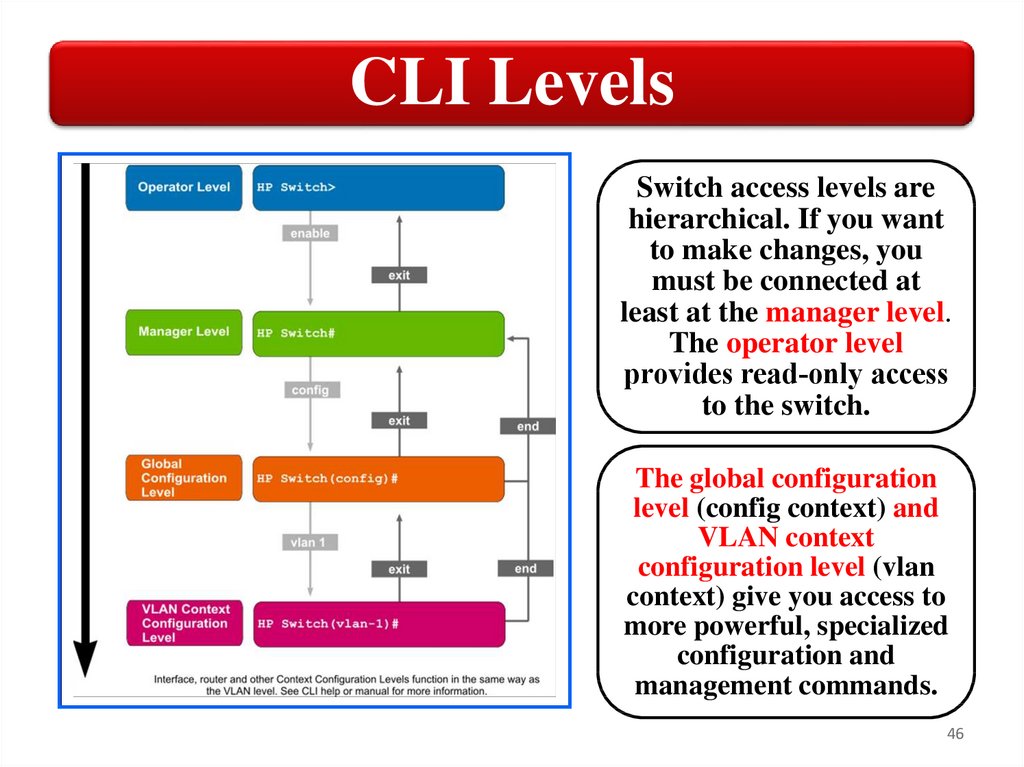
CLI LevelsSwitch access levels are
hierarchical. If you want
to make changes, you
must be connected at
least at the manager level.
The operator level
provides read‐only access
to the switch.
The global configuration
level (config context) and
VLAN context
configuration level (vlan
context) give you access to
more powerful, specialized
configuration and
management commands.
46
47.
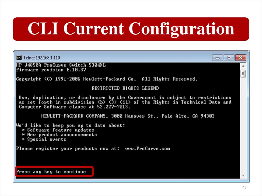
CLI Current Configuration47
48.
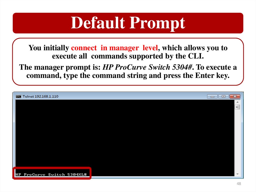
Default PromptYou initially connect in manager level, which allows you to
execute all commands supported by the CLI.
The manager prompt is: HP ProCurve Switch 5304#. To execute a
command, type the command string and press the Enter key.
48
49.
CLI Active ConfigurationTo view the configuration information currently being used by
your switch, run the following command: show running-config.
49
50.
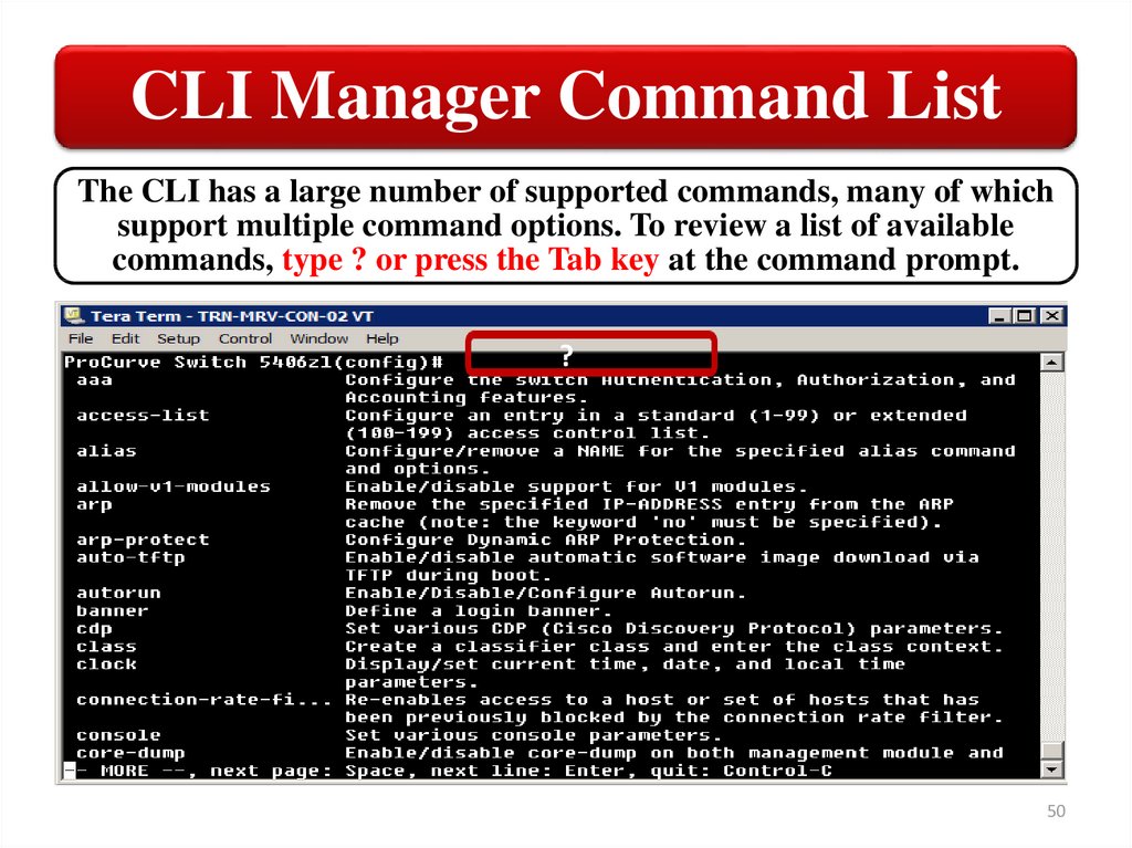
CLI Manager Command ListThe CLI has a large number of supported commands, many of which
support multiple command options. To review a list of available
commands, type ? or press the Tab key at the command prompt.
?
50
51.
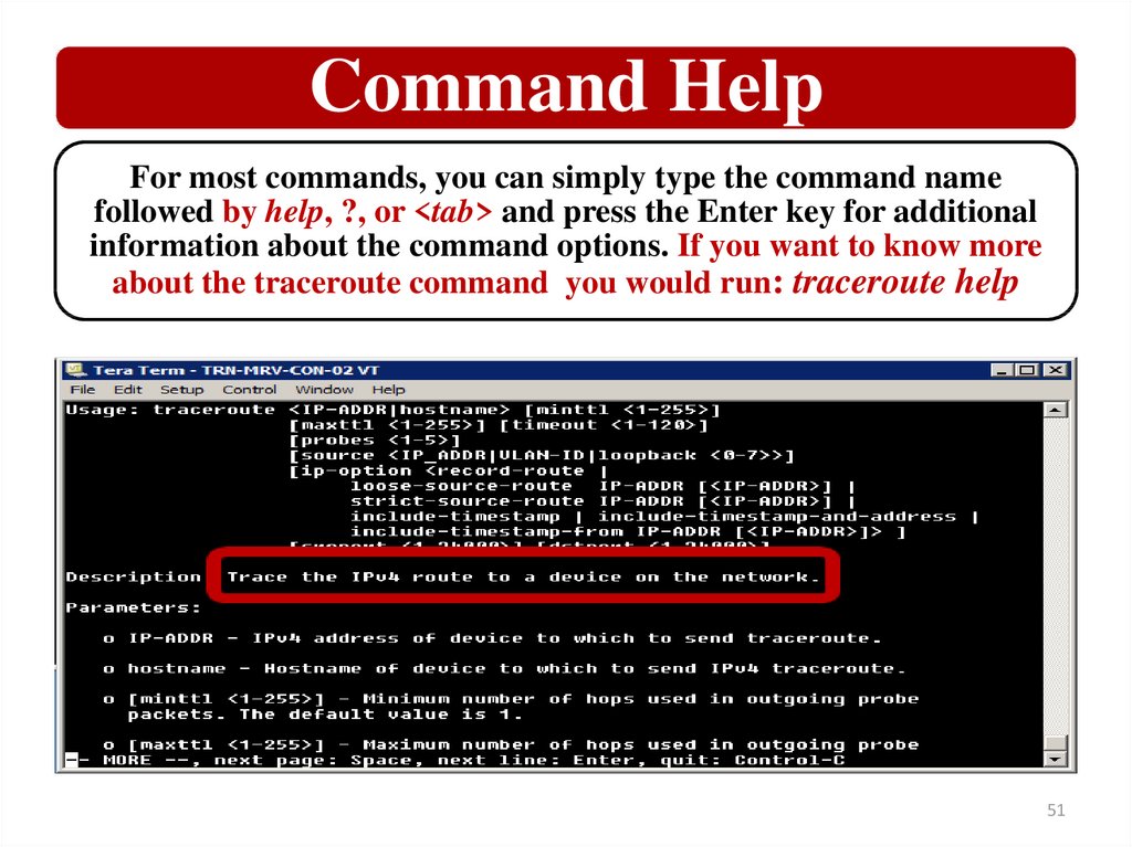
Command HelpFor most commands, you can simply type the command name
followed by help, ?, or <tab> and press the Enter key for additional
information about the command options. If you want to know more
about the traceroute command you would run: traceroute help
51
52.
Show CommandsSome commands support subcommands. One example of
this is the show command, which you saw earlier. For a list
of supported show commands, type show at the command
prompt, then type ? or press the Tab key.
52
53.
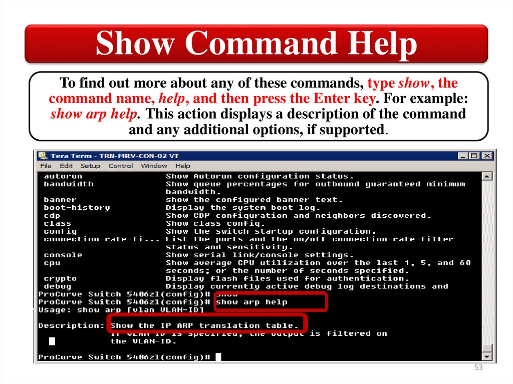
Show Command HelpTo find out more about any of these commands, type show, the
command name, help, and then press the Enter key. For example:
show arp help. This action displays a description of the command
and any additional options, if supported.
53
54.
Show command examplesThe show command also allows you to view
information about various configuration parameters.
To see a list of configured VLANs, for example, you
can run:
show vlans
To see routing information stored with the switch, run:
show ip route
54
55.
Show command examplesYou can get more information about
ports by running:
show interface
This will show a list of ports, packet
information for transmitted and received
packets, and a list of packet errors.
55
56.
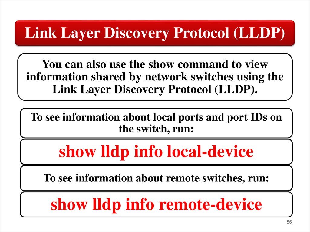
Link Layer Discovery Protocol (LLDP)You can also use the show command to view
information shared by network switches using the
Link Layer Discovery Protocol (LLDP).
To see information about local ports and port IDs on
the switch, run:
show lldp info local-device
To see information about remote switches, run:
show lldp info remote-device
56
57.
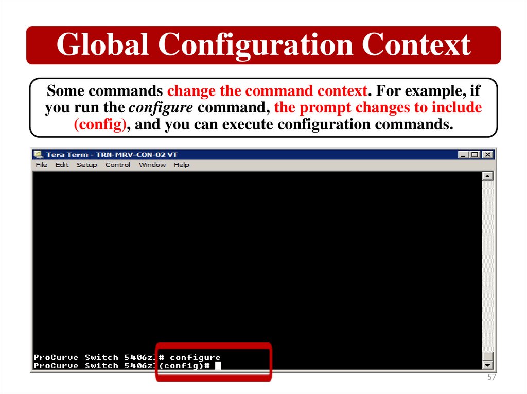
Global Configuration ContextSome commands change the command context. For example, if
you run the configure command, the prompt changes to include
(config), and you can execute configuration commands.
57
58.
Global Configuration CommandsNow, if you type ?, you receive a list of
configuration commands
58
59.
Switch setup using the CLIFrom here, you can enter basic setup information,
such as a contact person for the switch, the manager
password, DHCP/Bootp enable or disable, and IP
address information.
One action that you should take is to define a
descriptive and unique hostname for your switch,
which you must do in the configuration context. For
example, if you want to name the switch switch1, you
would run with Config context (global configuration
context):
hostname switch1
59
60.
Manager accessFor example, if you want to set the user name for manager
access as admin and set a password, you would run:
password manager user-name admin
To set the user name and password for operator access, you would
use password command. To set the operator user name as techie, run:
password operator user-name techie
To clear both passwords so that the switch is no longer
password protected, run:
no password all
60
61.
Global configuration context commandsConfig context (global configuration context)
gives you access to advanced configuration
commands. From there, you can enter the
configuration context for a particular port. If you
wanted to manage port 10, you would run:
interface 10
Your prompt would be similar to the following:
switch1(eth-10)#
61
62.
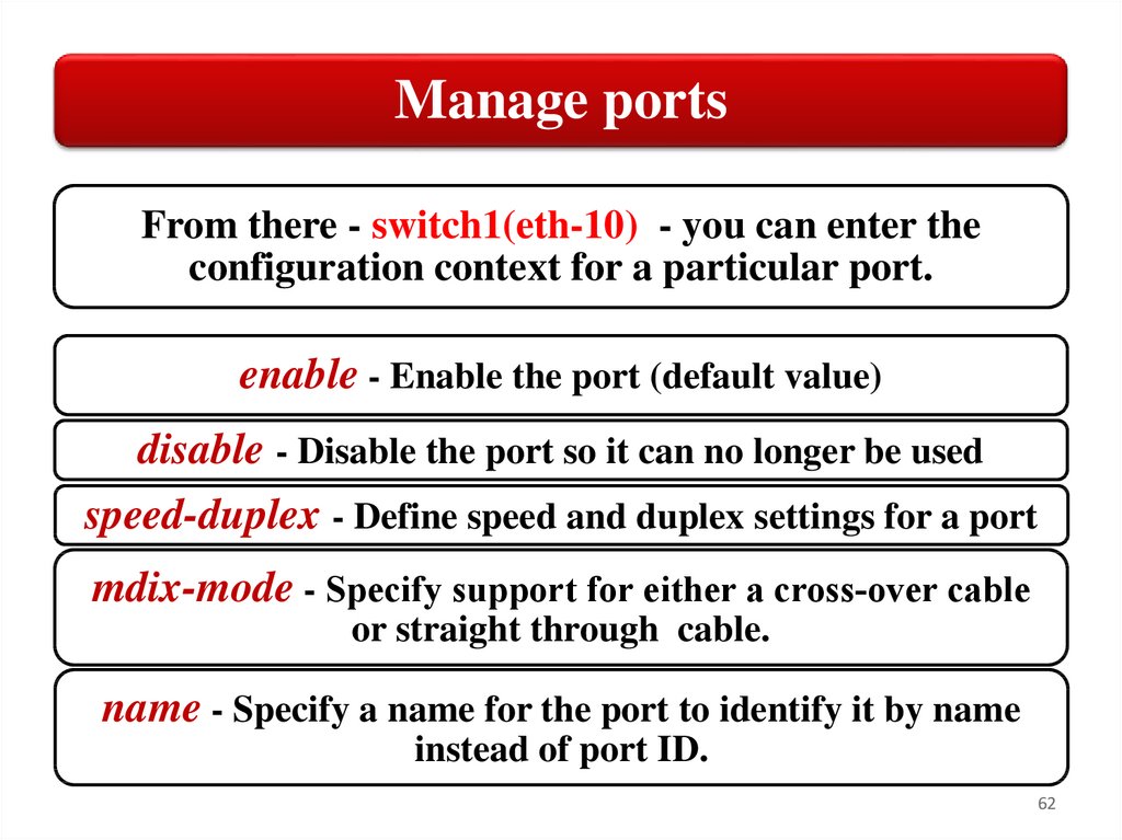
Manage portsFrom there - switch1(eth-10) - you can enter the
configuration context for a particular port.
enable - Enable the port (default value)
disable - Disable the port so it can no longer be used
speed-duplex - Define speed and duplex settings for a port
mdix-mode - Specify support for either a cross‐over cable
or straight through cable.
name - Specify a name for the port to identify it by name
instead of port ID.
62
63.
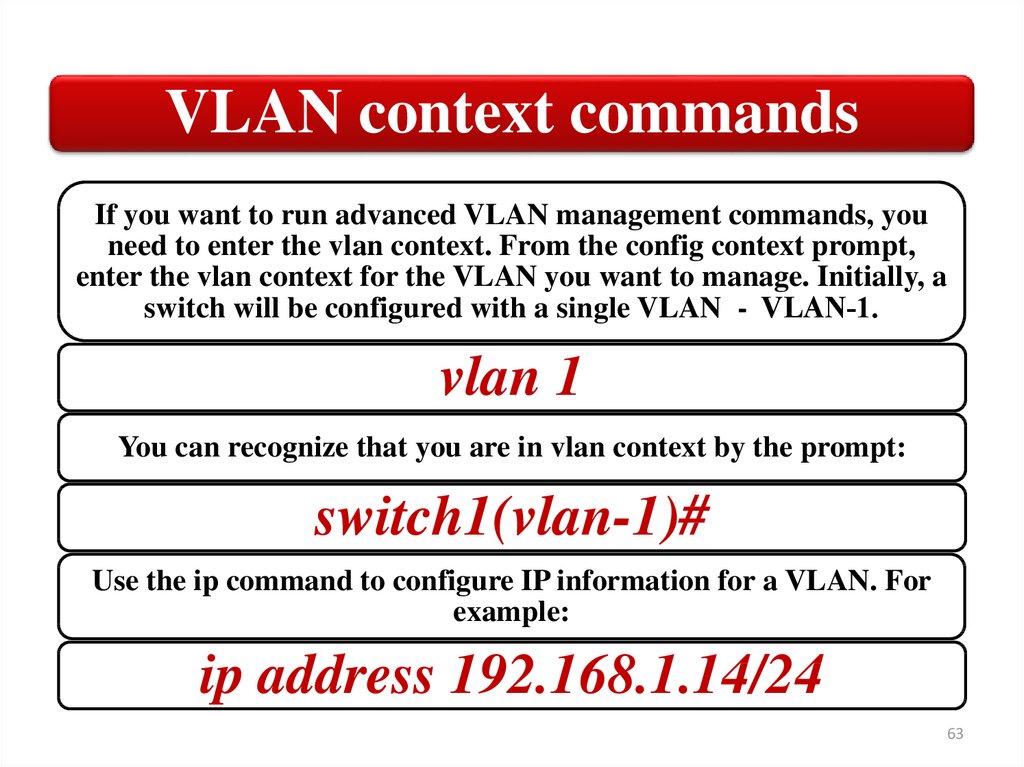
VLAN context commandsIf you want to run advanced VLAN management commands, you
need to enter the vlan context. From the config context prompt,
enter the vlan context for the VLAN you want to manage. Initially, a
switch will be configured with a single VLAN - VLAN‐1.
vlan 1
You can recognize that you are in vlan context by the prompt:
switch1(vlan-1)#
Use the ip command to configure IP information for a VLAN. For
example:
ip address 192.168.1.14/24
63
64.
Save configuration changesAfter making your
configuration changes,
you must save them to
the switch flash
memory. To do this,
run:
• write
memory
64
65.
Command HistoryYou have access to recently run commands in case you need
to use them again. To view the command history list, run:
show history
65
66.
Command HistoryYou can press the up and down arrows to
scroll through commands history list. You can
edit the command line, if necessary, and press
the Enter key to execute the command again.
You can execute a command from the command
history by its index number. For example:
repeat 10
66
67.
Summary• Operator level
Command • Manager level
line
• Global
interface
configuration level
(CLI)
• VLAN context
configuration level
67
68.
HardwareFundamentals
4. Menu interface
68
69.
Menu interfaceThe menu interface is easier to use
because you select commands from
a menu instead of typing them.
However, the menu interface limits
the management commands to
which you have access.
69
70.
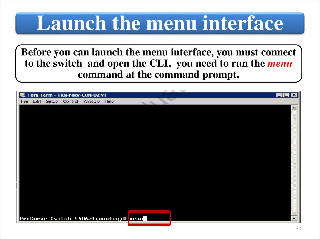
Launch the menu interfaceBefore you can launch the menu interface, you must connect
to the switch and open the CLI, you need to run the menu
command at the command prompt.
70
71.
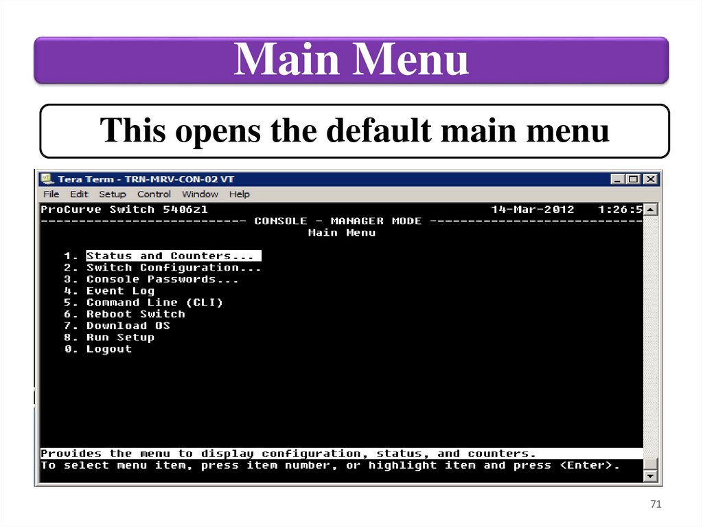
Main MenuThis opens the default main menu
71
72.
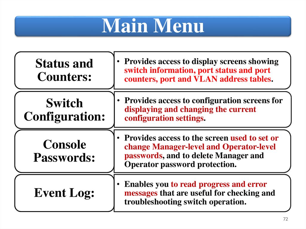
Main MenuStatus and
Counters:
• Provides access to display screens showing
switch information, port status and port
counters, port and VLAN address tables.
Switch
Configuration:
• Provides access to configuration screens for
displaying and changing the current
configuration settings.
Console
Passwords:
• Provides access to the screen used to set or
change Manager-level and Operator-level
passwords, and to delete Manager and
Operator password protection.
Event Log:
• Enables you to read progress and error
messages that are useful for checking and
troubleshooting switch operation.
72
73.
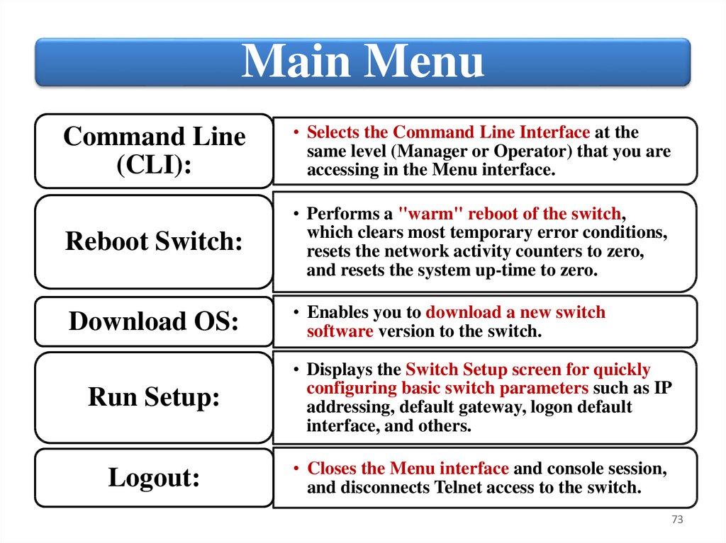
Main MenuCommand Line
(CLI):
• Selects the Command Line Interface at the
same level (Manager or Operator) that you are
accessing in the Menu interface.
Reboot Switch:
• Performs a "warm" reboot of the switch,
which clears most temporary error conditions,
resets the network activity counters to zero,
and resets the system up-time to zero.
Download OS:
• Enables you to download a new switch
software version to the switch.
Run Setup:
• Displays the Switch Setup screen for quickly
configuring basic switch parameters such as IP
addressing, default gateway, logon default
interface, and others.
Logout:
• Closes the Menu interface and console session,
and disconnects Telnet access to the switch.
73
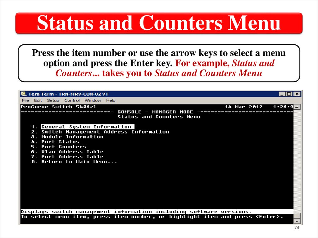
74.
Status and Counters MenuPress the item number or use the arrow keys to select a menu
option and press the Enter key. For example, Status and
Counters... takes you to Status and Counters Menu
74
75.
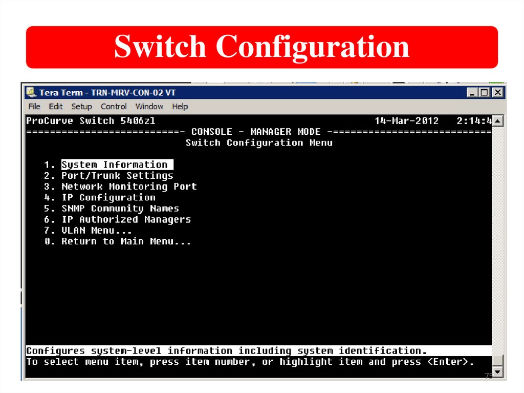
Switch Configuration75
76.
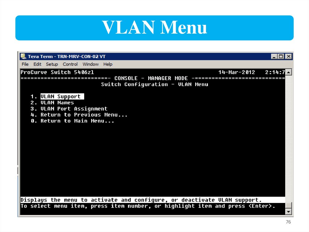
VLAN Menu76
77.
VLAN Menu – VLAN Names77
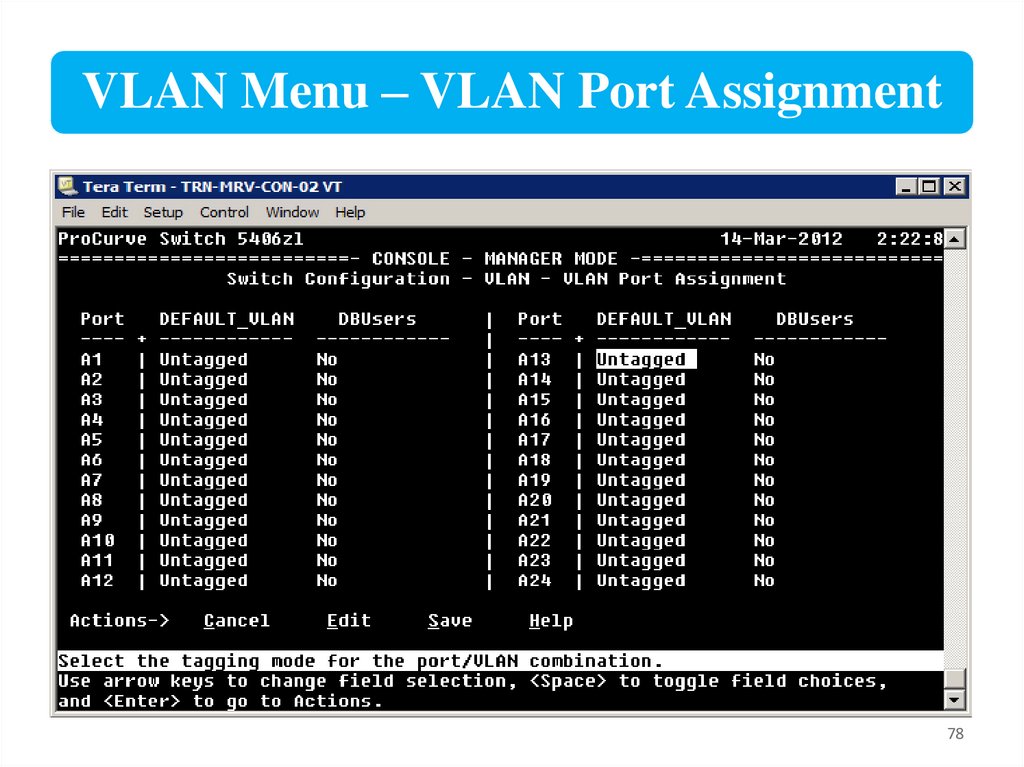
78.
VLAN Menu – VLAN Port Assignment78
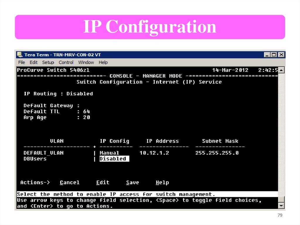
79.
IP Configuration79
80.
Operator Default MenuIf you launch the menu interface from an operator
CLI prompt, you are presented with a much more
limited menu selection.
80
81.
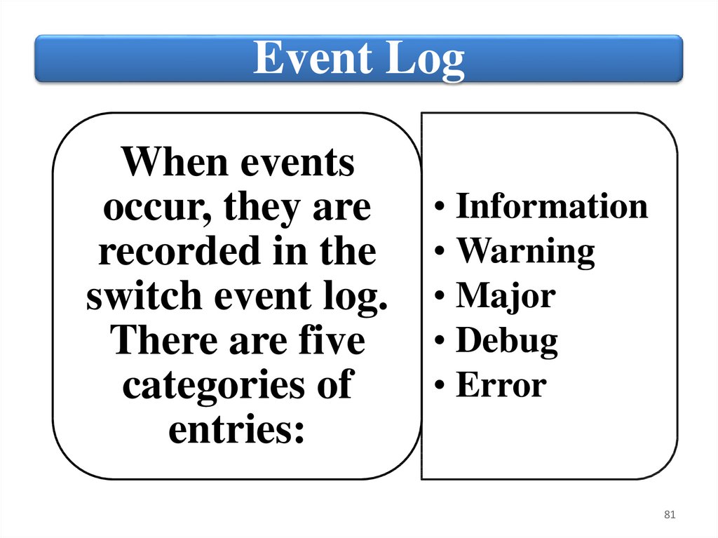
Event LogWhen events
occur, they are
recorded in the
switch event log.
There are five
categories of
entries:
• Information
• Warning
• Major
• Debug
• Error
81
82.
To view the event log in the CLI, run:Show logging
82
83.
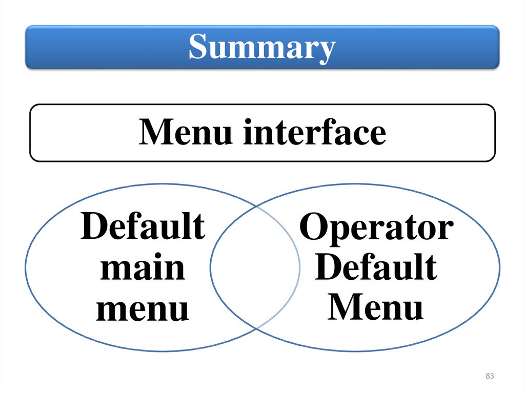
SummaryMenu interface
Default
main
menu
Operator
Default
Menu
83