

 internet
Similar presentations:


Routing Introduction
1.
Lecture 5Routing & VRRP
1
2.
Objectives1. Routing Introduction
2. Inter-VLAN Routing
3. Configuring Inter-VLAN Routing
4. Virtual Router Redundancy Protocol
(VRRP)
5. Deploying VRRP
2
3.
Routing & VRRP1. Routing Introduction
3
4.
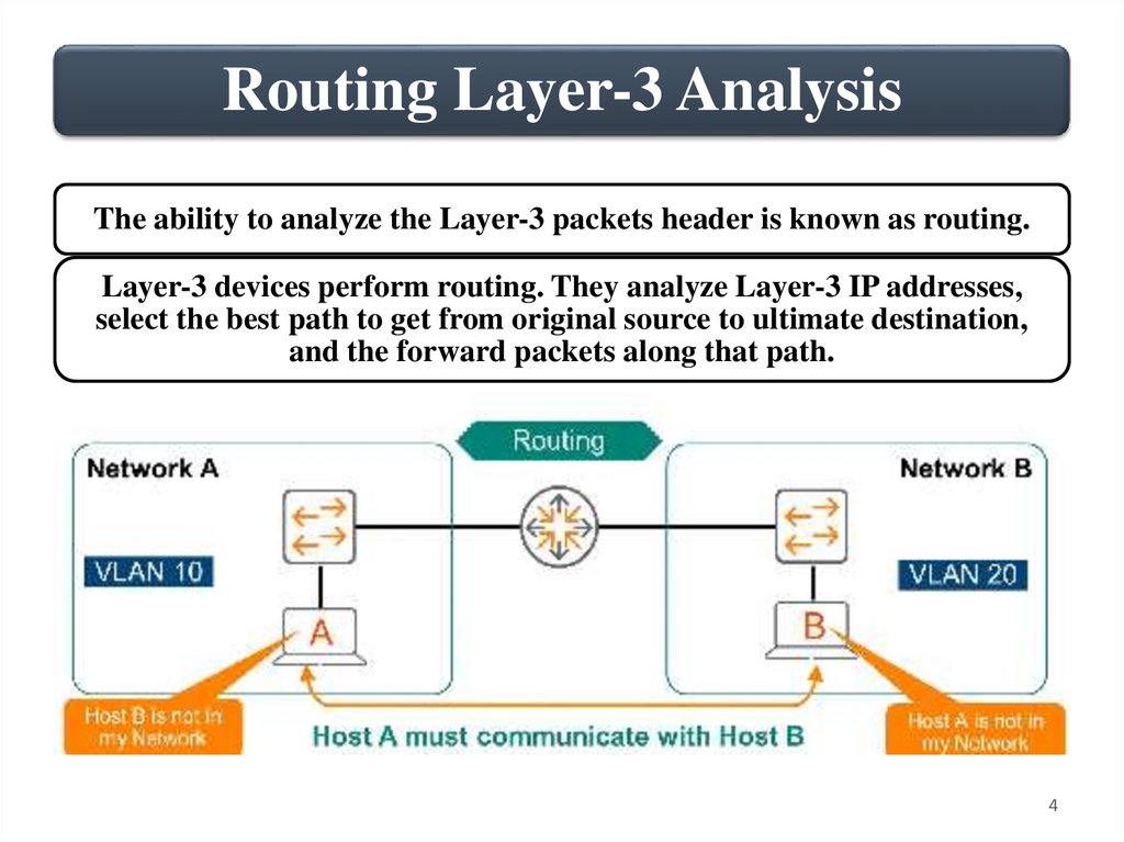
Routing Layer-3 AnalysisThe ability to analyze the Layer-3 packets header is known as routing.
Layer-3 devices perform routing. They analyze Layer-3 IP addresses,
select the best path to get from original source to ultimate destination,
and the forward packets along that path.
4
5.
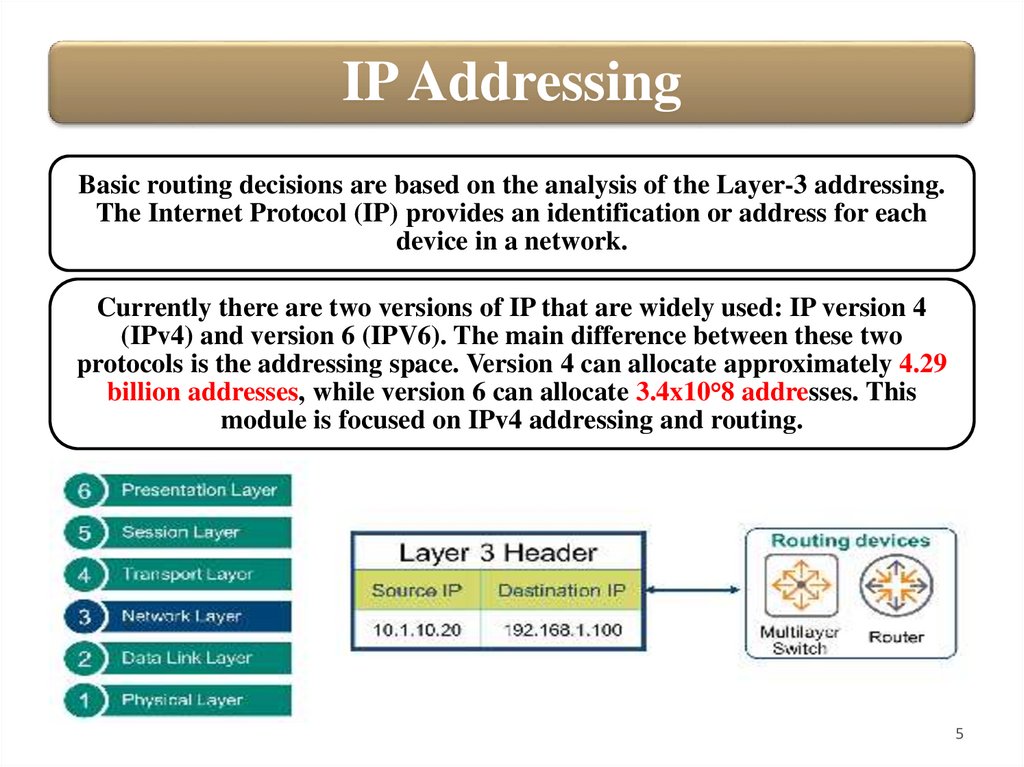
IP AddressingBasic routing decisions are based on the analysis of the Layer-3 addressing.
The Internet Protocol (IP) provides an identification or address for each
device in a network.
Currently there are two versions of IP that are widely used: IP version 4
(IPv4) and version 6 (IPV6). The main difference between these two
protocols is the addressing space. Version 4 can allocate approximately 4.29
billion addresses, while version 6 can allocate 3.4x10°8 addresses. This
module is focused on IPv4 addressing and routing.
5
6.
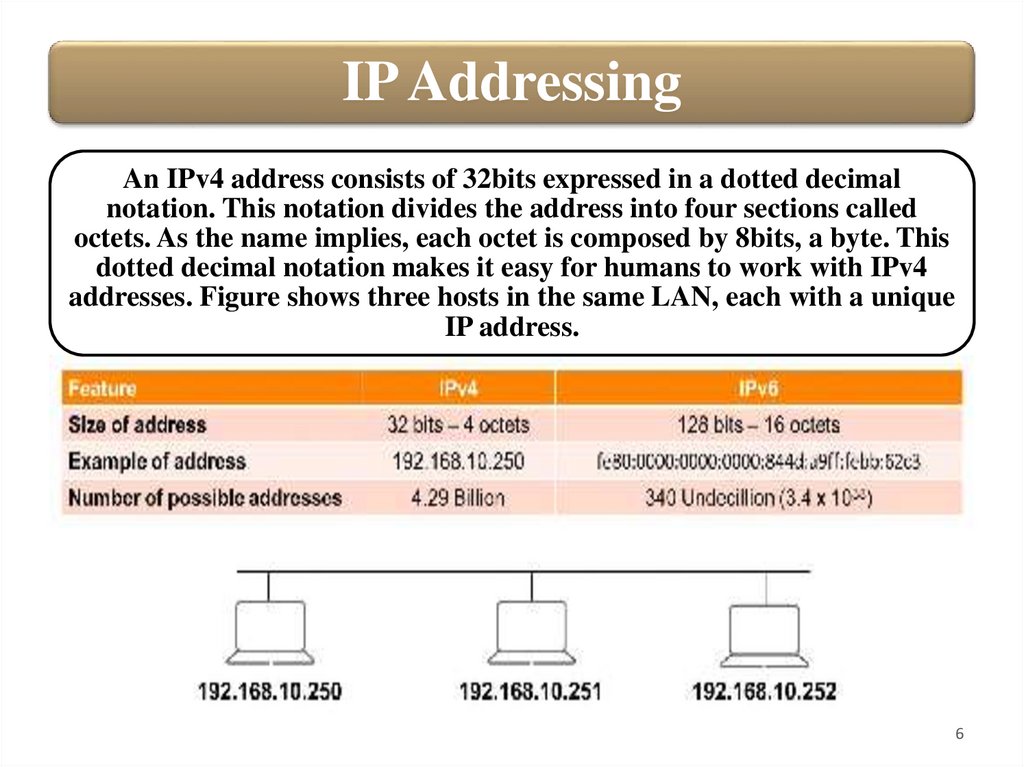
IP AddressingAn IPv4 address consists of 32bits expressed in a dotted decimal
notation. This notation divides the address into four sections called
octets. As the name implies, each octet is composed by 8bits, a byte. This
dotted decimal notation makes it easy for humans to work with IPv4
addresses. Figure shows three hosts in the same LAN, each with a unique
IP address.
6
7.
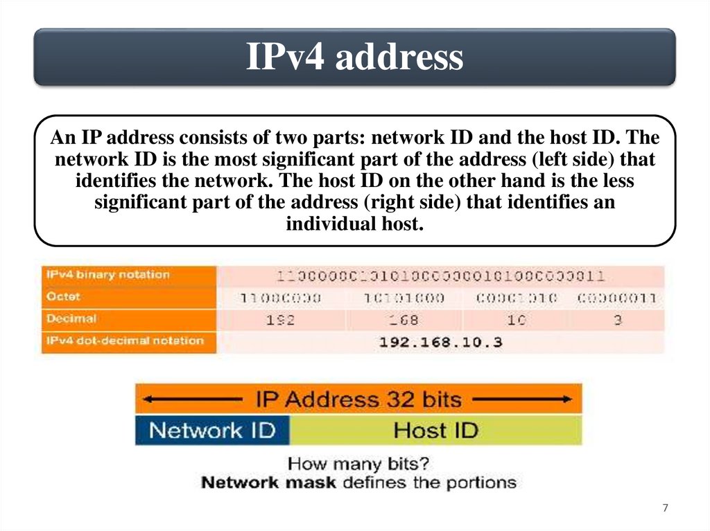
IPv4 addressAn IP address consists of two parts: network ID and the host ID. The
network ID is the most significant part of the address (left side) that
identifies the network. The host ID on the other hand is the less
significant part of the address (right side) that identifies an
individual host.
7
8.
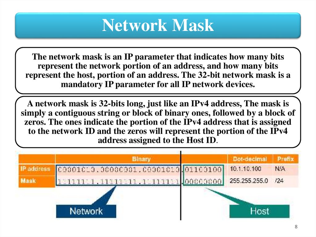
Network MaskThe network mask is an IP parameter that indicates how many bits
represent the network portion of an address, and how many bits
represent the host, portion of an address. The 32-bit network mask is a
mandatory IP parameter for all IP network devices.
A network mask is 32-bits long, just like an IPv4 address, The mask is
simply a contiguous string or block of binary ones, followed by a block of
zeros. The ones indicate the portion of the IPv4 address that is assigned
to the network ID and the zeros will represent the portion of the IPv4
address assigned to the Host ID.
8
9.
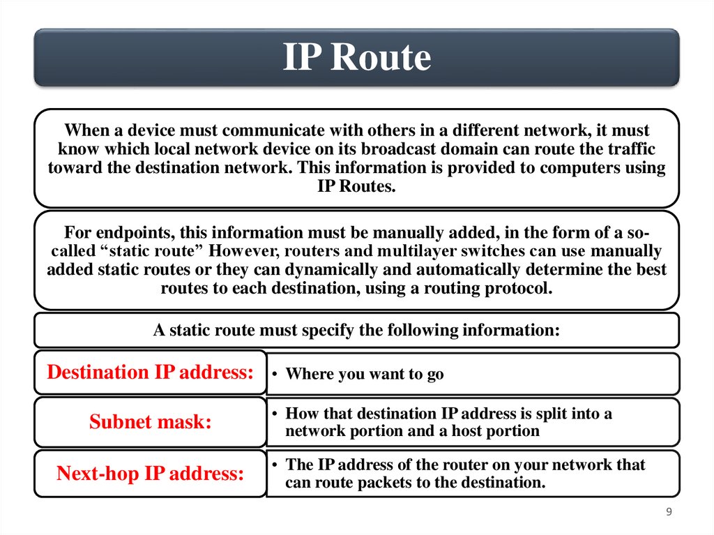
IP RouteWhen a device must communicate with others in a different network, it must
know which local network device on its broadcast domain can route the traffic
toward the destination network. This information is provided to computers using
IP Routes.
For endpoints, this information must be manually added, in the form of a socalled “static route” However, routers and multilayer switches can use manually
added static routes or they can dynamically and automatically determine the best
routes to each destination, using a routing protocol.
A static route must specify the following information:
Destination IP address: • Where you want to go
Subnet mask:
Next-hop IP address:
• How that destination IP address is split into a
network portion and a host portion
• The IP address of the router on your network that
can route packets to the destination.
9
10.
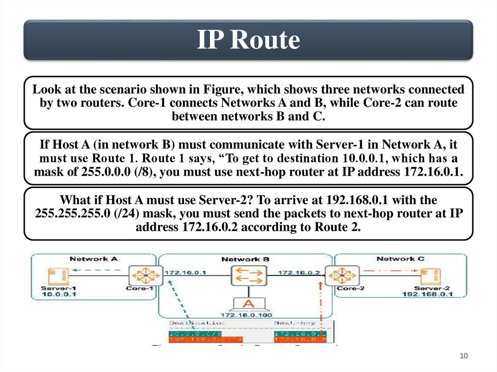
IP RouteLook at the scenario shown in Figure, which shows three networks connected
by two routers. Core-1 connects Networks A and B, while Core-2 can route
between networks B and C.
If Host A (in network B) must communicate with Server-1 in Network A, it
must use Route 1. Route 1 says, “To get to destination 10.0.0.1, which has a
mask of 255.0.0.0 (/8), you must use next-hop router at IP address 172.16.0.1.
What if Host A must use Server-2? To arrive at 192.168.0.1 with the
255.255.255.0 (/24) mask, you must send the packets to next-hop router at IP
address 172.16.0.2 according to Route 2.
10
11.
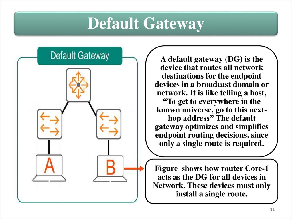
Default GatewayA default gateway (DG) is the
device that routes all network
destinations for the endpoint
devices in a broadcast domain or
network. It is like telling a host,
“To get to everywhere in the
known universe, go to this nexthop address” The default
gateway optimizes and simplifies
endpoint routing decisions, since
only a single route is required.
Figure shows how router Core-1
acts as the DG for all devices in
Network. These devices must only
install a single route.
11
12.
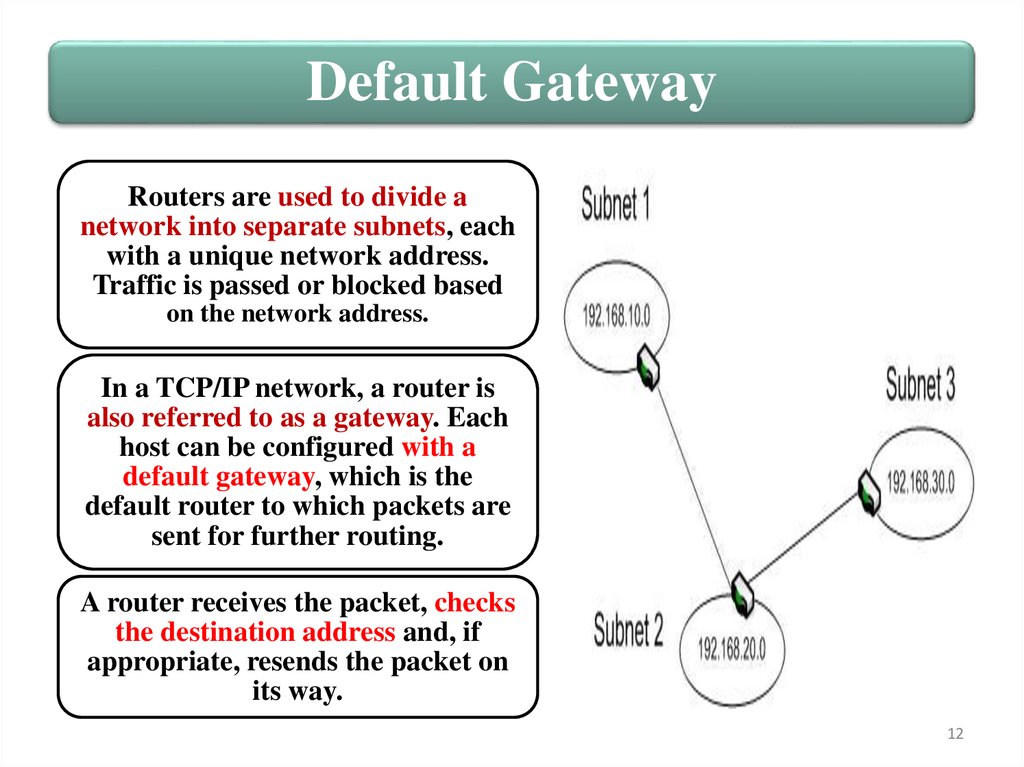
Default GatewayRouters are used to divide a
network into separate subnets, each
with a unique network address.
Traffic is passed or blocked based
on the network address.
In a TCP/IP network, a router is
also referred to as a gateway. Each
host can be configured with a
default gateway, which is the
default router to which packets are
sent for further routing.
A router receives the packet, checks
the destination address and, if
appropriate, resends the packet on
its way.
12
13.
Routing & VRRP2. Inter-VLAN Routing
13
14.
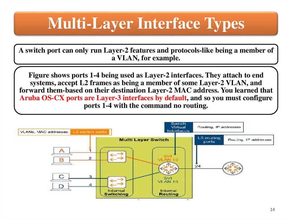
Multi-Layer Interface TypesA switch port can only run Layer-2 features and protocols-like being a member of
a VLAN, for example.
Figure shows ports 1-4 being used as Layer-2 interfaces. They attach to end
systems, accept L2 frames as being a member of some Layer-2 VLAN, and
forward them-based on their destination Layer-2 MAC address. You learned that
Aruba OS-CX ports are Layer-3 interfaces by default, and so you must configure
ports 1-4 with the command no routing.
14
15.
Multi-Layer Interface TypesBut what if you want to route between these VLANs. The Aruba OS-CX
switches are multi-layer switches; they have both internal Layer-2 switching
functions and internal Layer-3 routing capabilities. You need a way to
connect each Layer-2 VLAN to the internal routing functions.
To do this, you must create Switch Virtual Interfaces (SVI). This is a virtual
Layer-3, routed interface that exists only inside the device, as a virtual
construct.
Suppose that you define SVI 10. Because it is an SVI, by definition, it
connects to the internal routing construct. Because it is SVI “10”, by
definition, it connects to VLAN 10, and so services routable traffic from
VLAN 10 to other destination networks.
Similarly, you might define SVI 20. With some routing configuration, which
you will soon learn, your switch can now route traffic between your VLANs.
15
16.
Multi-Layer Interface TypesNow suppose that you need to connect your multi-Layer switch to an
external router, perhaps using port 24, as shown in Figure above. Since
all ports are Layer-3 interfaces by default, Port 24 connects to the
internal routing functions by default. You merely need to configure it
with typical Layer-3 parameters, such as an IP address. You will soon
learn about these concepts and syntax.
The SVIs are virtual Layer-3 interfaces, for internal routing, and port 24
is a physical Layer-3 interface, for external routing. Both are Layer-3
interfaces, and so perform routing functions. They accept routable
Layer-3 packets and forward them based on their destination IP address.
Now you know about three important interface types, L2 switch ports,
L3 SVIs, and L3 physical routed ports. You are ready to learn about
another especially important interface type: a trunk port.
16
17.
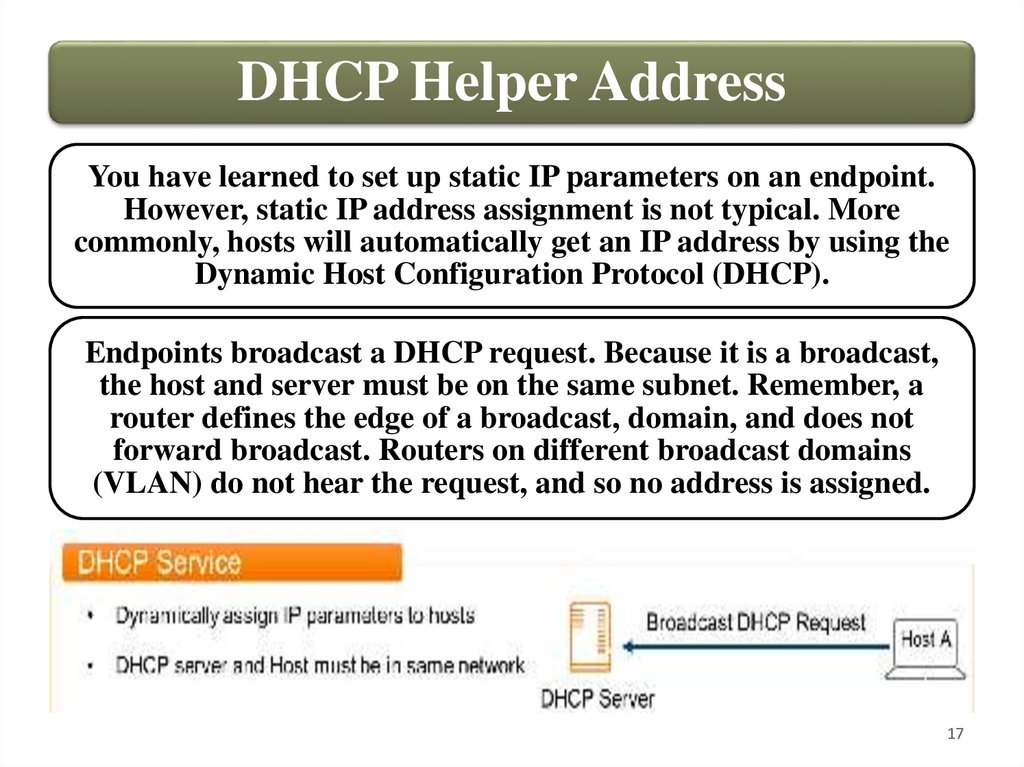
DHCP Helper AddressYou have learned to set up static IP parameters on an endpoint.
However, static IP address assignment is not typical. More
commonly, hosts will automatically get an IP address by using the
Dynamic Host Configuration Protocol (DHCP).
Endpoints broadcast a DHCP request. Because it is a broadcast,
the host and server must be on the same subnet. Remember, a
router defines the edge of a broadcast, domain, and does not
forward broadcast. Routers on different broadcast domains
(VLAN) do not hear the request, and so no address is assigned.
17
18.
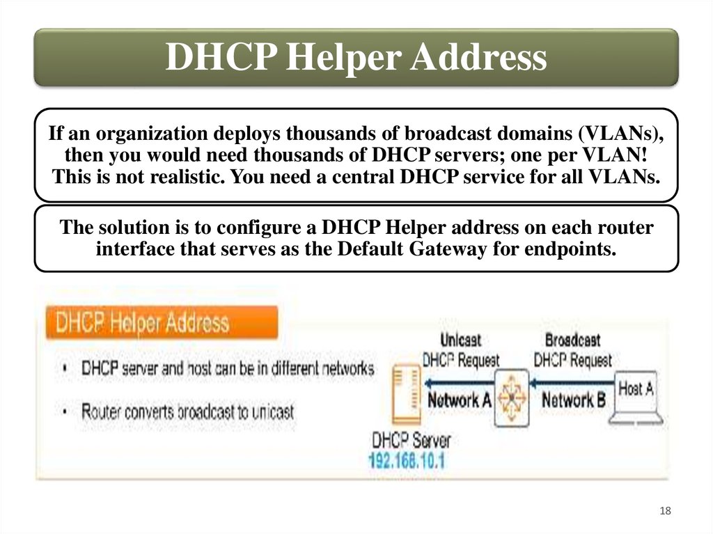
DHCP Helper AddressIf an organization deploys thousands of broadcast domains (VLANs),
then you would need thousands of DHCP servers; one per VLAN!
This is not realistic. You need a central DHCP service for all VLANs.
The solution is to configure a DHCP Helper address on each router
interface that serves as the Default Gateway for endpoints.
18
19.
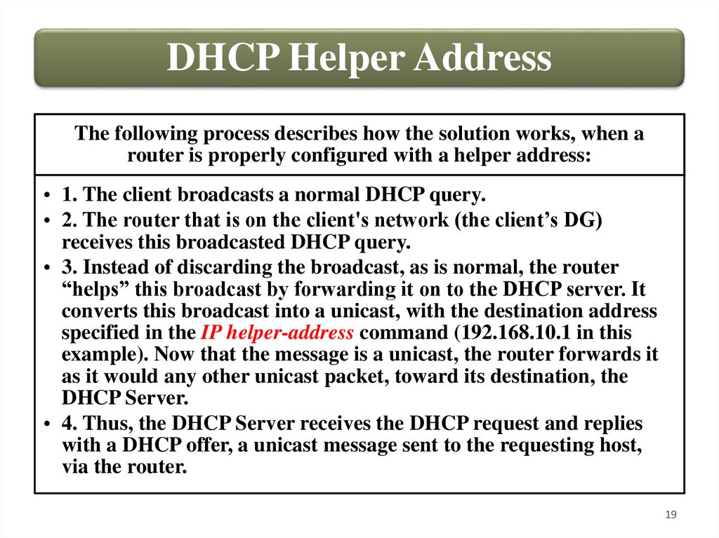
DHCP Helper AddressThe following process describes how the solution works, when a
router is properly configured with a helper address:
• 1. The client broadcasts a normal DHCP query.
• 2. The router that is on the client's network (the client’s DG)
receives this broadcasted DHCP query.
• 3. Instead of discarding the broadcast, as is normal, the router
“helps” this broadcast by forwarding it on to the DHCP server. It
converts this broadcast into a unicast, with the destination address
specified in the IP helper-address command (192.168.10.1 in this
example). Now that the message is a unicast, the router forwards it
as it would any other unicast packet, toward its destination, the
DHCP Server.
• 4. Thus, the DHCP Server receives the DHCP request and replies
with a DHCP offer, a unicast message sent to the requesting host,
via the router.
19
20.
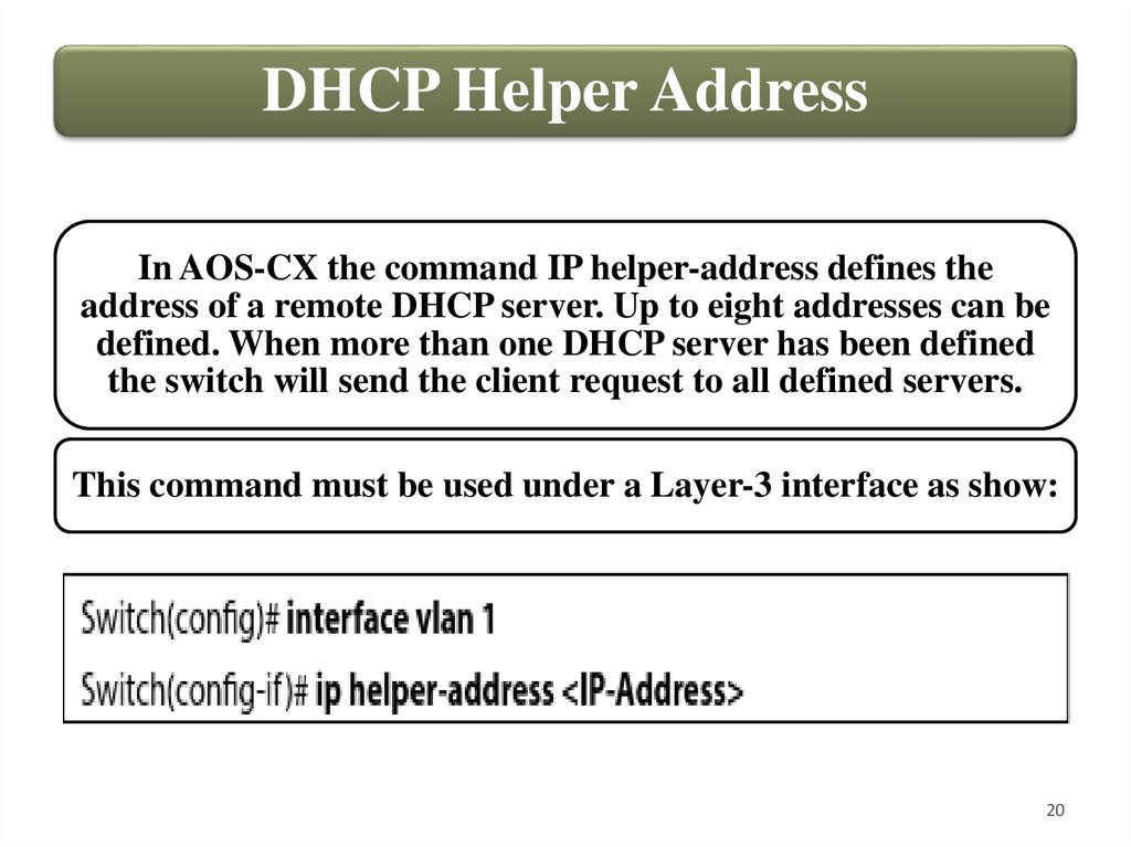
DHCP Helper AddressIn AOS-CX the command IP helper-address defines the
address of a remote DHCP server. Up to eight addresses can be
defined. When more than one DHCP server has been defined
the switch will send the client request to all defined servers.
This command must be used under a Layer-3 interface as show:
20
21.
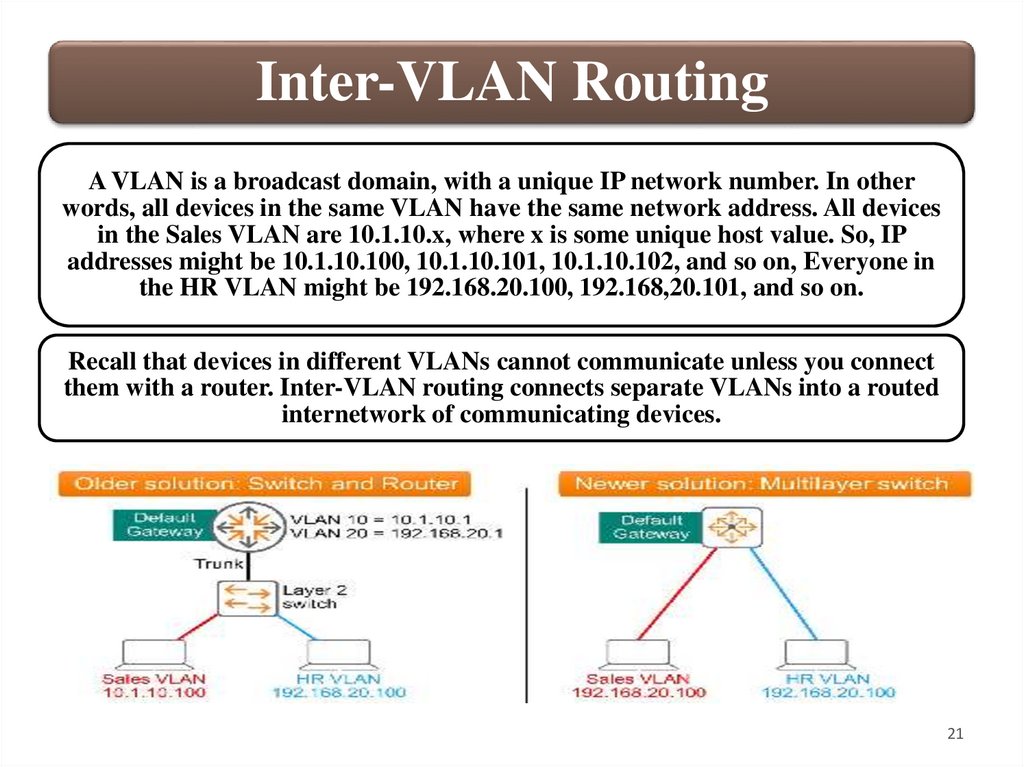
Inter-VLAN RoutingA VLAN is a broadcast domain, with a unique IP network number. In other
words, all devices in the same VLAN have the same network address. All devices
in the Sales VLAN are 10.1.10.x, where x is some unique host value. So, IP
addresses might be 10.1.10.100, 10.1.10.101, 10.1.10.102, and so on, Everyone in
the HR VLAN might be 192.168.20.100, 192.168,20.101, and so on.
Recall that devices in different VLANs cannot communicate unless you connect
them with a router. Inter-VLAN routing connects separate VLANs into a routed
internetwork of communicating devices.
21
22.
Inter-VLAN RoutingA potential problem with this deployment is that the Switch-torouter link can become oversubscribe, although LAG can
alleviate this problem to some extent. Performance can also be
suboptimal, because sending frames to the router requires an
additional routing decision.
Multilayer switches are more efficient devices. The switching and
routing functions of the device are connected via a high-speed
internal backplane. Initial routing decisions and other processes
all happen “in the box”. This can reduce latency and increase
performance.
All AOS-CX switches are multilayer switches which have routing
enabled by default.
22
23.
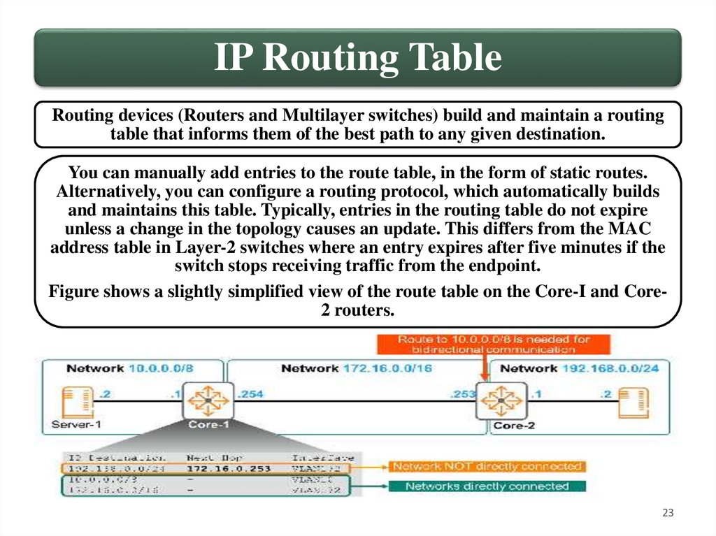
IP Routing TableRouting devices (Routers and Multilayer switches) build and maintain a routing
table that informs them of the best path to any given destination.
You can manually add entries to the route table, in the form of static routes.
Alternatively, you can configure a routing protocol, which automatically builds
and maintains this table. Typically, entries in the routing table do not expire
unless a change in the topology causes an update. This differs from the MAC
address table in Layer-2 switches where an entry expires after five minutes if the
switch stops receiving traffic from the endpoint.
Figure shows a slightly simplified view of the route table on the Core-I and Core2 routers.
23
24.
IP Routing TableThere are three networks, 10.0.0.0/8, 172.16.0.0/16, and
192.168.0.0/24. Recall that the subnet mask determines the network
portion of an IP address.
OK, now let us analyze Core-1’s route table. The first entry says, “To
get to any host on network 192.168.0.0/24, send packets to next-hop
router 172.16.0.253 (Core-2). To get to that next-hop address,
forward the packet, out local VLAN172”
The next entry says, “To get to any host on network 10.0.0.0/8, there
is no next-hop. I am directly connected to that network. Simply
forward the packet out my local VLAN interface 10. Finally, to
connect to the network 172.16.0.0/16, Core-1 is directly connected to
this network. There is no need to assign a next-hop; simple forward
the packet out of VLAN interface 172.
24
25.
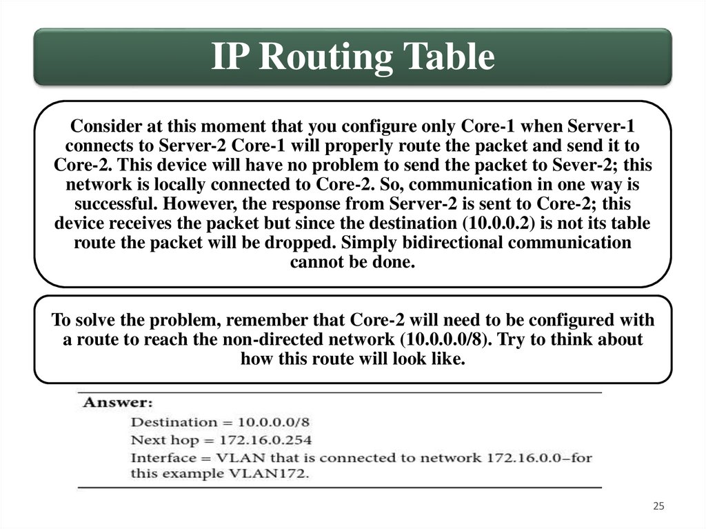
IP Routing TableConsider at this moment that you configure only Core-1 when Server-1
connects to Server-2 Core-1 will properly route the packet and send it to
Core-2. This device will have no problem to send the packet to Sever-2; this
network is locally connected to Core-2. So, communication in one way is
successful. However, the response from Server-2 is sent to Core-2; this
device receives the packet but since the destination (10.0.0.2) is not its table
route the packet will be dropped. Simply bidirectional communication
cannot be done.
To solve the problem, remember that Core-2 will need to be configured with
a route to reach the non-directed network (10.0.0.0/8). Try to think about
how this route will look like.
25
26.
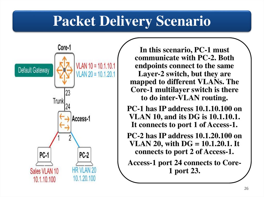
Packet Delivery ScenarioIn this scenario, PC-1 must
communicate with PC-2. Both
endpoints connect to the same
Layer-2 switch, but they are
mapped to different VLANs. The
Core-1 multilayer switch is there
to do inter-VLAN routing.
PC-1 has IP address 10.1.10.100 on
VLAN 10, and its DG is 10.1.10.1.
It connects to port 1 of Access-1.
PC-2 has IP address 10.1.20.100 on
VLAN 20, with DG = 10.1.20.1. It
connects to port 2 of Access-1.
Access-1 port 24 connects to Core1 port 23.
26
27.
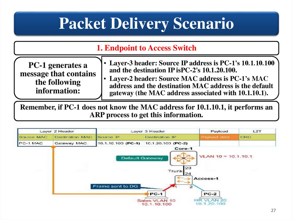
Packet Delivery Scenario1. Endpoint to Access Switch
• Layer-3 header: Source IP address is PC-1’s 10.1.10.100
PC-1 generates a
and the destination IP isPC-2's 10.1.20.100.
message that contains
• Layer-2 header: Source MAC address is PC-1’s MAC
the following
address and the destination MAC address is the default
information:
gateway (the MAC address associated with 10.1.10.1).
Remember, if PC-1 does not know the MAC address for 10.1.10.1, it performs an
ARP process to get this information.
27
28.
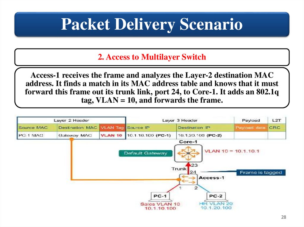
Packet Delivery Scenario2. Access to Multilayer Switch
Access-1 receives the frame and analyzes the Layer-2 destination MAC
address. It finds a match in its MAC address table and knows that it must
forward this frame out its trunk link, port 24, to Core-1. It adds an 802.1q
tag, VLAN = 10, and forwards the frame.
28
29.
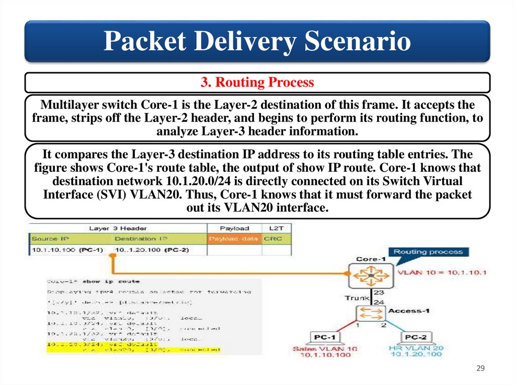
Packet Delivery Scenario3. Routing Process
Multilayer switch Core-1 is the Layer-2 destination of this frame. It accepts the
frame, strips off the Layer-2 header, and begins to perform its routing function, to
analyze Layer-3 header information.
It compares the Layer-3 destination IP address to its routing table entries. The
figure shows Core-1's route table, the output of show IP route. Core-1 knows that
destination network 10.1.20.0/24 is directly connected on its Switch Virtual
Interface (SVI) VLAN20. Thus, Core-1 knows that it must forward the packet
out its VLAN20 interface.
29
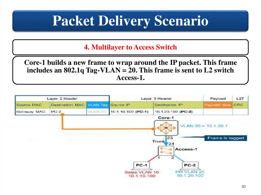
30.
Packet Delivery Scenario4. Multilayer to Access Switch
Core-1 builds a new frame to wrap around the IP packet. This frame
includes an 802.1q Tag-VLAN = 20. This frame is sent to L2 switch
Access-1.
30
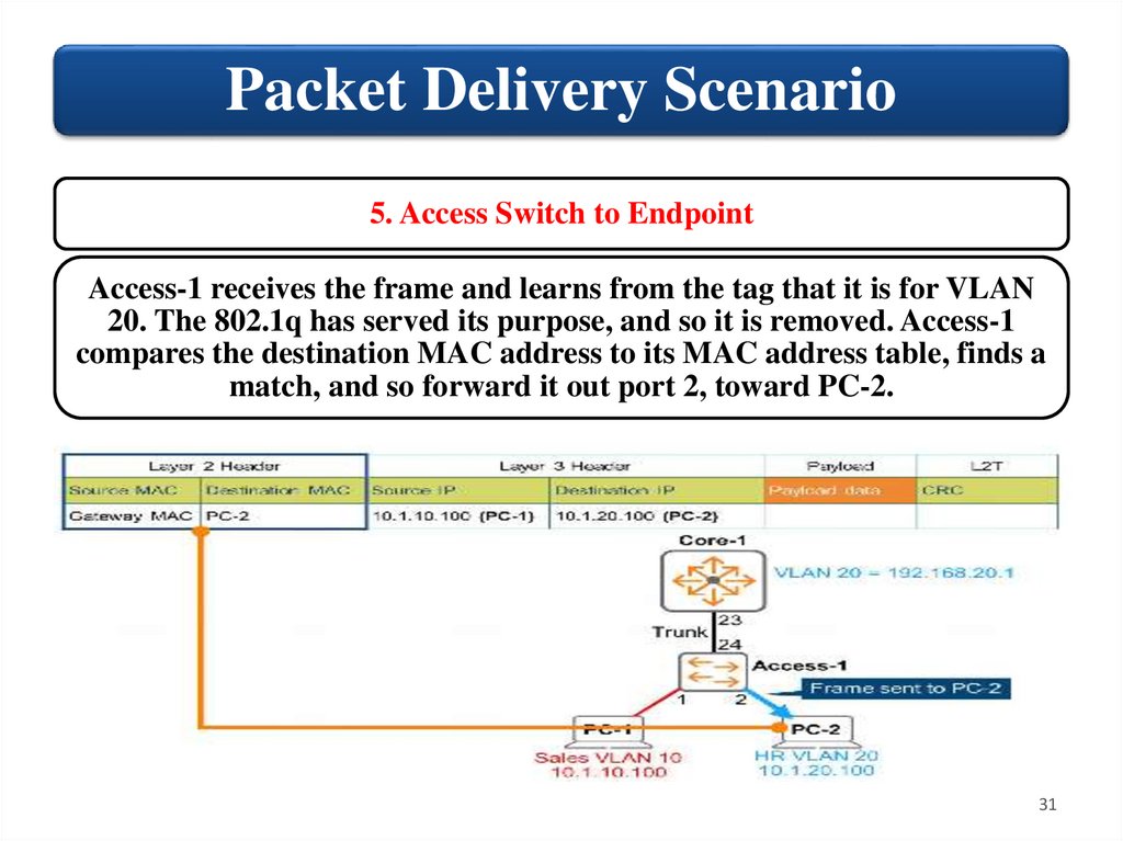
31.
Packet Delivery Scenario5. Access Switch to Endpoint
Access-1 receives the frame and learns from the tag that it is for VLAN
20. The 802.1q has served its purpose, and so it is removed. Access-1
compares the destination MAC address to its MAC address table, finds a
match, and so forward it out port 2, toward PC-2.
31
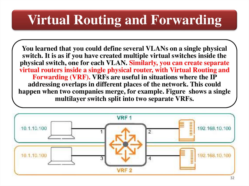
32.
Virtual Routing and ForwardingYou learned that you could define several VLANs on a single physical
switch. It is as if you have created multiple virtual switches inside the
physical switch, one for each VLAN. Similarly, you can create separate
virtual routers inside a single physical router, with Virtual Routing and
Forwarding (VRF). VRFs are useful in situations where the IP
addressing overlaps in different places of the network. This could
happen when two companies merge, for example. Figure shows a single
multilayer switch split into two separate VRFs.
32
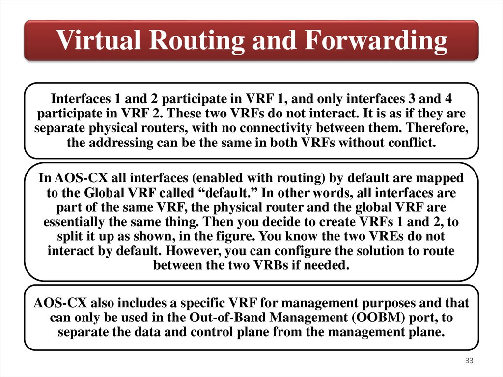
33.
Virtual Routing and ForwardingInterfaces 1 and 2 participate in VRF 1, and only interfaces 3 and 4
participate in VRF 2. These two VRFs do not interact. It is as if they are
separate physical routers, with no connectivity between them. Therefore,
the addressing can be the same in both VRFs without conflict.
In AOS-CX all interfaces (enabled with routing) by default are mapped
to the Global VRF called “default.” In other words, all interfaces are
part of the same VRF, the physical router and the global VRF are
essentially the same thing. Then you decide to create VRFs 1 and 2, to
split it up as shown, in the figure. You know the two VREs do not
interact by default. However, you can configure the solution to route
between the two VRBs if needed.
AOS-CX also includes a specific VRF for management purposes and that
can only be used in the Out-of-Band Management (OOBM) port, to
separate the data and control plane from the management plane.
33
34.
Routing & VRRP3. Configuring Inter-VLAN
Routing
34
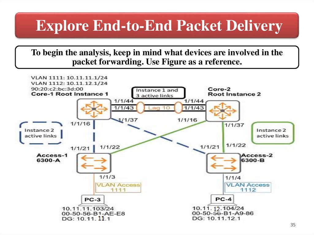
35.
Explore End-to-End Packet DeliveryTo begin the analysis, keep in mind what devices are involved in the
packet forwarding. Use Figure as a reference.
35
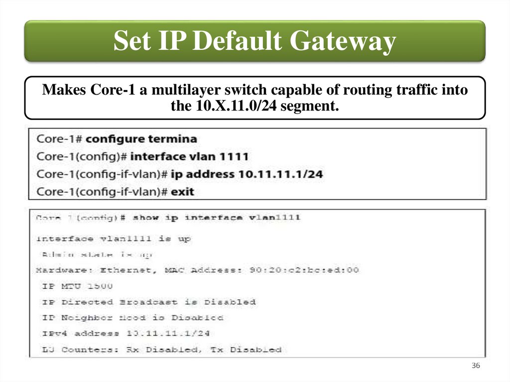
36.
Set IP Default GatewayMakes Core-1 a multilayer switch capable of routing traffic into
the 10.X.11.0/24 segment.
36
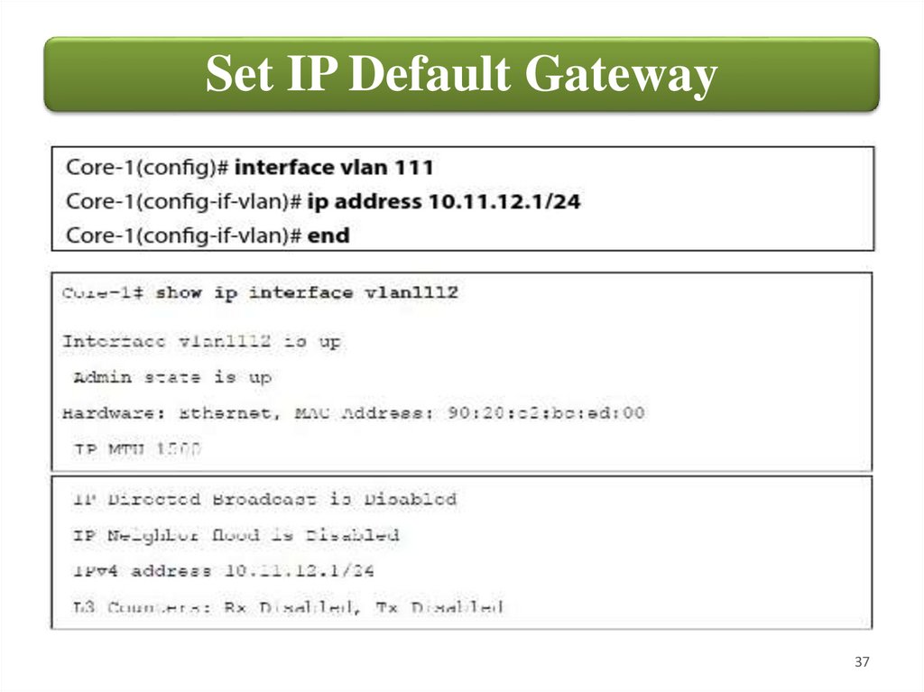
37.
Set IP Default Gateway37
38.
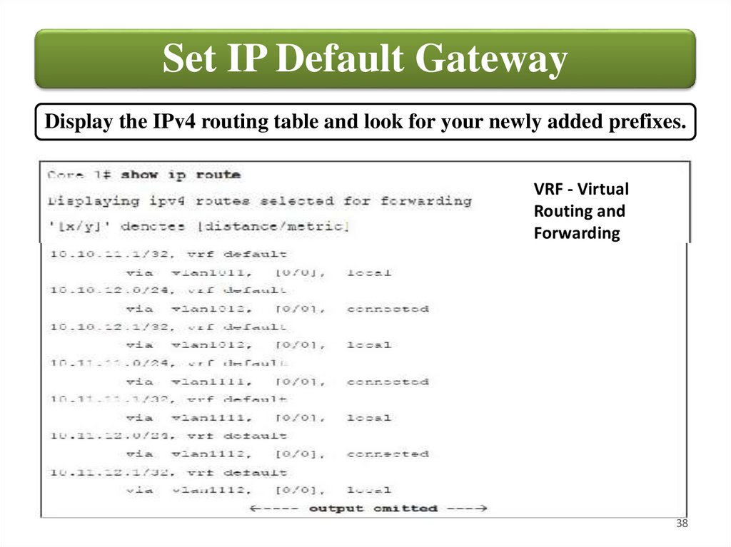
Set IP Default GatewayDisplay the IPv4 routing table and look for your newly added prefixes.
VRF - Virtual
Routing and
Forwarding
38
39.
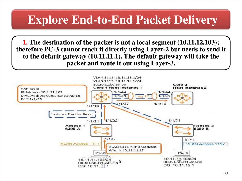
Explore End-to-End Packet Delivery1. The destination of the packet is not a local segment (10.11.12.103);
therefore PC-3 cannot reach it directly using Layer-2 but needs to send it
to the default gateway (10.11.11.1). The default gateway will take the
packet and route it out using Layer-3.
39
40.
Explore End-to-End Packet DeliveryTo do this, PC-3 must take the ICMP echo request (from the
ping command) and return it to Core-1 on VLAN 1111. The IP
header of the ICMP Echo request will remain untouched;
however it must be encapsulated with an Ethernet Layer-2
header to forward it.
To achieve this, PC-3 needs to know Core-1’s MAC address so
it can complete the Ethernet header generation. This process
is known as Layer-3 to Layer-2 address resolution and
requires ARP. Since you initially deleted PC-3's ARP table, it
must send out an ARP request first; this packet uses the
broadcast destination MAC address to assure it reaches all
devices in the common VLAN.
40
41.
Explore End-to-End Packet DeliveryWhen the broadcast is received by Access-1, it floods it across all ports
in STP Forwarding mode for VLAN X11 except the sending port (port
3). Even though this is a broadcast packet, Access-2 does not decapsulate
and process it beyond Layer-2 because the Ethertype 0x0806 tells the
switch that an ARP packet will follow. Since ARP is an IP protocol
(Layer-3) and Access-1 is not currently running Layer-3, there is no
reason to keep inspecting the packet.
Core-1 receives the packet on port 1/1/16. Core-1 broadcasts the packet
on all ports in Forwarding mode on VLAN 1111 (port 1/1/37 and LAG
10). When the packet is received by Core-2 and Access-2 they just drop it.
When Core-1 looks at the Ethertype (ARP), it inspects the header at
Layer-3 because IP is running on interface VLAN 1111. After inspecting
the ARP request, Core-1 recognizes the payload is asking for its own IP
and prepares the reply.
41
42.
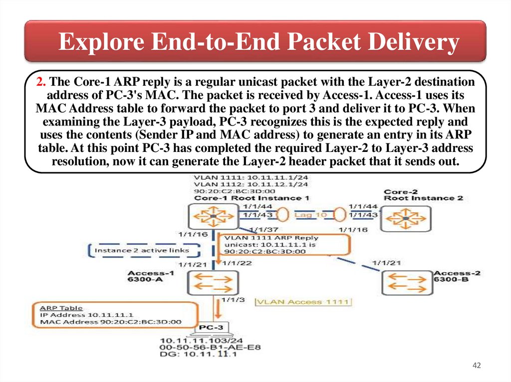
Explore End-to-End Packet Delivery2. The Core-1 ARP reply is a regular unicast packet with the Layer-2 destination
address of PC-3's MAC. The packet is received by Access-1. Access-1 uses its
MAC Address table to forward the packet to port 3 and deliver it to PC-3. When
examining the Layer-3 payload, PC-3 recognizes this is the expected reply and
uses the contents (Sender IP and MAC address) to generate an entry in its ARP
table. At this point PC-3 has completed the required Layer-2 to Layer-3 address
resolution, now it can generate the Layer-2 header packet that it sends out.
42
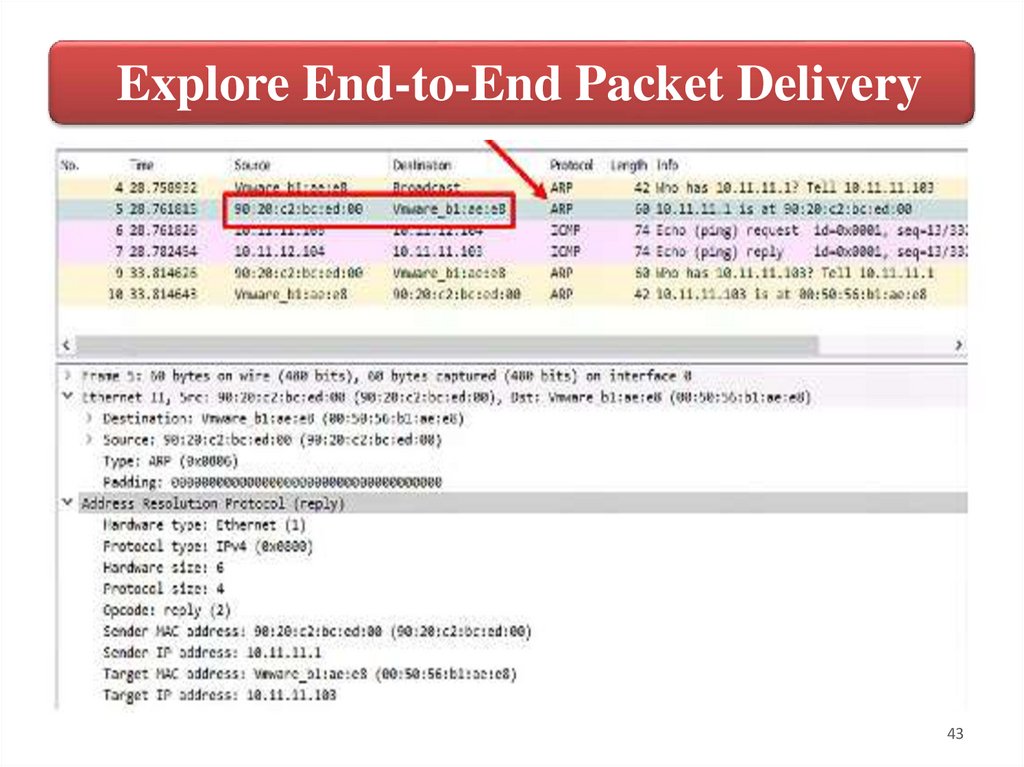
43.
Explore End-to-End Packet Delivery43
44.
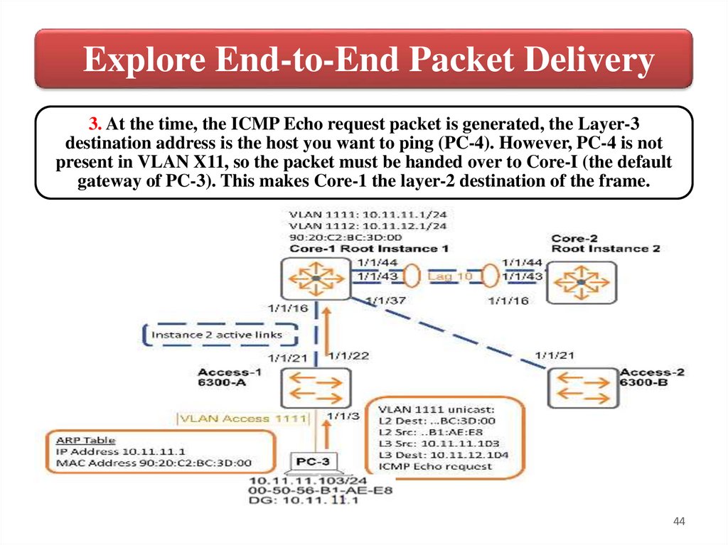
Explore End-to-End Packet Delivery3. At the time, the ICMP Echo request packet is generated, the Layer-3
destination address is the host you want to ping (PC-4). However, PC-4 is not
present in VLAN X11, so the packet must be handed over to Core-I (the default
gateway of PC-3). This makes Core-1 the layer-2 destination of the frame.
44
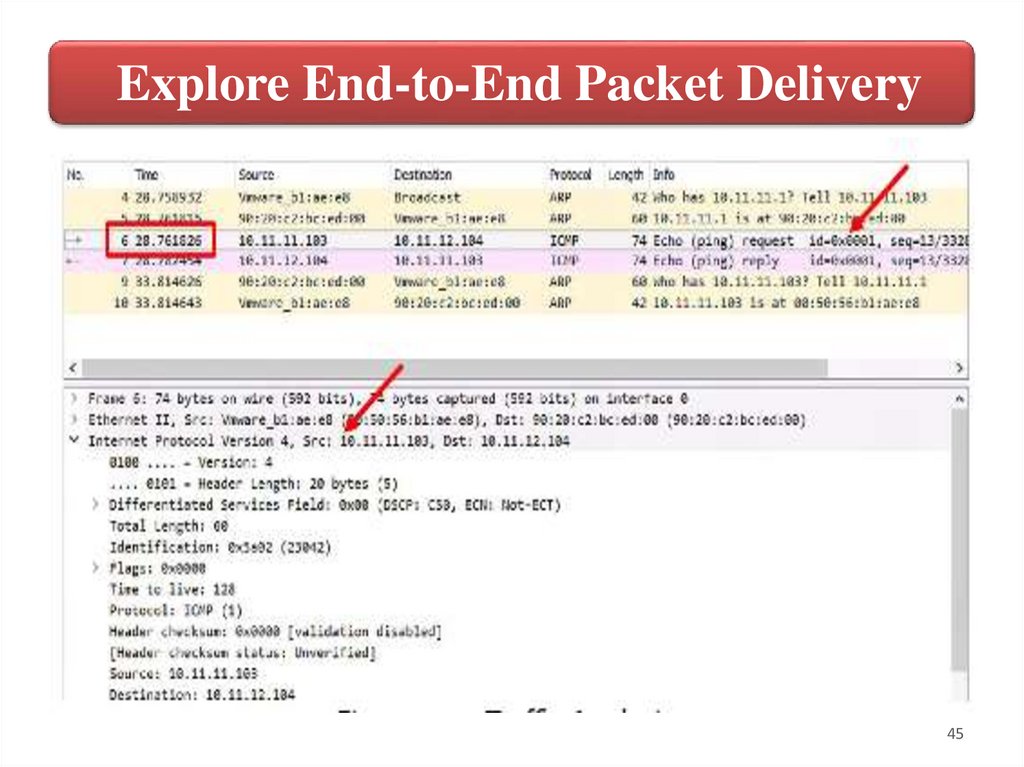
45.
Explore End-to-End Packet Delivery45
46.
Explore End-to-End Packet DeliveryThe following part of the process takes place
on VLAN 1112. Since PC-3 is not part of that
broadcast domain, move to PC-4 and
continue the packet analysis from there..
Move to PC-4.
46
47.
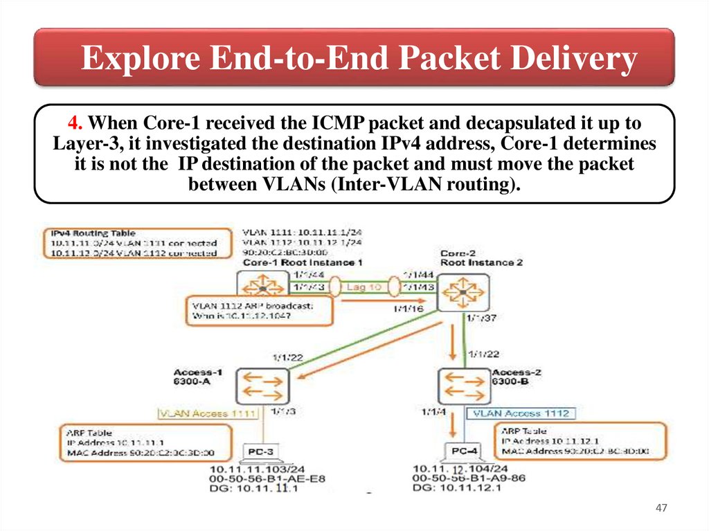
Explore End-to-End Packet Delivery4. When Core-1 received the ICMP packet and decapsulated it up to
Layer-3, it investigated the destination IPv4 address, Core-1 determines
it is not the IP destination of the packet and must move the packet
between VLANs (Inter-VLAN routing).
47
48.
Explore End-to-End Packet DeliveryTo route between VLANs, Core-1 examines its routing
table. It looks for entry with an IP prefix or network
that includes the destination IP address. If several entries
are found, then the longest match (the more specific
route) is used. In the current routing table, there is a
valid entry: 10.X.12.0/24 out of VLAN X12 that Core-1
can use. It is a connected route.
Core-1 is now like PC-3 at the beginning of the process. It
knows which outbound Layer-3 interface to use but it
must create the Layer-2 header; BG: therefore it needs to
perform another Layer-2/Layer-3 address resolution
48
49.
Explore End-to-End Packet Delivery49
50.
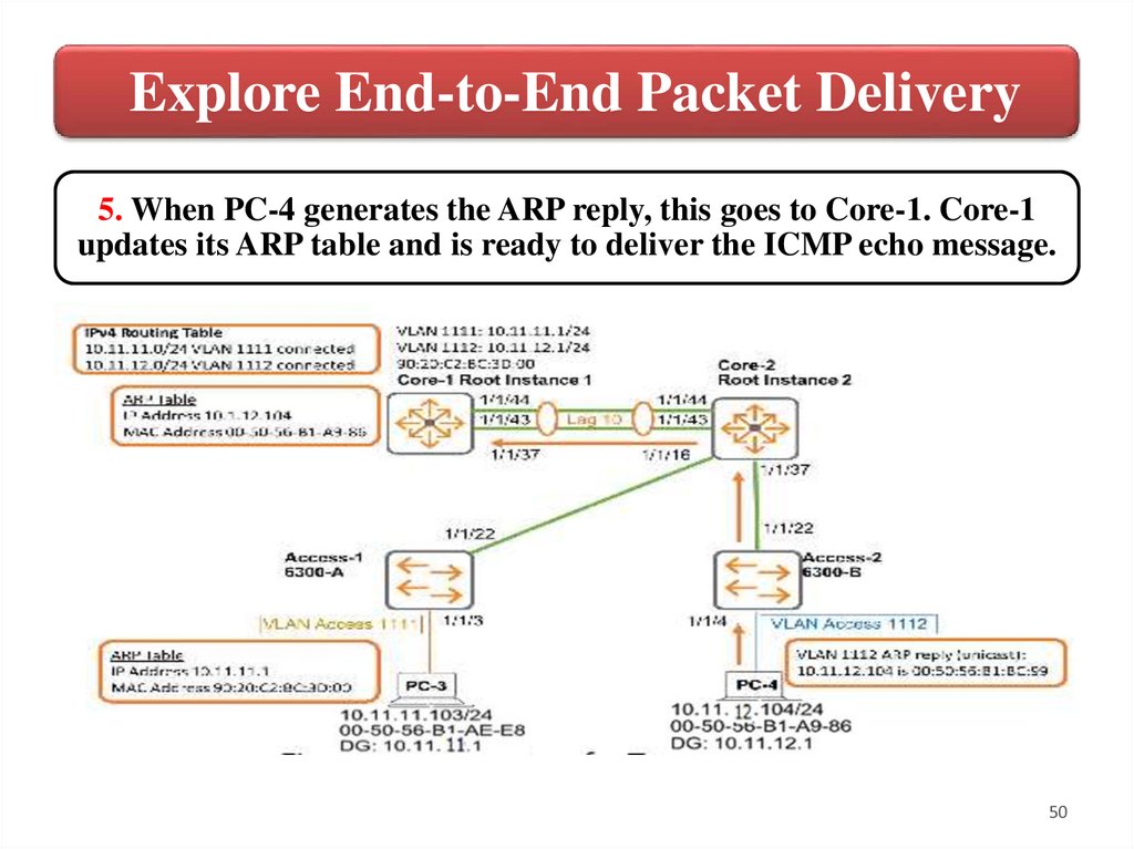
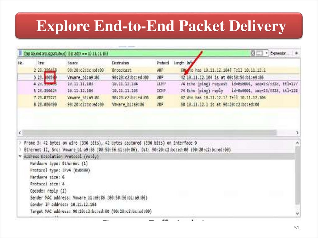
Explore End-to-End Packet Delivery5. When PC-4 generates the ARP reply, this goes to Core-1. Core-1
updates its ARP table and is ready to deliver the ICMP echo message.
50
51.
Explore End-to-End Packet Delivery51
52.
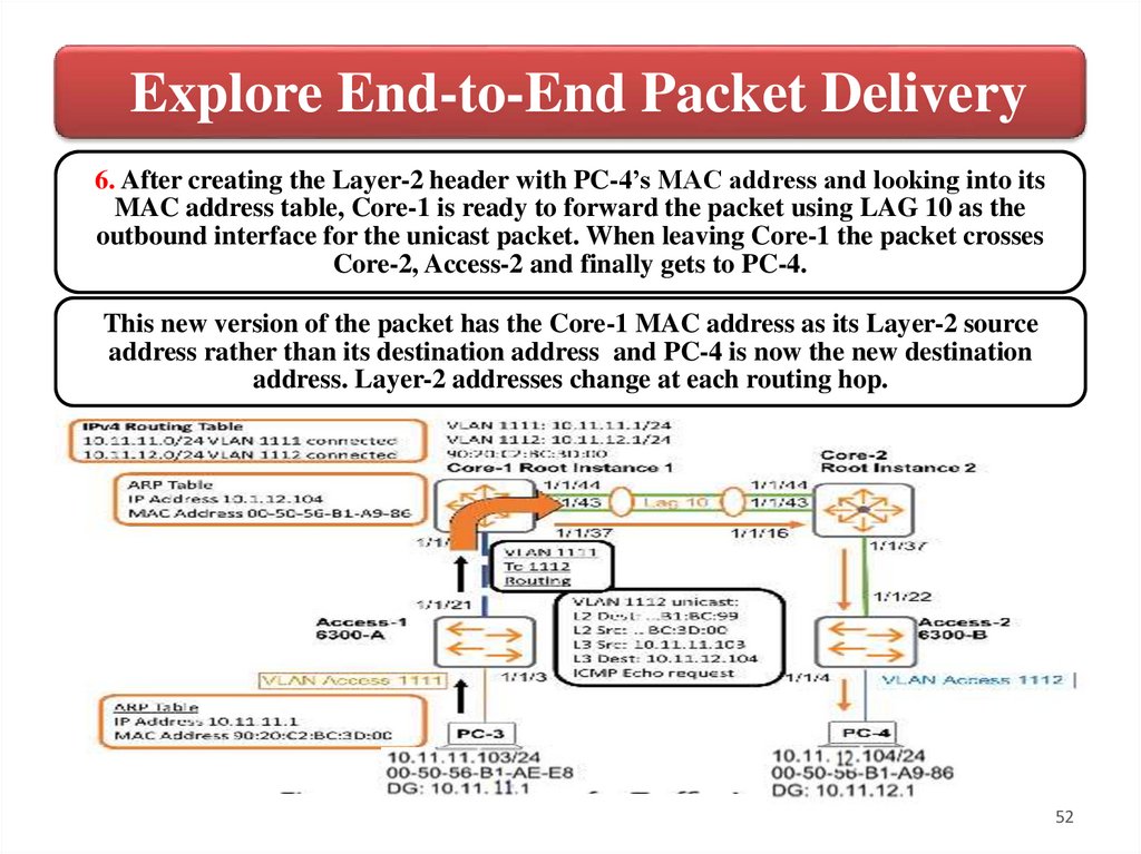
Explore End-to-End Packet Delivery6. After creating the Layer-2 header with PC-4’s MAC address and looking into its
MAC address table, Core-1 is ready to forward the packet using LAG 10 as the
outbound interface for the unicast packet. When leaving Core-1 the packet crosses
Core-2, Access-2 and finally gets to PC-4.
This new version of the packet has the Core-1 MAC address as its Layer-2 source
address rather than its destination address and PC-4 is now the new destination
address. Layer-2 addresses change at each routing hop.
52
53.
Explore End-to-End Packet Delivery53
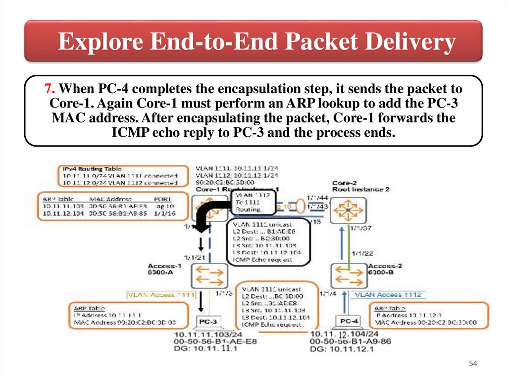
54.
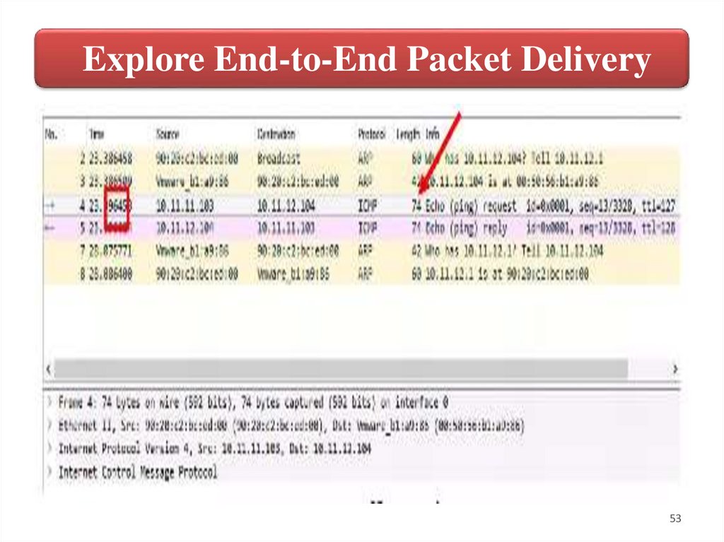
Explore End-to-End Packet Delivery7. When PC-4 completes the encapsulation step, it sends the packet to
Core-1. Again Core-1 must perform an ARP lookup to add the PC-3
MAC address. After encapsulating the packet, Core-1 forwards the
ICMP echo reply to PC-3 and the process ends.
54
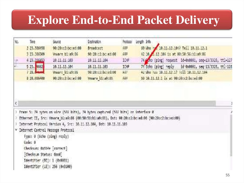
55.
Explore End-to-End Packet Delivery55
56.
Routing & VRRP4. Virtual Router Redundancy
Protocol (VRRP)
56
57.
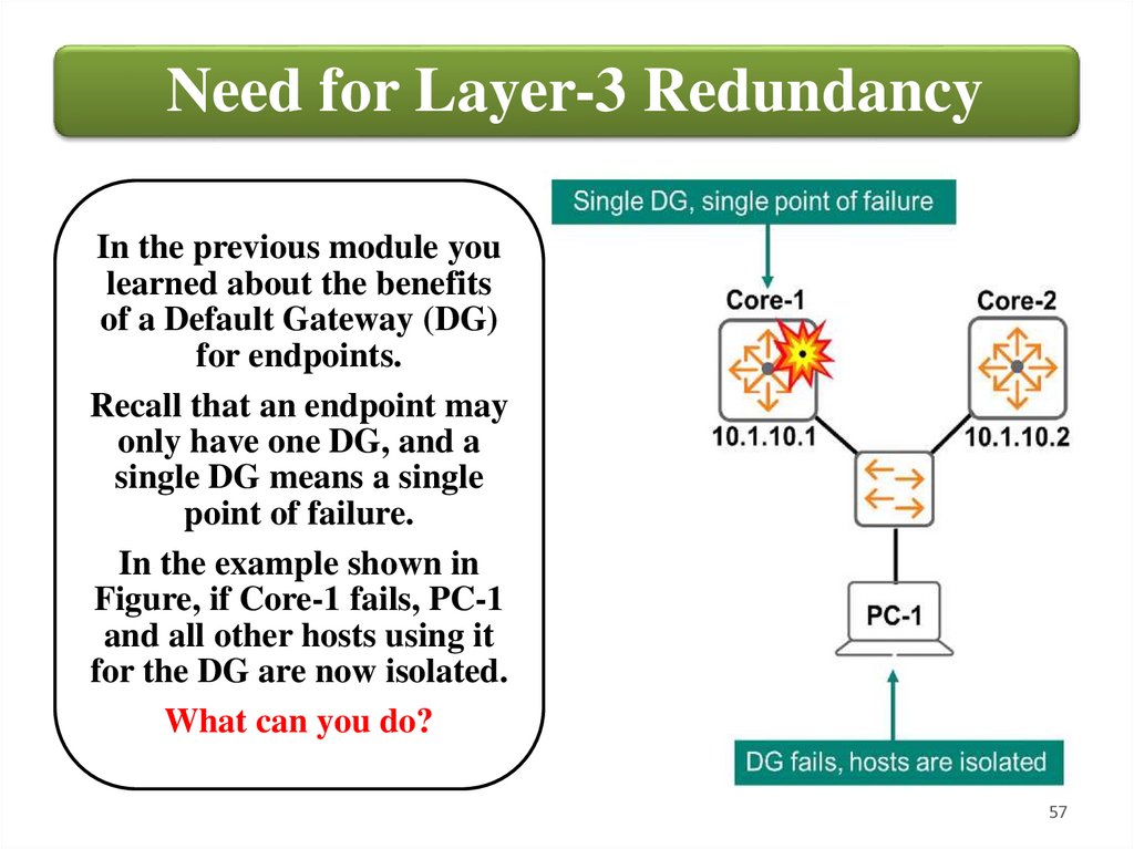
Need for Layer-3 RedundancyIn the previous module you
learned about the benefits
of a Default Gateway (DG)
for endpoints.
Recall that an endpoint may
only have one DG, and a
single DG means a single
point of failure.
In the example shown in
Figure, if Core-1 fails, PC-1
and all other hosts using it
for the DG are now isolated.
What can you do?
57
58.
Need for Layer-3 RedundancyYou could add another DG for redundancy. This seems like
an easy solution, but maybe not. Each endpoint’s DG is either
configured manually or obtained via DHCP. When Core-1
fails, you must either manually reconfigure each host with a
new DG or reconfigure the DHCP scope. Then ask all end
users to disconnect from the network and reconnect, power
cycle their PC, or teach them how to trigger a DHCP release
and renew action. (In a Windows command prompt for
example, use IPconfig/release, then IPconfig/renew).
However you do it, these methods are not very elegant or
scalable, and may be disruptive for end users.
There must be a better way, right?
58
59.
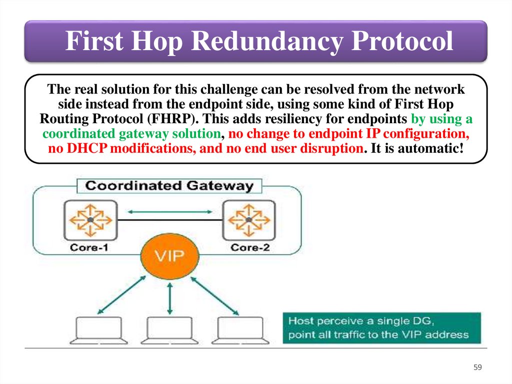
First Hop Redundancy ProtocolThe real solution for this challenge can be resolved from the network
side instead from the endpoint side, using some kind of First Hop
Routing Protocol (FHRP). This adds resiliency for endpoints by using a
coordinated gateway solution, no change to endpoint IP configuration,
no DHCP modifications, and no end user disruption. It is automatic!
59
60.
First Hop Redundancy ProtocolAn FHRP solution creates a single coordinated gateway from
two or more physical routers. The two physical routers present
themselves to endpoints as a single device, with a single Virtual
IP (VIP) address. This VIP acts as the endpoint’s DG.
Normally, the Primary routing device serves the DG role,
forwarding traffic for endpoints. The Secondary unit
monitors the Primary device state. If the Primary fails, the
Secondary device takes over. It takes on the Primary role and
VIP and forwards endpoint traffic. From the endpoint
perspective the Virtual IP address is always available. There is
no DG address change, and there is no disruption for end
users.
60
61.
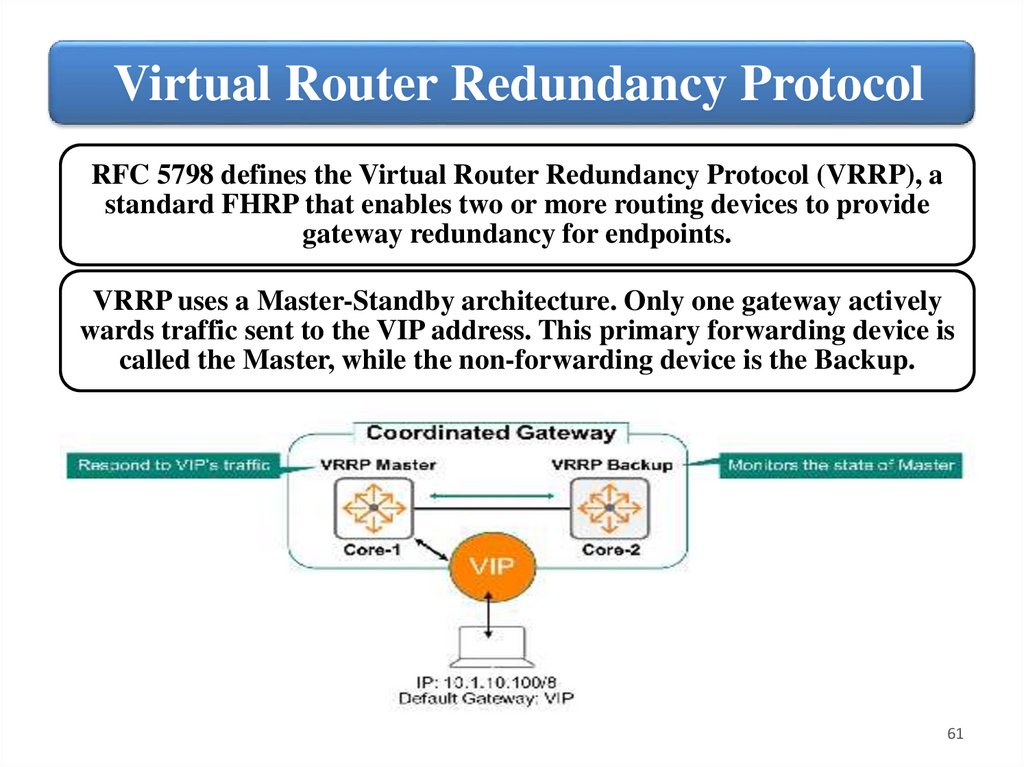
Virtual Router Redundancy ProtocolRFC 5798 defines the Virtual Router Redundancy Protocol (VRRP), a
standard FHRP that enables two or more routing devices to provide
gateway redundancy for endpoints.
VRRP uses a Master-Standby architecture. Only one gateway actively
wards traffic sent to the VIP address. This primary forwarding device is
called the Master, while the non-forwarding device is the Backup.
61
62.
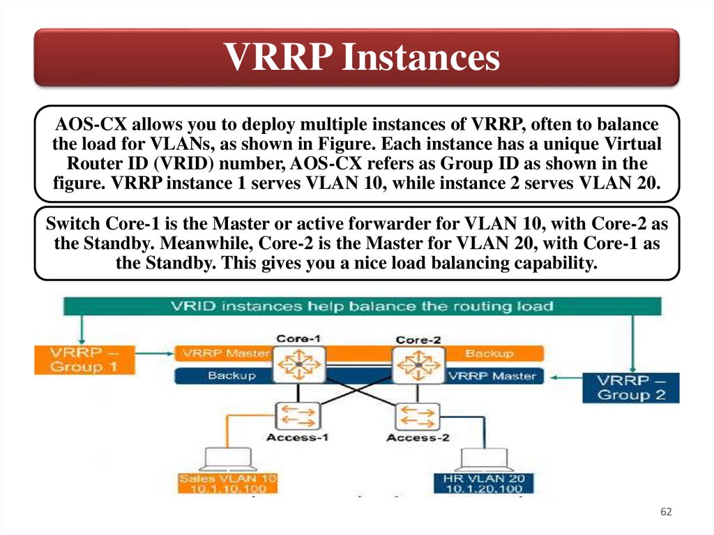
VRRP InstancesAOS-CX allows you to deploy multiple instances of VRRP, often to balance
the load for VLANs, as shown in Figure. Each instance has a unique Virtual
Router ID (VRID) number, AOS-CX refers as Group ID as shown in the
figure. VRRP instance 1 serves VLAN 10, while instance 2 serves VLAN 20.
Switch Core-1 is the Master or active forwarder for VLAN 10, with Core-2 as
the Standby. Meanwhile, Core-2 is the Master for VLAN 20, with Core-1 as
the Standby. This gives you a nice load balancing capability.
62
63.
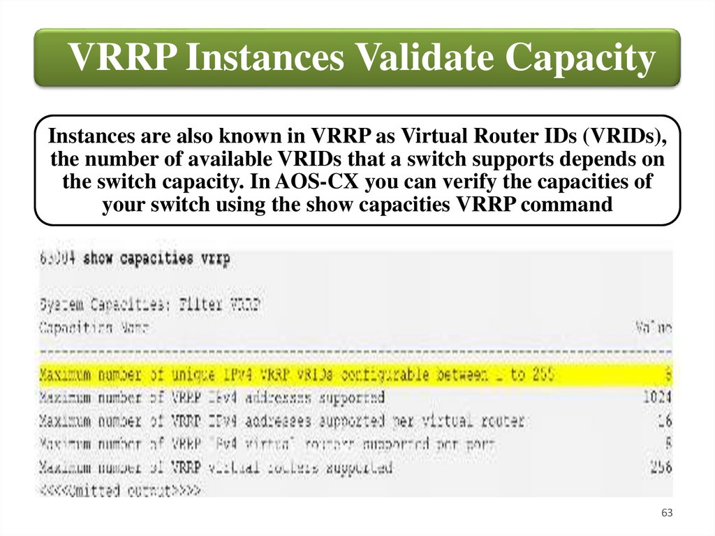
VRRP Instances Validate CapacityInstances are also known in VRRP as Virtual Router IDs (VRIDs),
the number of available VRIDs that a switch supports depends on
the switch capacity. In AOS-CX you can verify the capacities of
your switch using the show capacities VRRP command
63
64.
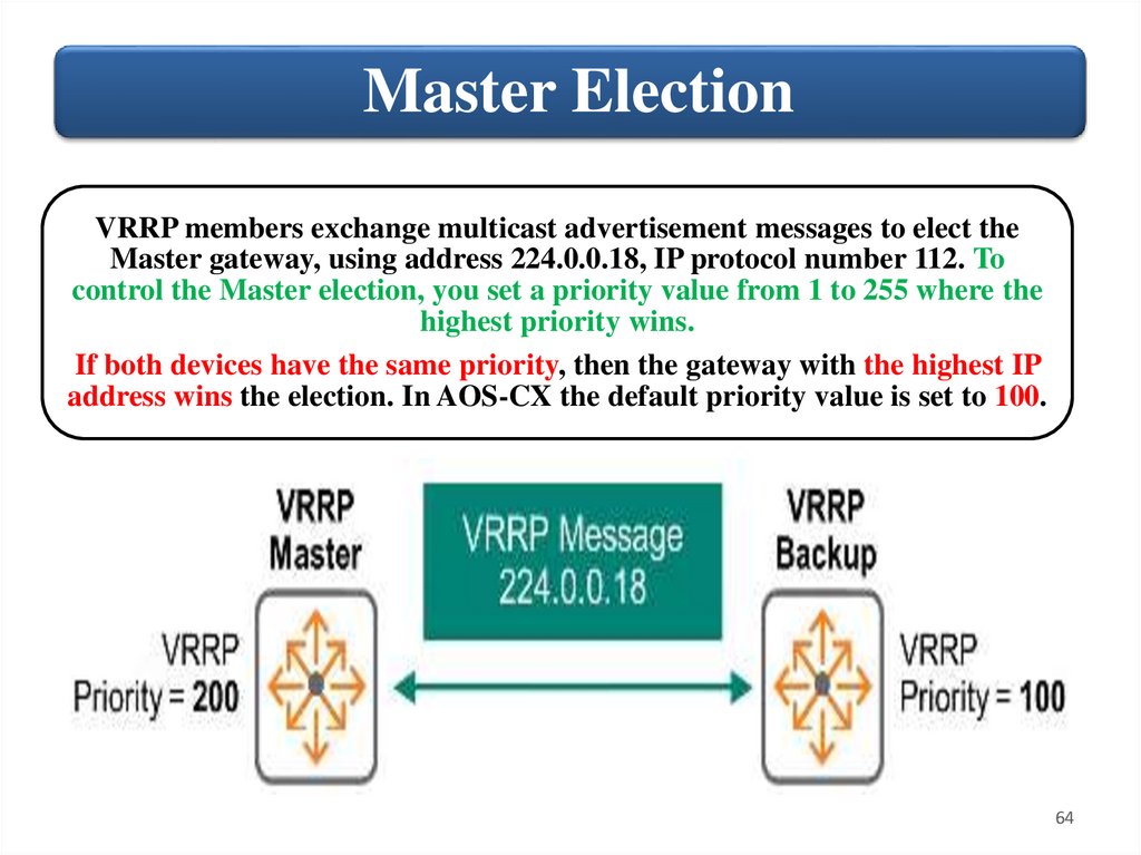
Master ElectionVRRP members exchange multicast advertisement messages to elect the
Master gateway, using address 224.0.0.18, IP protocol number 112. To
control the Master election, you set a priority value from 1 to 255 where the
highest priority wins.
If both devices have the same priority, then the gateway with the highest IP
address wins the election. In AOS-CX the default priority value is set to 100.
64
65.
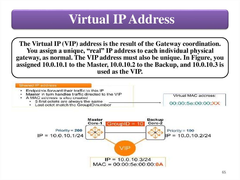
Virtual IP AddressThe Virtual IP (VIP) address is the result of the Gateway coordination.
You assign a unique, “real” IP address to each individual physical
gateway, as normal. The VIP address must also be unique. In Figure, you
assigned 10.0.10.1 to the Master, 10.0.10.2 to the Backup, and 10.0.10.3 is
used as the VIP.
65
66.
Virtual IP AddressEach VRRP instance has a unique VRRP address. 10.0.10.3 might be the
VIP address for Instance 10, used for VLAN 10. Meanwhile, 10.0.20.3
might be the VIP address for Instance 20, used for VLAN 20.
You must ensure that this VIP address is configured as the endpoint
Default Gateway. Thus, endpoints forward their traffic to the VIP. The
VRRP Master receives these packets and routes them. If the Master fails,
the Standby unit takes over. The devices do not learn about the router’s
physical IP addresses: 10.0.10.1 and 10.0.10.2 in the example.
A virtual MAC address (vMAC) is automatically assigned to the VIP. As
defined in the standard, this address shall be 00:00:5e:00:00:XX, where
XX = the VRID. In Figure above, the VRID = 10, and so the vMAC is
00:00:5e:00:00:0 (Hex A = 10 in decimal). Thus, when endpoints ARP for
their DG address of 10.0.10.3, they will learn the VMAC address, and
add it to their ARP table.
66
67.
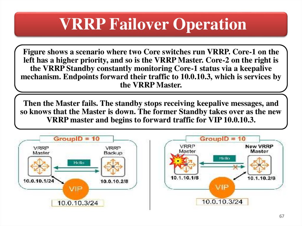
VRRP Failover OperationFigure shows a scenario where two Core switches run VRRP. Core-1 on the
left has a higher priority, and so is the VRRP Master. Core-2 on the right is
the VRRP Standby constantly monitoring Core-1 status via a keepalive
mechanism. Endpoints forward their traffic to 10.0.10.3, which is services by
the VRRP Master.
Then the Master fails. The standby stops receiving keepalive messages, and
so knows that the Master is down. The former Standby takes over as the new
VRRP master and begins to forward traffic for VIP 10.0.10.3.
67
68.
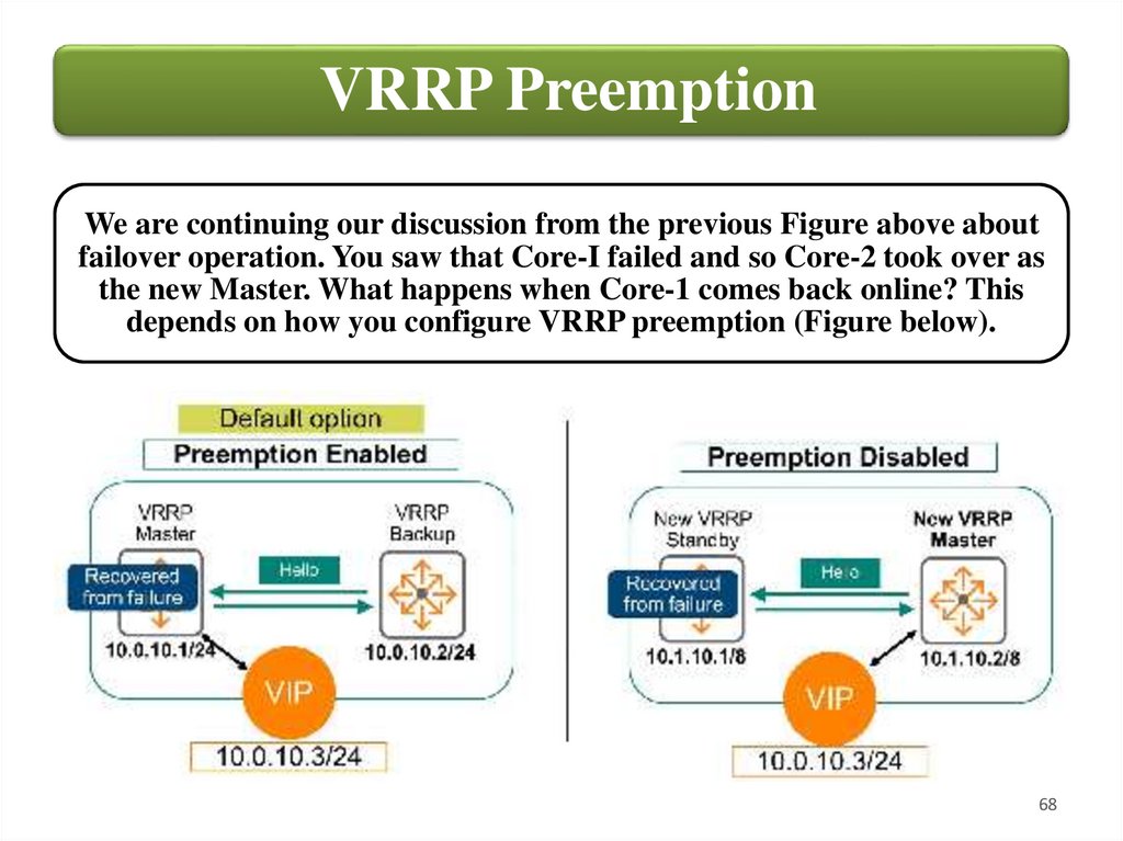
VRRP PreemptionWe are continuing our discussion from the previous Figure above about
failover operation. You saw that Core-I failed and so Core-2 took over as
the new Master. What happens when Core-1 comes back online? This
depends on how you configure VRRP preemption (Figure below).
68
69.
VRRP PreemptionIf Preemption is enabled, then Core-1 will reassume its original Master role
and Core-2 reverts to its Standby role. This is the AOS-CX default setting.
It is nice because you know that under normal operating conditions, when
all devices are up, the same router always acts as the Master. This can be
especially important if you are using multiple VRRP instances. If a Master
fails, the remaining device(s) will carry the load for all endpoints, while the
former Master, once again operational, remains unused.
If Preemption is disabled, then Core-1 will not resume its original Master
role. Core-2 remains the Master, and Core-1 takes on the Standby role. You
must manually disable preemption with the command no prempt. With
preemption disabled you lose the benefits described above. Some
administrators might choose to disable preemption if they are worried
about the (very brief) time lag that might occur during the preemption
process; while the routers switch back over to new operational states,
potentially during the middle of a busy day. Due to the high-performance
nature of AOS-CX devices, this is rarely a concern.
69
70.
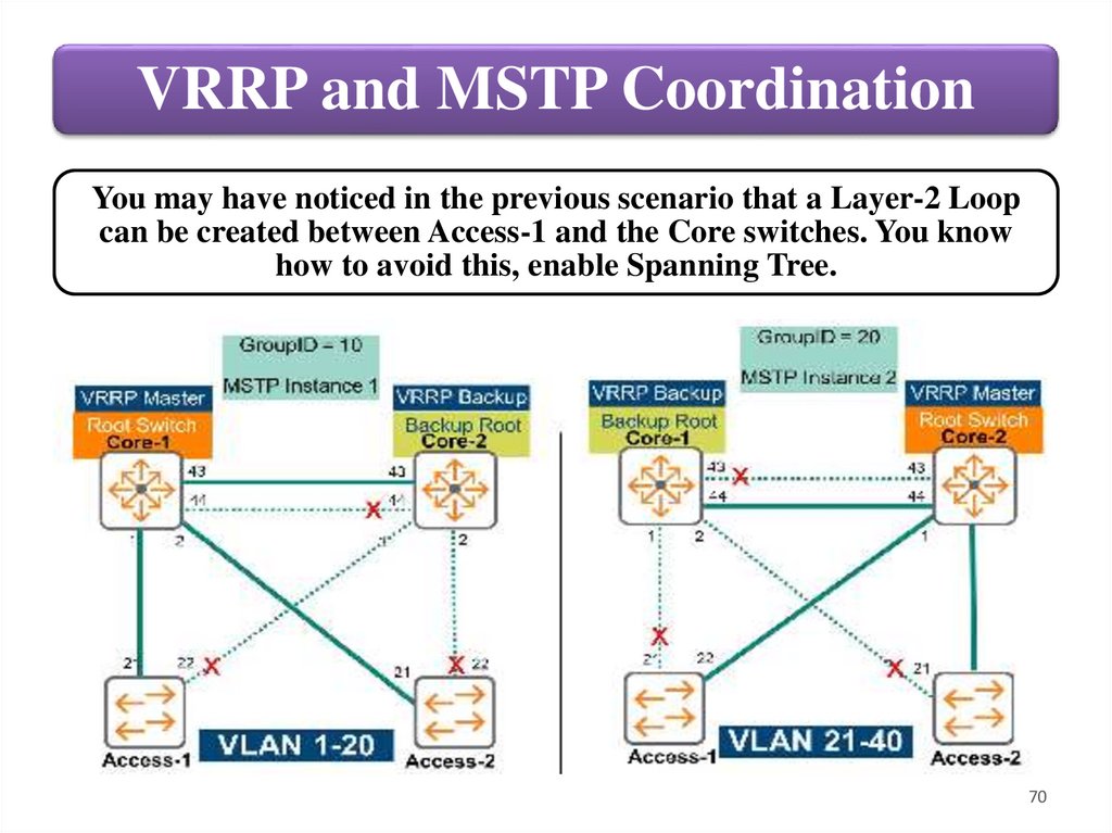
VRRP and MSTP CoordinationYou may have noticed in the previous scenario that a Layer-2 Loop
can be created between Access-1 and the Core switches. You know
how to avoid this, enable Spanning Tree.
70
71.
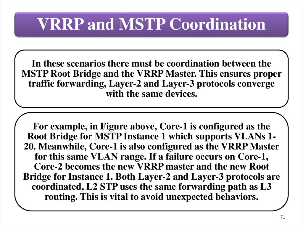
VRRP and MSTP CoordinationIn these scenarios there must be coordination between the
MSTP Root Bridge and the VRRP Master. This ensures proper
traffic forwarding, Layer-2 and Layer-3 protocols converge
with the same devices.
For example, in Figure above, Core-1 is configured as the
Root Bridge for MSTP Instance 1 which supports VLANs 120. Meanwhile, Core-1 is also configured as the VRRP Master
for this same VLAN range. If a failure occurs on Core-1,
Core-2 becomes the new VRRP master and the new Root
Bridge for Instance 1. Both Layer-2 and Layer-3 protocols are
coordinated, L2 STP uses the same forwarding path as L3
routing. This is vital to avoid unexpected behaviors.
71
72.
Routing & VRRP5. Deploying VRRP
72
73.
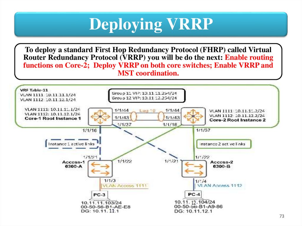
Deploying VRRPTo deploy a standard First Hop Redundancy Protocol (FHRP) called Virtual
Router Redundancy Protocol (VRRP) you will be do the next: Enable routing
functions on Core-2; Deploy VRRP on both core switches; Enable VRRP and
MST coordination.
73
74.
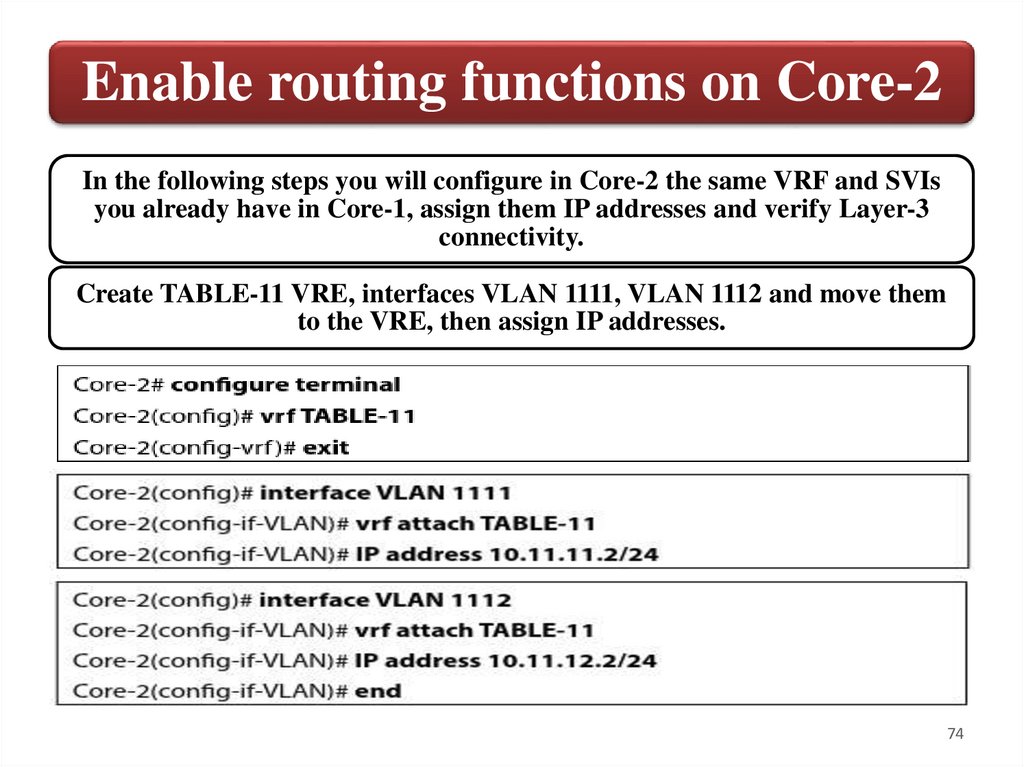
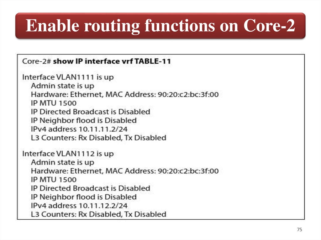
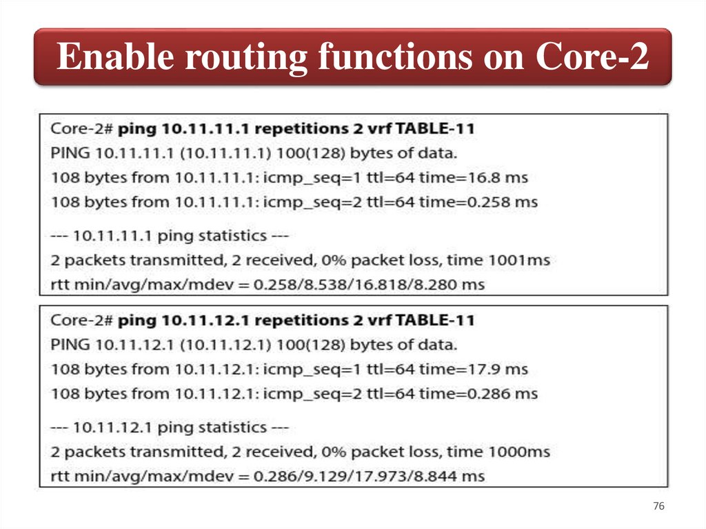
Enable routing functions on Core-2In the following steps you will configure in Core-2 the same VRF and SVIs
you already have in Core-1, assign them IP addresses and verify Layer-3
connectivity.
Create TABLE-11 VRE, interfaces VLAN 1111, VLAN 1112 and move them
to the VRE, then assign IP addresses.
74
75.
Enable routing functions on Core-275
76.
Enable routing functions on Core-276
77.
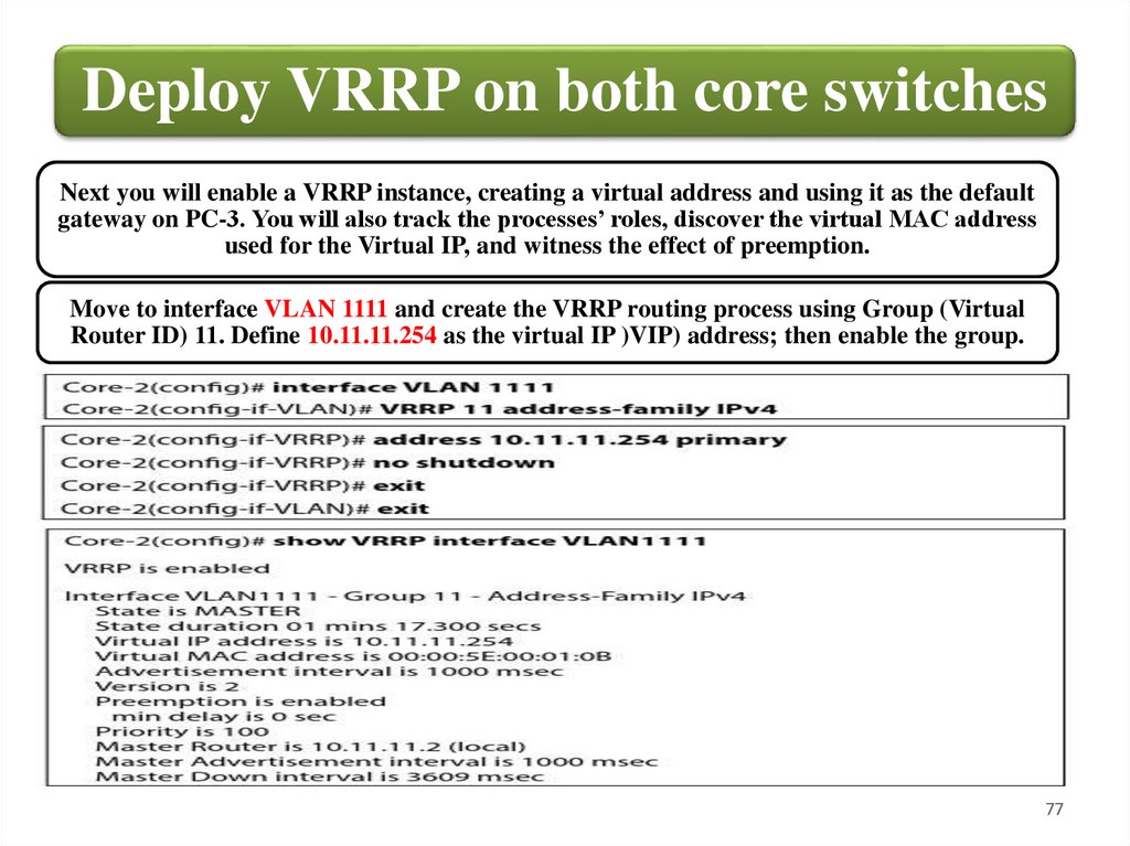
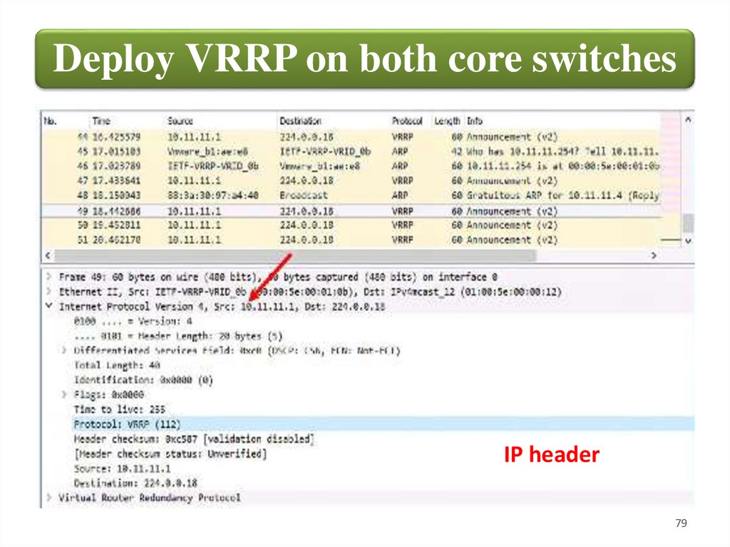
Deploy VRRP on both core switchesNext you will enable a VRRP instance, creating a virtual address and using it as the default
gateway on PC-3. You will also track the processes’ roles, discover the virtual MAC address
used for the Virtual IP, and witness the effect of preemption.
Move to interface VLAN 1111 and create the VRRP routing process using Group (Virtual
Router ID) 11. Define 10.11.11.254 as the virtual IP )VIP) address; then enable the group.
77
78.
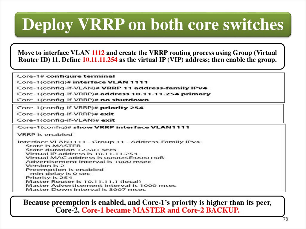
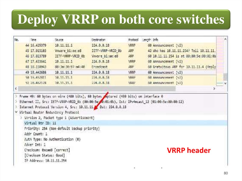
Deploy VRRP on both core switchesMove to interface VLAN 1112 and create the VRRP routing process using Group (Virtual
Router ID) 11. Define 10.11.11.254 as the virtual IP (VIP) address; then enable the group.
Because preemption is enabled, and Core-1’s priority is higher than its peer,
Core-2. Core-1 became MASTER and Core-2 BACKUP.
78
79.
Deploy VRRP on both core switchesIP header
79
80.
Deploy VRRP on both core switchesVRRP header
80
81.
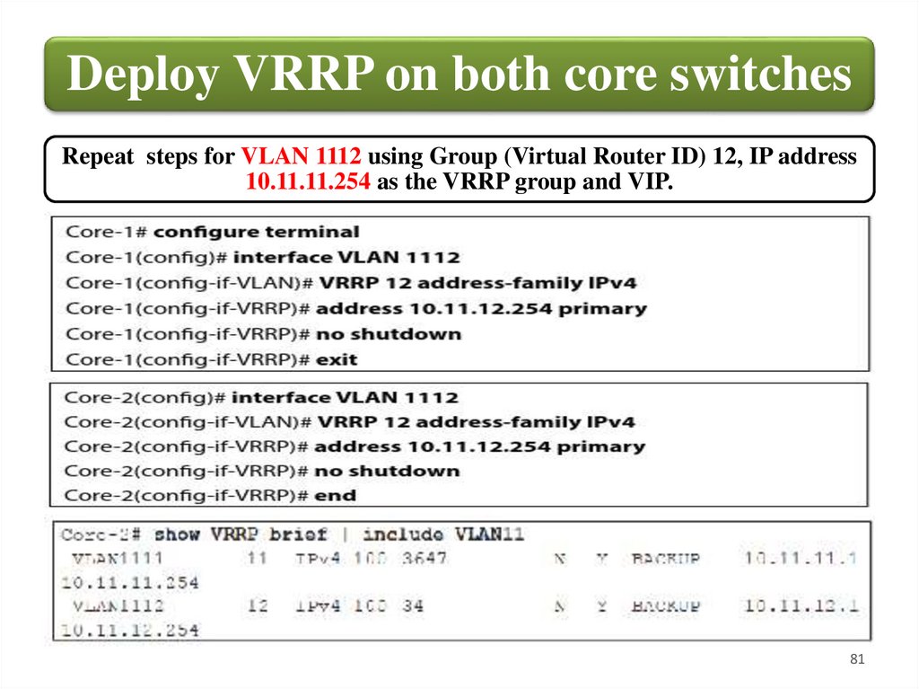
Deploy VRRP on both core switchesRepeat steps for VLAN 1112 using Group (Virtual Router ID) 12, IP address
10.11.11.254 as the VRRP group and VIP.
81
82.
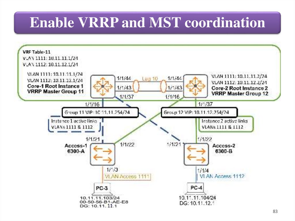
Enable VRRP and MST coordinationIn case of a priority tie the current MASTER remains MASTER. This makes
Core-1 control both VIPs under some situations e.g. a power outage when both
Core switches go down and Core-1 beats Core-2 during the boot process.
The problem with this is that Layer-3 load balancing is not guaranteed.
You currently have load sharing at Layer-2 by distributing the different MST
instances’ root bridges. A best practice is to coordinate both MST and VRRP as
seen in Figure below.
This way, under normal conditions Core-1 is both the root bridge for instance 1
(where VLAN 1111 belongs) and the VRRP Master for VLAN 1111's VIP.
Likewise, Core-2 is both the root bridge for instance 2 (where VLAN 1112
belongs) and the VRRP Master for VLAN 1112's VIP.
The ultimate result is when traffic must go out the local segment. As soon as
traffic hits either Core switch at Layer-2, that device is the gateway in charge of
routing the traffic at Layer-3.
82
83.
Enable VRRP and MST coordination83
84.
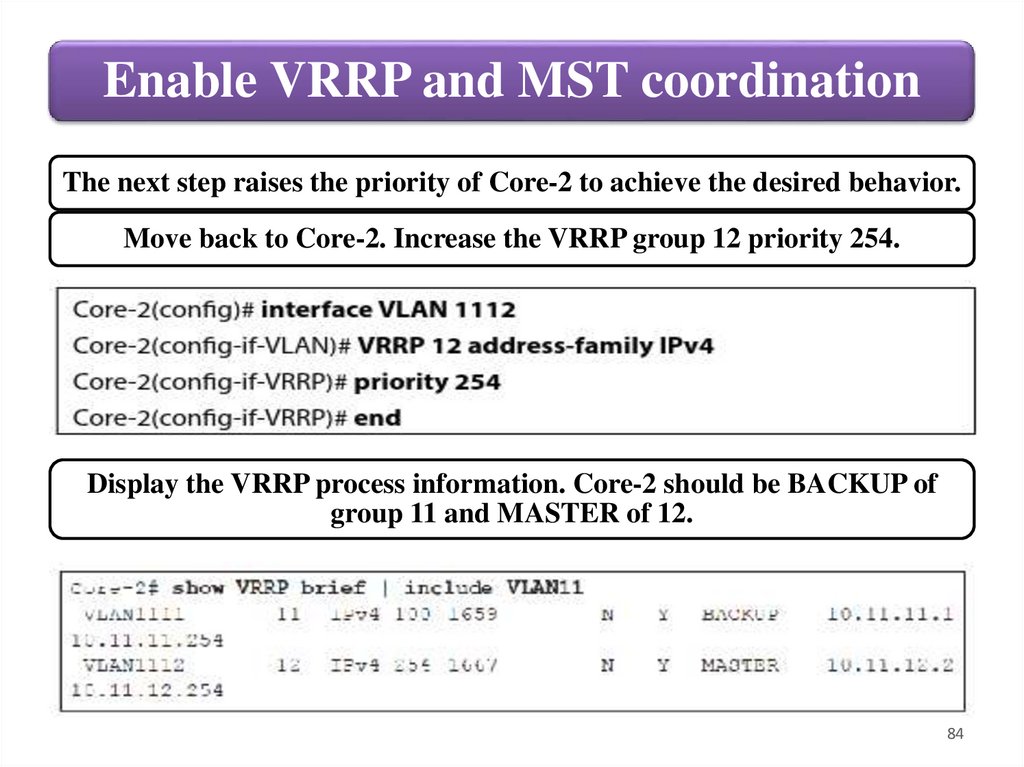
Enable VRRP and MST coordinationThe next step raises the priority of Core-2 to achieve the desired behavior.
Move back to Core-2. Increase the VRRP group 12 priority 254.
Display the VRRP process information. Core-2 should be BACKUP of
group 11 and MASTER of 12.
84