


 internet
Similar presentations:


Lecture 6 Routing
1.
Lecture 6Routing
1
2.
Objectives1. Explain routed network
fundamentals and justification.
2. List and describe the protocols used
for route management. Routing
Information Protocol (RIP)
3. Describe the routing protocol OSPF
(Open Shortest Path First).
2
3.
Routing1. Explain routed network fundamentals
and justification.
3
4.
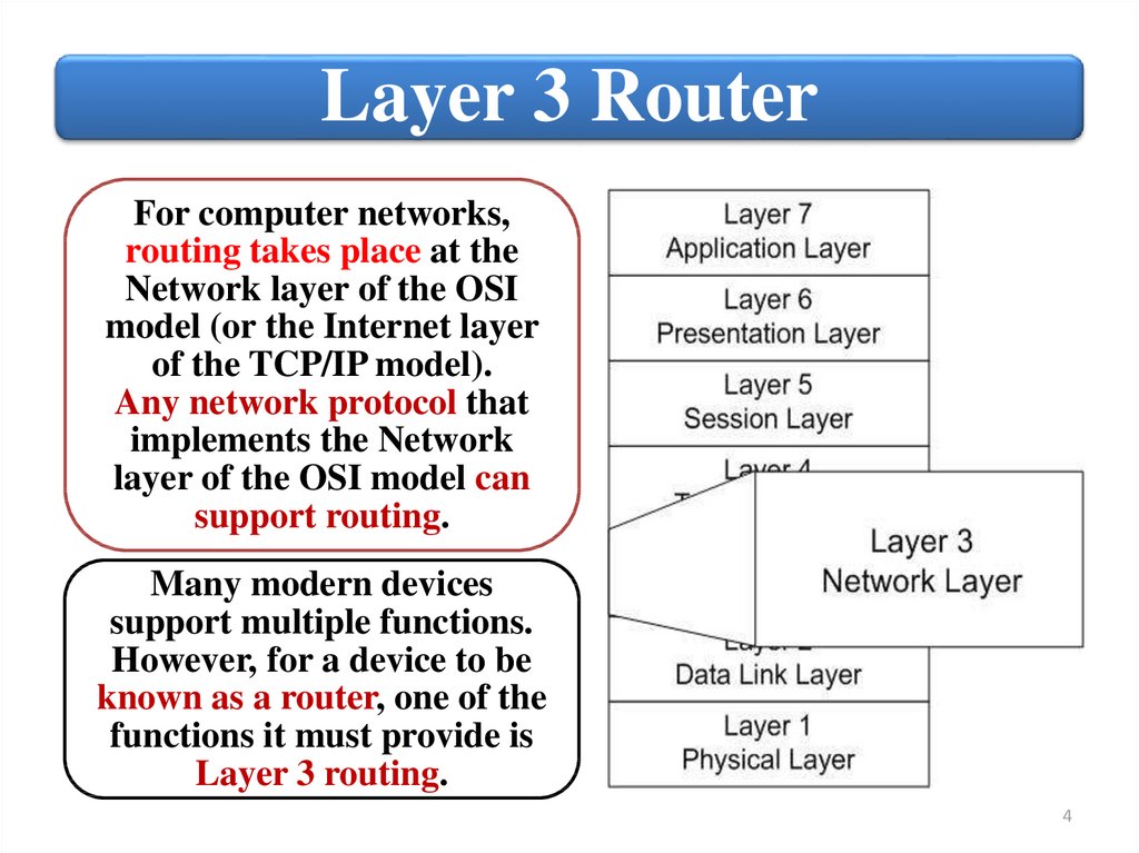
Layer 3 RouterFor computer networks,
routing takes place at the
Network layer of the OSI
model (or the Internet layer
of the TCP/IP model).
Any network protocol that
implements the Network
layer of the OSI model can
support routing.
Many modern devices
support multiple functions.
However, for a device to be
known as a router, one of the
functions it must provide is
Layer 3 routing.
4
5.
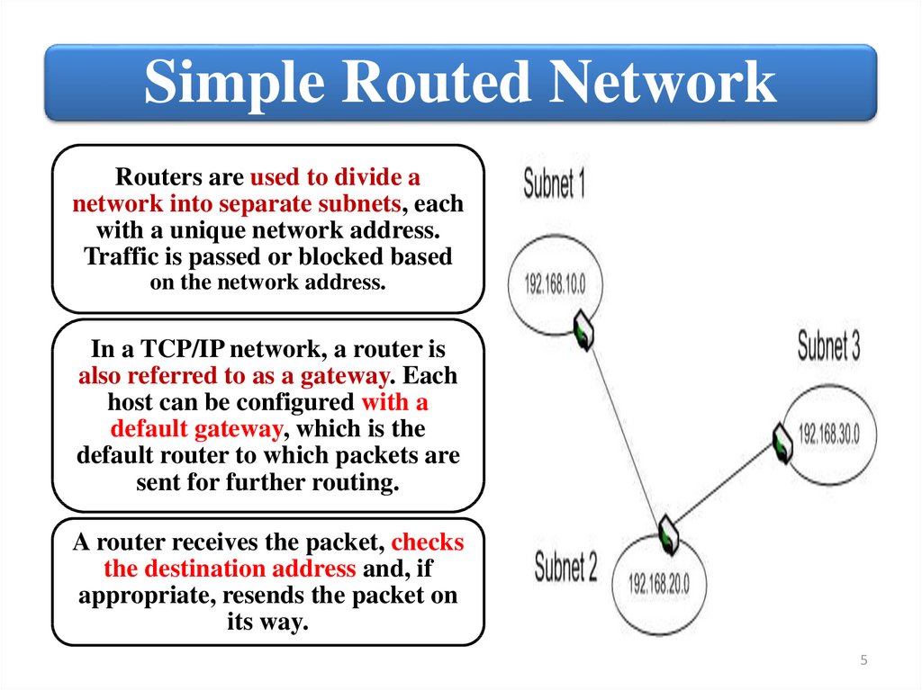
Simple Routed NetworkRouters are used to divide a
network into separate subnets, each
with a unique network address.
Traffic is passed or blocked based
on the network address.
In a TCP/IP network, a router is
also referred to as a gateway. Each
host can be configured with a
default gateway, which is the
default router to which packets are
sent for further routing.
A router receives the packet, checks
the destination address and, if
appropriate, resends the packet on
its way.
5
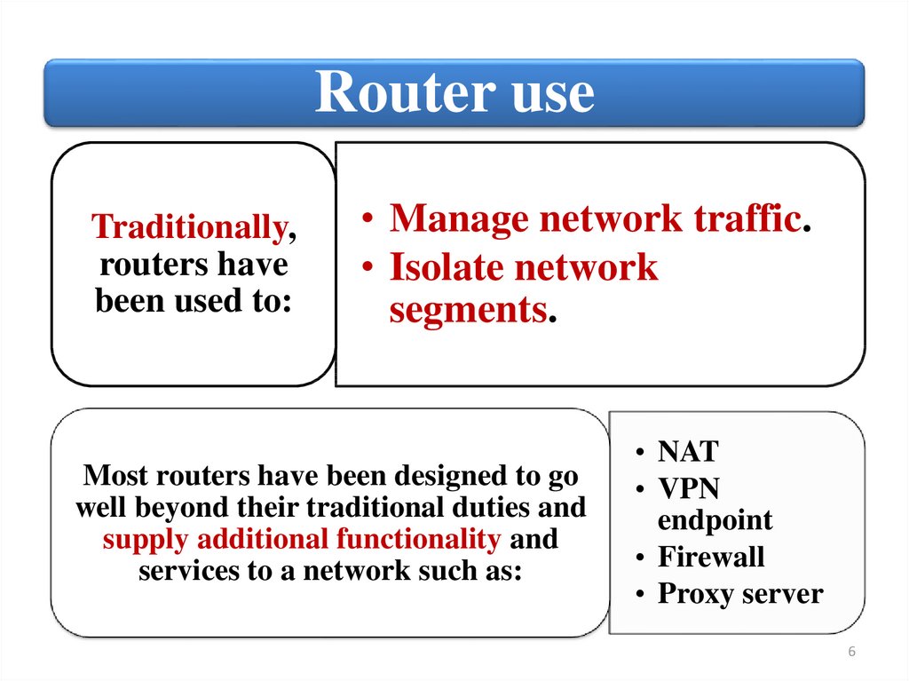
6.
Router useTraditionally,
routers have
been used to:
• Manage network traffic.
• Isolate network
segments.
Most routers have been designed to go
well beyond their traditional duties and
supply additional functionality and
services to a network such as:
• NAT
• VPN
endpoint
• Firewall
• Proxy server
6
7.
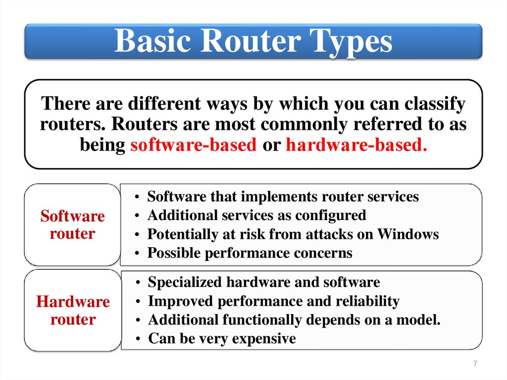
Basic Router TypesThere are different ways by which you can classify
routers. Routers are most commonly referred to as
being software‐based or hardware‐based.
Software
router
Software that implements router services
Additional services as configured
Potentially at risk from attacks on Windows
Possible performance concerns
Hardware
router
Specialized hardware and software
Improved performance and reliability
Additional functionally depends on a model.
Can be very expensive
7
8.
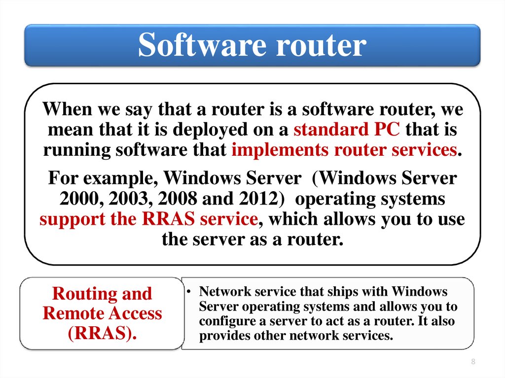
Software routerWhen we say that a router is a software router, we
mean that it is deployed on a standard PC that is
running software that implements router services.
For example, Windows Server (Windows Server
2000, 2003, 2008 and 2012) operating systems
support the RRAS service, which allows you to use
the server as a router.
Routing and
Remote Access
(RRAS).
• Network service that ships with Windows
Server operating systems and allows you to
configure a server to act as a router. It also
provides other network services.
8
9.
Routing and Remote Access (RRAS)With Routing and Remote Access (RRAS), a computer
running Windows Server 2008 can function as a network
router, which routes IP packets between networks.
9
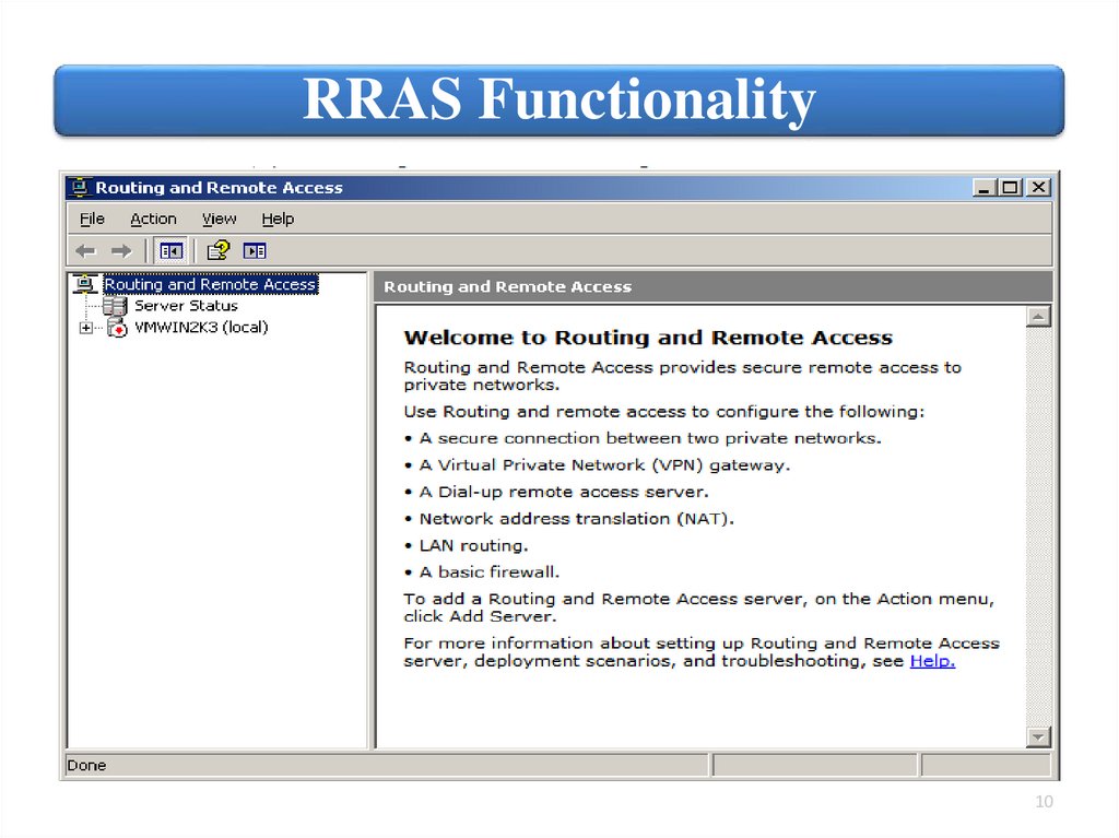
10.
RRAS Functionality10
11.
Hardware routerA hardware router (also called a dedicated
router). It is a specialized computer with
hardware designed and optimized
specifically for routing network traffic.
Routing functionality is still provided
through software, but the software is
dedicated to a specific purpose.
Dedicated
router.
• Network device deployed
specifically as a router.
11
12.
HP Hardware routerHP offers a wide range of router products targeted at
customers from SMB to very large enterprises. The software
is maintained in nonvolatile memory (firmware) rather than
on a hard disk or other magnetic media.
HP Networking Routers:
HP FlexBranch
solution
HP Branch solution
• MSR20, MSR30, MSR50,
• MSR1000, MSR2000, MSR3000,
MSR4000, MSR900, MSR93x
HP Campus solution
• HSR6600 Router Series, 6600 Router Series
HP Data Center
solution
• HSR6800 Router Series, 8800 Router Series
12
13.
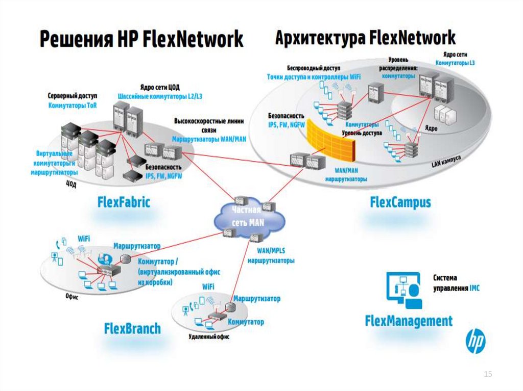
HP MSR20 Series RouterThe HP MSR20 (30,50) router series is a
component of the HP FlexBranch solution,
which is part of the
HP FlexNetwork architecture.
13
14.
HP FlexNetwork architecture14
15.
1516.
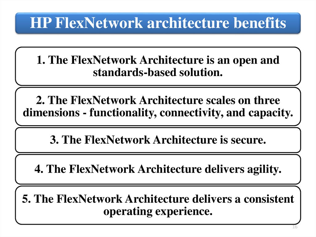
HP FlexNetwork architecture benefits1. The FlexNetwork Architecture is an open and
standards-based solution.
2. The FlexNetwork Architecture scales on three
dimensions - functionality, connectivity, and capacity.
3. The FlexNetwork Architecture is secure.
4. The FlexNetwork Architecture delivers agility.
5. The FlexNetwork Architecture delivers a consistent
operating experience.
16
17.
Routing2. List and describe the protocols used for
route management. Routing Information
Protocol (RIP)
17
18.
RoutingRouting is, quite simply, the process of
forwarding a packet from its source to
its destination through a routed
network.
The sending host does not need to
know anything about the destination
host’s physical location, just its
network and host addresses.
18
19.
Route InformationRouters maintain information
about routes in an RIB or
routing table.
A routing table is basically a
table containing known subnets
and which of the routers’
interfaces should be used for
forwarding a packet destined
for a particular subnet.
• Table maintained in a router
Routing
that contains information
Information
about routes and used to
Base (RIB).
direct packets.
19
20.
Routing tableAt minimum,
a routing
table includes
the following:
• Destination network ID (IP
address and subnet mask)
• Cost (weighting used to
determine best router)
• Next hop (next router in the
path to the destination)
You will typically also have an entry with the IP address of
the network interface through which the packet should be
routed. If the destination is not listed in the routing table,
the packet is forwarded to the router’s default route (called
default gateway).
20
21.
Unicast Routing ExampleA host on Subnet 1 generates a
packet with a destination address
of 192.168.40.115 on Subnet 4.
Because there are multiple paths,
the router must make a decision
about the best route to take.
How is a decision made about the best
route to take to the destination?
It is simply done by the intervening
routers and dynamic routing protocols
between the source and destination.
21
22.
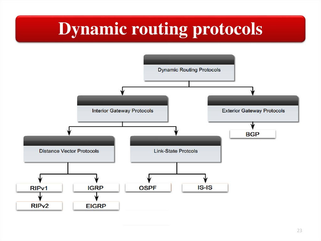
Routing ProtocolsThere are two basic types of dynamic routing
protocols. A dynamic routing protocol supports
either interior gateway routing or exterior
gateway routing.
Interior Gateway
Protocols (IGP)
• Routing protocols designed to support
routers deployed in LAN and WAN
environments.
Exterior Gateway
Protocols (EGP)
• Routing protocols used to support
Internet routers.
Our discussion focuses on the routing protocols that
support interior gateway protocol.
22
23.
Dynamic routing protocols23
24.
Interior Gateway Protocols (IGP)RIP
• Routing Information Protocol. Is one of the oldest distancevector routing protocols which employ the hop count as a
routing metric. RIP prevents routing loops by implementing a
limit on the number of hops allowed in a path from source to
destination.
OSPF
• Open Shortest Path First. Is most often used to dynamically
manage network routes in large enterprise network. OSPF use
link-state algorithms to send routing information to all nodes in
an internetwork by calculating the shortest path to each node
based on a topology of the Internet constructed by each node.
IGRP
• Interior Gateway Routing Protocol. Is a distance vector interior
routing protocol (IGP) developed by Cisco. It is used by routers
to exchange routing data within an autonomous system.
IS-IS
• Intermediate System to Intermediate System. Is a routing
protocol designed to move information efficiently within a
computer network, a group of physically connected computers or
similar devices. It accomplishes this by determining the best
route for datagrams through a packet-switched network.
24
25.
Routing Information Protocol(RIP)
25
26.
Routing Information Protocol (RIP)RIP is an interior gateway protocol (IGP), which means that
it performs routing within a single autonomous system.
The Routing Information Protocol (RIP) is a distance-vector
protocol that uses hop count as its metric.
RIP only uses hop count to determine the best route to a
remote network, RIP has a maximum hop count of 15, 16 is
deemed unreachable.
RIP is susceptible to all the problems normally associated
with distance vector routing protocols. It is slow to converge
and forces routers to learn network information only from
neighbors.
26
27.
Routing UpdatesRIP sends its complete routing table out to all active interfaces at regular
intervals (every 30 seconds) and when the network topology changes. When a
router receives a routing update that includes changes to an entry, it updates its
routing table to reflect the new route.
The metric value for the path is increased by one. RIP implement a limit on the
number of hops allowed in a path from the source to a destination (15 hops). If a
router receives a routing update that contains a new or changed entry, and if
increasing the metric value by one causes the metric to be infinity (that is, 16),
the network destination is considered unreachable.
After updating its routing table, the router immediately begins transmitting
routing updates to inform other network routers of the change.
27
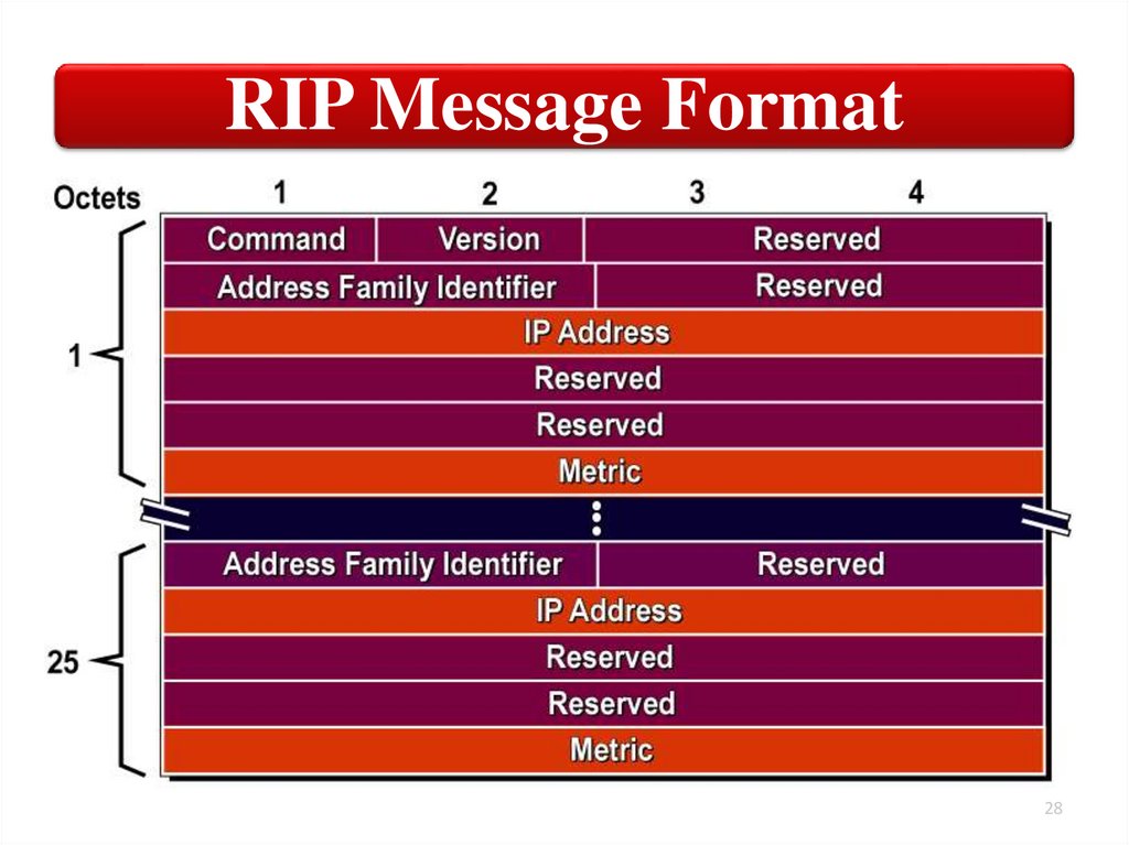
28.
RIP Message Format28
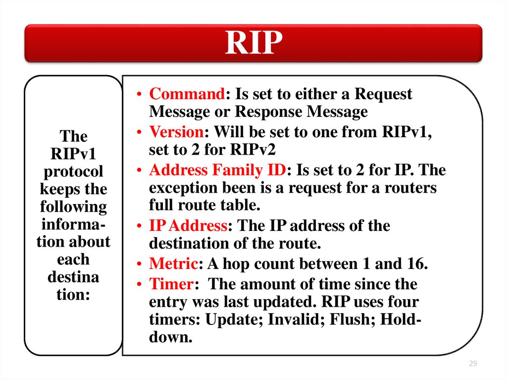
29.
RIPThe
RIPv1
protocol
keeps the
following
information about
each
destina
tion:
• Command: Is set to either a Request
Message or Response Message
• Version: Will be set to one from RIPv1,
set to 2 for RIPv2
• Address Family ID: Is set to 2 for IP. The
exception been is a request for a routers
full route table.
• IP Address: The IP address of the
destination of the route.
• Metric: A hop count between 1 and 16.
• Timer: The amount of time since the
entry was last updated. RIP uses four
timers: Update; Invalid; Flush; Holddown.
29
30.
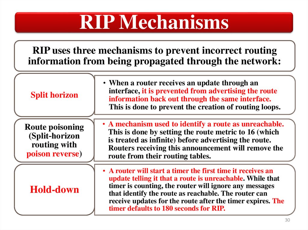
RIP MechanismsRIP uses three mechanisms to prevent incorrect routing
information from being propagated through the network:
Split horizon
• When a router receives an update through an
interface, it is prevented from advertising the route
information back out through the same interface.
This is done to prevent the creation of routing loops.
Route poisoning
(Split‐horizon
routing with
poison reverse)
• A mechanism used to identify a route as unreachable.
This is done by setting the route metric to 16 (which
is treated as infinite) before advertising the route.
Routers receiving this announcement will remove the
route from their routing tables.
Hold-down
• A router will start a timer the first time it receives an
update telling it that a route is unreachable. While that
timer is counting, the router will ignore any messages
that identify the route as reachable. The router can
receive updates for the route after the timer expires. The
timer defaults to 180 seconds for RIP.
30
31.
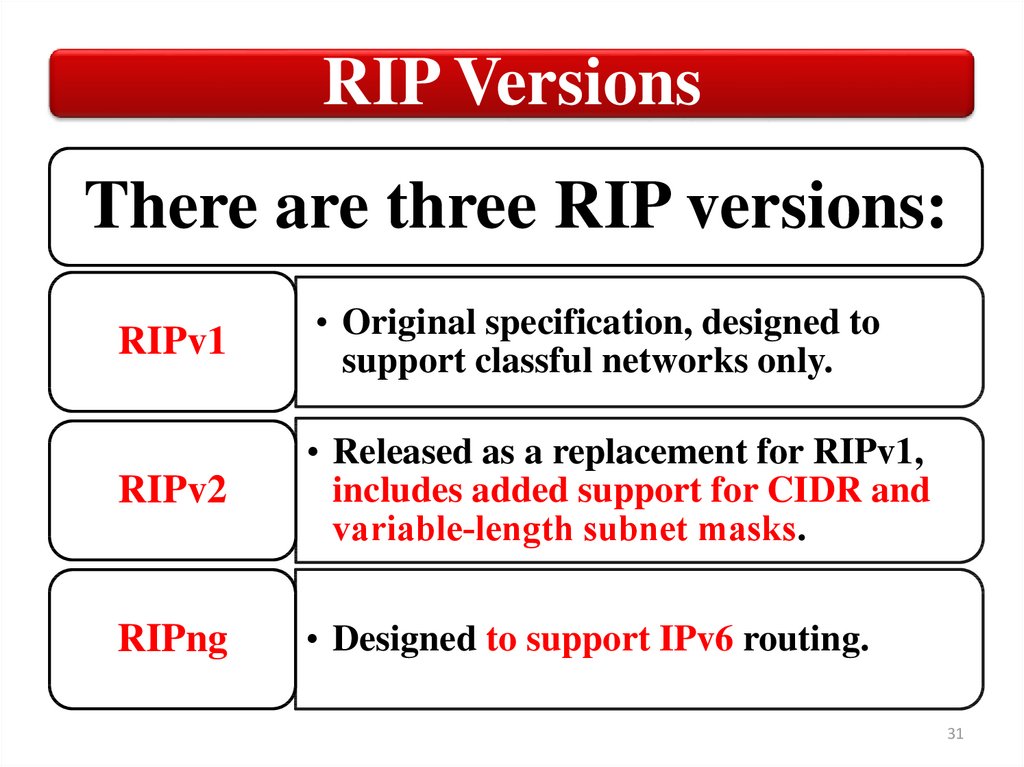
RIP VersionsThere are three RIP versions:
RIPv1
• Original specification, designed to
support classful networks only.
RIPv2
• Released as a replacement for RIPv1,
includes added support for CIDR and
variable‐length subnet masks.
RIPng
• Designed to support IPv6 routing.
31
32.
RIPv2The
similarities
between
the RIPv1
and RIPv2
are as
follows:
• Use of the triggered updates while
there is the change in a topology
for the faster convergence.
• Use of the split horizon with
poison reverse or split horizon to
prevent the routing loops.
• Use of the timers and hold-down
to prevent the routing loops.
• The maximum hop count of 15,
with 16 hop count signifying as an
unreachable.
32
33.
RIPv2The
enhanced
features
in RIPv2
are such
as:
• RIPv2 added support for
variable‐length subnet masks and for
CIDR.
• Next hop addresses are included in a
routing update.
• Authentication option available, allows
packets to be authenticated via either
an insecure plain text password or a
secure MD5 hash based authentication.
• Use of the multicast address in the
sending updates. RIPv2 sends updates
through multicast transmissions to
address 224.0.0.9, reaching all adjacent
routers.
33
34.
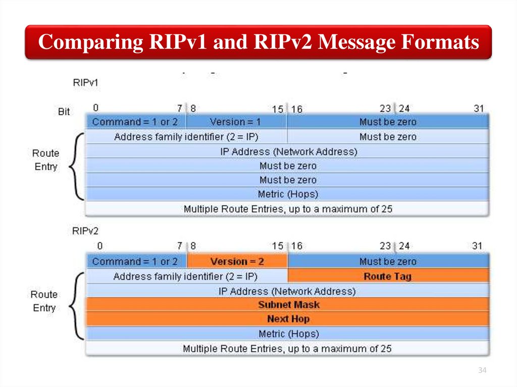
Comparing RIPv1 and RIPv2 Message Formats34
35.
RIPngRIP next generation (RIPng) was developed as an
extension to RIPv2 and is not fully compatible with
routers that support RIPv1 only.
RIPng is an interior gateway protocol (IGP) that
uses a distance vector algorithm to determine the
best route to a destination, using the hop count as
the metric.
RIPng is an entirely separate routing protocol that
exchanges routing information used to compute
routes and is intended for IPv6-based networks.
35
36.
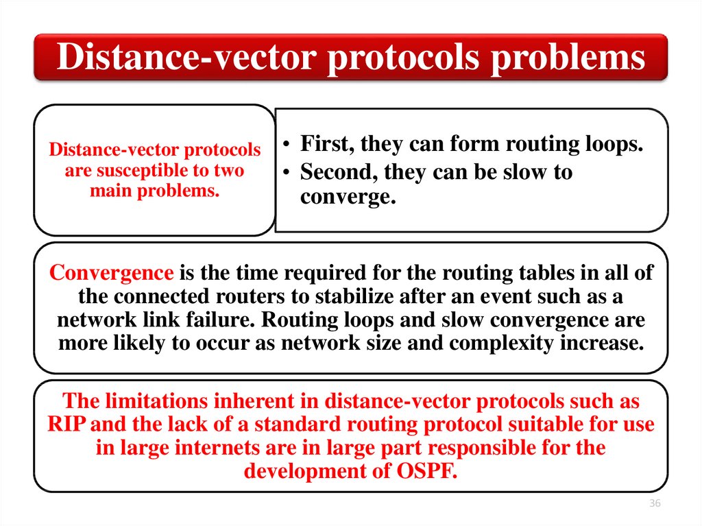
Distance-vector protocols problemsDistance-vector protocols
are susceptible to two
main problems.
• First, they can form routing loops.
• Second, they can be slow to
converge.
Convergence is the time required for the routing tables in all of
the connected routers to stabilize after an event such as a
network link failure. Routing loops and slow convergence are
more likely to occur as network size and complexity increase.
The limitations inherent in distance-vector protocols such as
RIP and the lack of a standard routing protocol suitable for use
in large internets are in large part responsible for the
development of OSPF.
36
37.
Routing3. Describe the routing protocol OSPF
(Open Shortest Path First)
37
38.
OSPF definitionOSPF is an open-standard routing protocol that
converges quickly. OSPF is most often used to
dynamically manage network routes in large
enterprise network.
OSPF is a link-state routing protocol and uses
Dijkstra’s Shortest Path First (SPF) algorithm to
determine its best path to each network.
Link state routing protocols learn more information
on the structure of the network than other routing
protocols and thus can make more informed routing
decisions.
38
39.
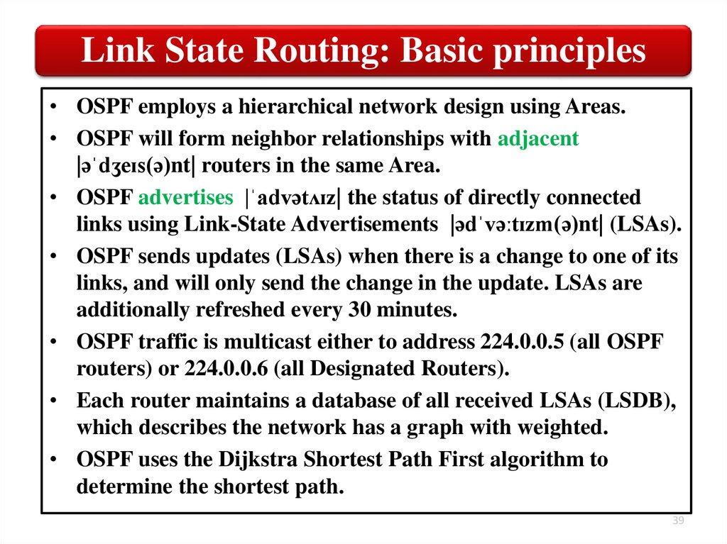
Link State Routing: Basic principles• OSPF employs a hierarchical network design using Areas.
• OSPF will form neighbor relationships with adjacent
|əˈdʒeɪs(ə)nt| routers in the same Area.
• OSPF advertises |ˈadvətʌɪz| the status of directly connected
links using Link-State Advertisements |ədˈvəːtɪzm(ə)nt| (LSAs).
• OSPF sends updates (LSAs) when there is a change to one of its
links, and will only send the change in the update. LSAs are
additionally refreshed every 30 minutes.
• OSPF traffic is multicast either to address 224.0.0.5 (all OSPF
routers) or 224.0.0.6 (all Designated Routers).
• Each router maintains a database of all received LSAs (LSDB),
which describes the network has a graph with weighted.
• OSPF uses the Dijkstra Shortest Path First algorithm to
determine the shortest path.
39
40.
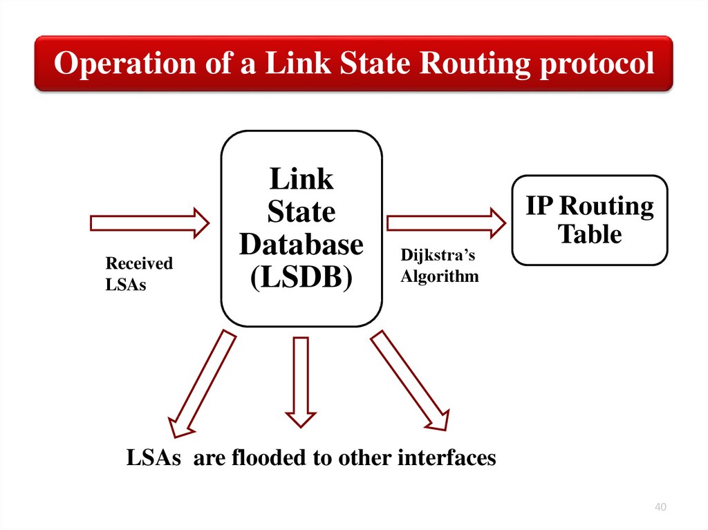
Operation of a Link State Routing protocolReceived
LSAs
Link
State
Database
(LSDB)
Dijkstra’s
Algorithm
IP Routing
Table
LSAs are flooded to other interfaces
40
41.
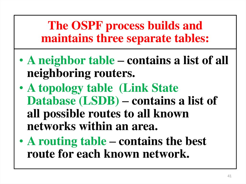
The OSPF process builds andmaintains three separate tables:
• A neighbor table – contains a list of all
neighboring routers.
• A topology table (Link State
Database (LSDB) – contains a list of
all possible routes to all known
networks within an area.
• A routing table – contains the best
route for each known network.
41
42.
Operation of a Link State Routing protocol42
43.
OSPF uses five types of routing protocol packets44.
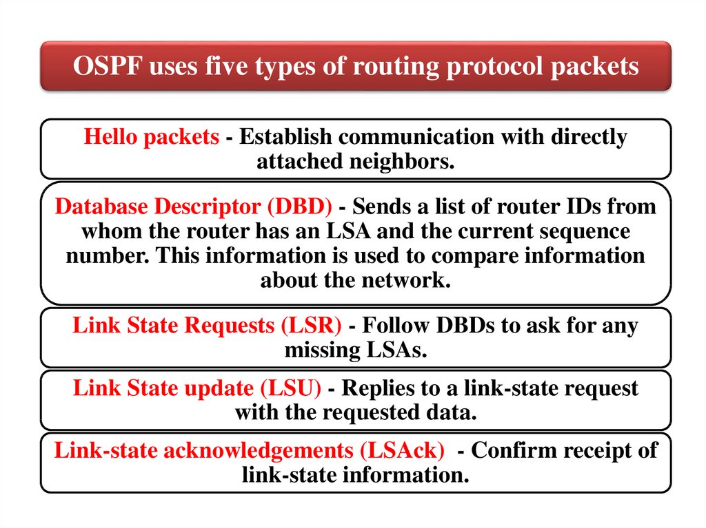
OSPF uses five types of routing protocol packetsHello packets - Establish communication with directly
attached neighbors.
Database Descriptor (DBD) - Sends a list of router IDs from
whom the router has an LSA and the current sequence
number. This information is used to compare information
about the network.
Link State Requests (LSR) - Follow DBDs to ask for any
missing LSAs.
Link State update (LSU) - Replies to a link-state request
with the requested data.
Link-state acknowledgements (LSAck) - Confirm receipt of
link-state information.
45.
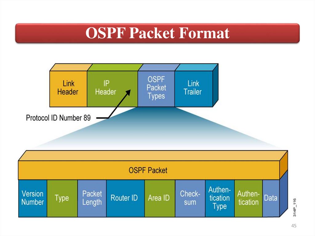
OSPF Packet Format45
46.
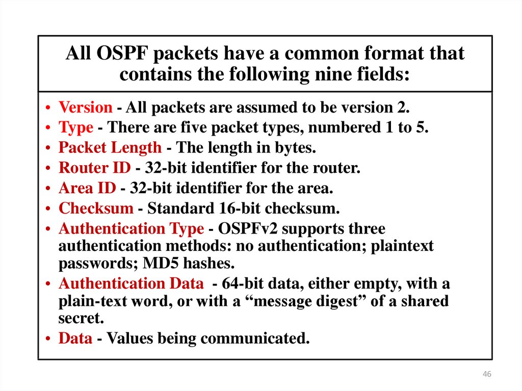
All OSPF packets have a common format thatcontains the following nine fields:
Version - All packets are assumed to be version 2.
Type - There are five packet types, numbered 1 to 5.
Packet Length - The length in bytes.
Router ID - 32-bit identifier for the router.
Area ID - 32-bit identifier for the area.
Checksum - Standard 16-bit checksum.
Authentication Type - OSPFv2 supports three
authentication methods: no authentication; plaintext
passwords; MD5 hashes.
• Authentication Data - 64-bit data, either empty, with a
plain-text word, or with a “message digest” of a shared
secret.
• Data - Values being communicated.
46
47. How OSPF Packet Processes Work
4748.
The OSPF HierarchyOSPF is a hierarchical system that separates an Autonomous
System into individual areas. OSPF traffic can either be intraarea (within one area), inter-area (between separate areas), or
external (from another AS).
OSPF routers build a Topology Database of all links within their
area, and all routers within an area will have an identical
topology database. Limiting the topology database to include
only the local area conserves bandwidth and reduces CPU loads.
48
49.
The OSPF HierarchyArea 0 is required for OSPF to function, and is considered
the “Backbone” area. As a rule, all other areas must have a
connection into Area 0. Area 0 is often referred to as the
transit area to connect all other areas.
OSPF routers can belong to multiple areas, and will thus
contain separate Topology databases for each area.
49
50.
The OSPF HierarchyBR
Internal Routers.
ABR
Three areas exist: Area 0, Area 1, and Area 2.
Area 0, again, is the backbone area for this Autonomous System. Both
Area 1 and Area 2 must directly connect to Area 0. Routers A and B
belong fully to Area 1, while Routers E and F belong fully to Area 2.
These are known as Internal Routers.
Router C belongs to both Area 0 and Area 1. Thus, it is an Area
Border Routers (ABR) and will thus contain separate Topology
databases for each area.
Because it has an interface in Area 0, it can also be considered a
Backbone Router (BR). The same can be said for Router D, as it
belongs to both Area 0 and Area 2.
50
51.
The OSPF HierarchyRouter G has been added,
which belongs to Area 0.
However, Router G also has
a connection to the Internet,
which is outside this
Autonomous System. This
makes Router G an
Autonomous System Border
Router (ASBR).
ASBRs provide access to external networks. OSPF defines two “types” of
external routes:
Type 2 (E2)
• Includes only the external cost to the destination network. External cost
is the metric being advertised from outside the OSPF domain.
Type 1 (E1)
• Includes both the external cost, and the internal cost to reach the ASBR.
Type 1 routes are always preferred over Type 2 routes to the same
destination.
51
52.
OSPF router typesThus, the four separate OSPF router types are as follows:
• Internal Routers
• all router interfaces belong to
only one Area.
• Area Border
• contains interfaces in at least
two separate areas
Routers (ABRs)
contain
at
least
one
interface
in
• Backbone Routers
Area 0
• Autonomous
System Border
Routers (ASBRs)
• contain a connection to a
separate Autonomous System
52
53.
OSPF Virtual LinksIt was stated that all areas must directly connect into Area 0, as a
rule. In the above example, Area 2 has no direct connection to Area 0,
but must transit through Area 1 to reach the backbone area.
Virtual links can be used as a workaround, to logically connect
separated areas to Area 0. In the above example, a virtual link would
essentially create a tunnel from Area 2 to Area 0, using Area 1 a
transit area.
53
54.
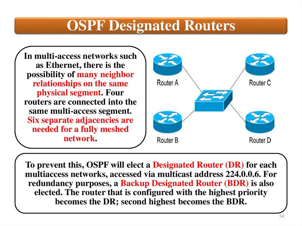
OSPF Designated RoutersIn multi-access networks such
as Ethernet, there is the
possibility of many neighbor
relationships on the same
physical segment. Four
routers are connected into the
same multi-access segment.
Six separate adjacencies are
needed for a fully meshed
network.
To prevent this, OSPF will elect a Designated Router (DR) for each
multiaccess networks, accessed via multicast address 224.0.0.6. For
redundancy purposes, a Backup Designated Router (BDR) is also
elected. The router that is configured with the highest priority
becomes the DR; second highest becomes the BDR.
54
55.
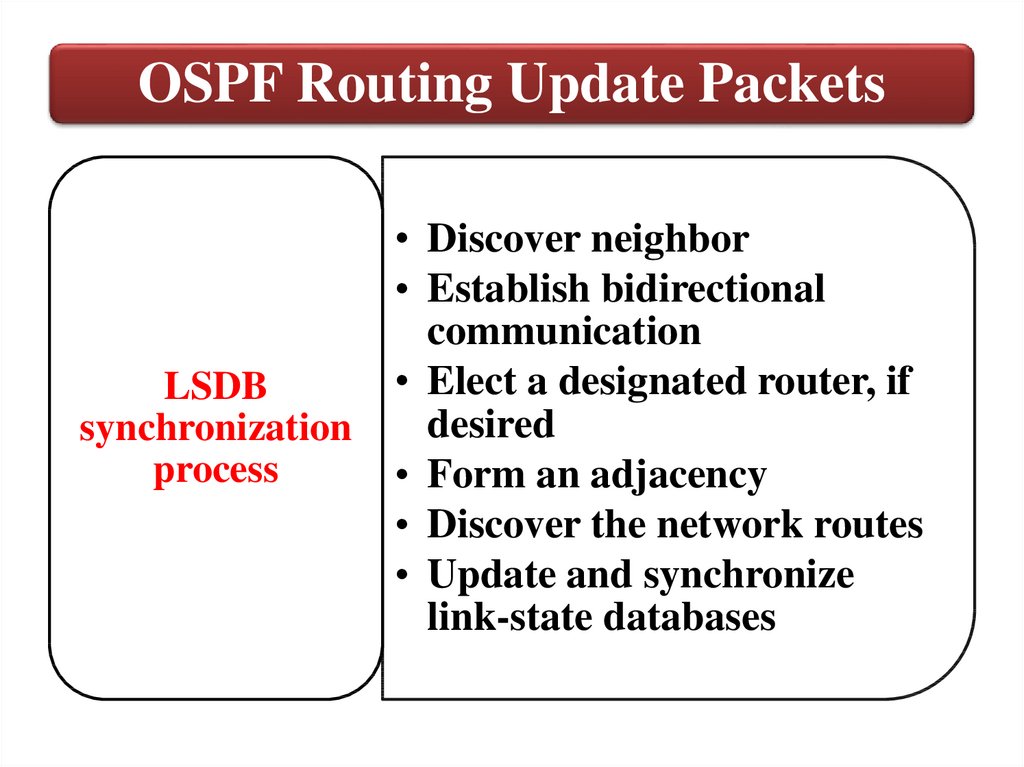
OSPF Routing Update PacketsLSDB
synchronization
process
• Discover neighbor
• Establish bidirectional
communication
• Elect a designated router, if
desired
• Form an adjacency
• Discover the network routes
• Update and synchronize
link-state databases
56.
Establishing Bidirectional Communication57.
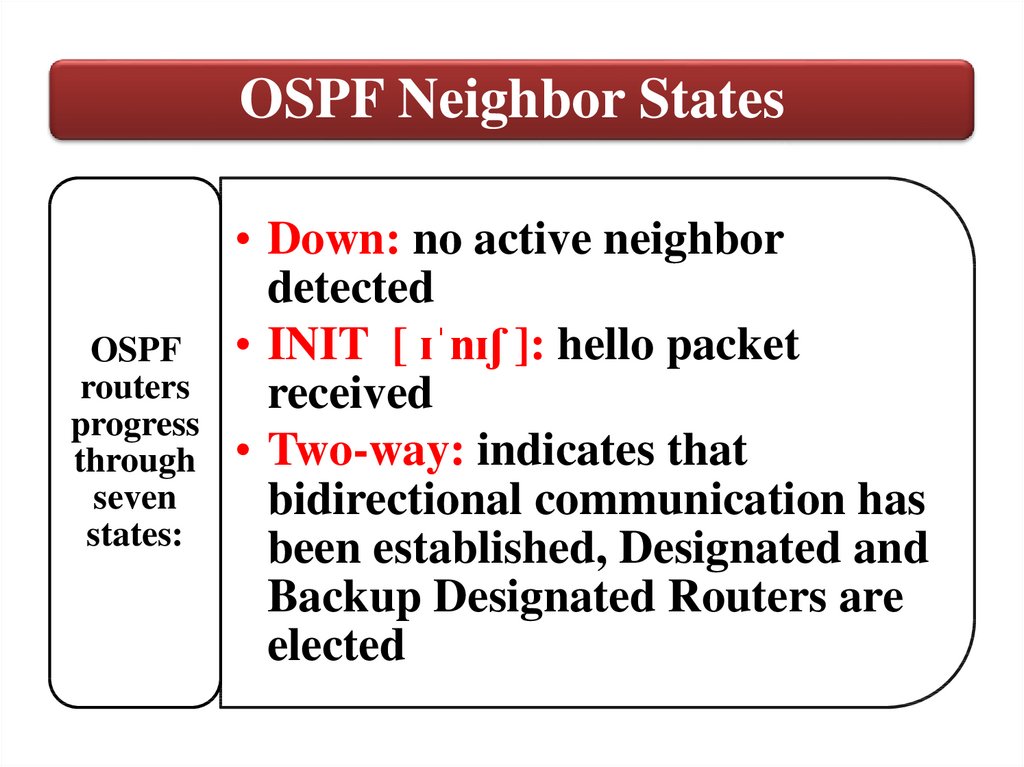
OSPF Neighbor StatesOSPF
routers
progress
through
seven
states:
• Down: no active neighbor
detected
• INIT [ ɪˈnɪʃ ]: hello packet
received
• Two-way: indicates that
bidirectional communication has
been established, Designated and
Backup Designated Routers are
elected
58.
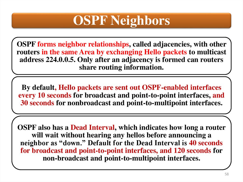
OSPF NeighborsOSPF forms neighbor relationships, called adjacencies, with other
routers in the same Area by exchanging Hello packets to multicast
address 224.0.0.5. Only after an adjacency is formed can routers
share routing information.
By default, Hello packets are sent out OSPF-enabled interfaces
every 10 seconds for broadcast and point-to-point interfaces, and
30 seconds for nonbroadcast and point-to-multipoint interfaces.
OSPF also has a Dead Interval, which indicates how long a router
will wait without hearing any hellos before announcing a
neighbor as “down.” Default for the Dead Interval is 40 seconds
for broadcast and point-to-point interfaces, and 120 seconds for
non-broadcast and point-to-multipoint interfaces.
58
59.
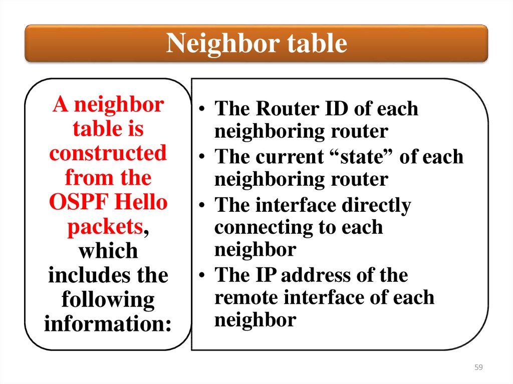
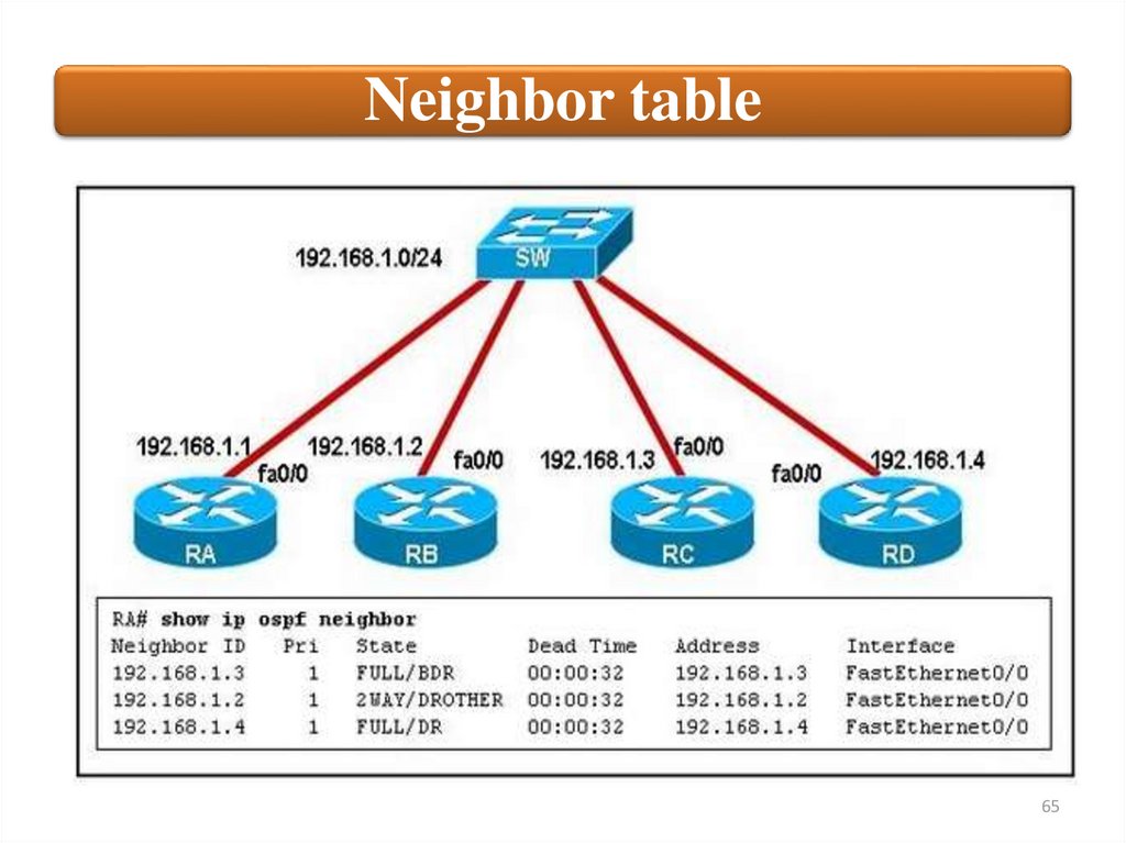
Neighbor tableA neighbor
table is
constructed
from the
OSPF Hello
packets,
which
includes the
following
information:
• The Router ID of each
neighboring router
• The current “state” of each
neighboring router
• The interface directly
connecting to each
neighbor
• The IP address of the
remote interface of each
neighbor
59
60.
Neighbor table60
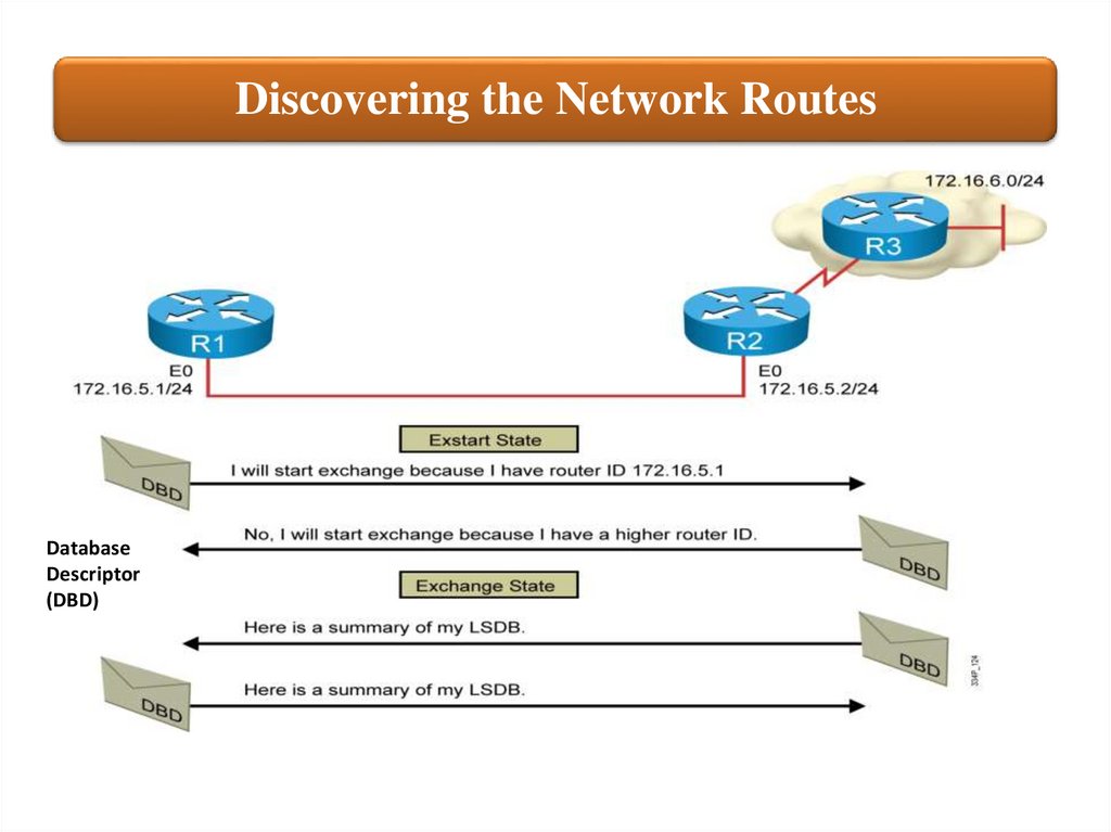
61.
Discovering the Network RoutesDatabase
Descriptor
(DBD)
62.
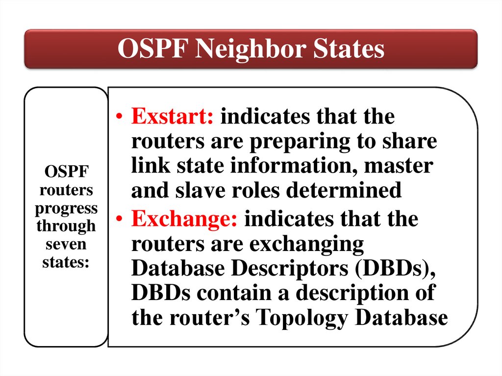
OSPF Neighbor StatesOSPF
routers
progress
through
seven
states:
• Exstart: indicates that the
routers are preparing to share
link state information, master
and slave roles determined
• Exchange: indicates that the
routers are exchanging
Database Descriptors (DBDs),
DBDs contain a description of
the router’s Topology Database
63.
Adding the Link-State EntriesLink State
Requests
(LSR)
Link State
update
(LSU)
64.
OSPF Neighbor States• Loading: indicates the routers are
finally exchanging Link State
Advertisements (LSA), containing
OSPF
information about all links connected
routers
to each router, exchange of LSRs and
progress
LSUs
through
• Full: indicates that the routers are fully
seven
synchronized, the topology table of all
states:
routers in the area should now be
identical. Its databases are
synchronized with adjacent routers.
65.
Neighbor table65
66.
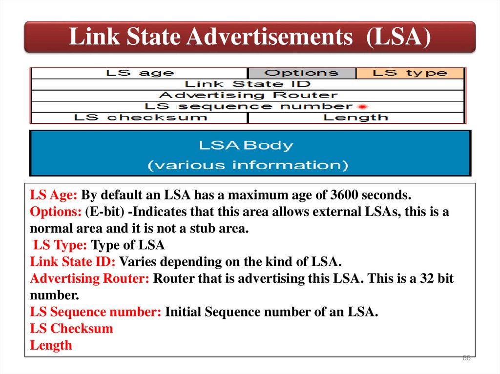
Link State Advertisements (LSA)LS Age: By default an LSA has a maximum age of 3600 seconds.
Options: (E-bit) -Indicates that this area allows external LSAs, this is a
normal area and it is not a stub area.
LS Type: Type of LSA
Link State ID: Varies depending on the kind of LSA.
Advertising Router: Router that is advertising this LSA. This is a 32 bit
number.
LS Sequence number: Initial Sequence number of an LSA.
LS Checksum
Length
66
67.
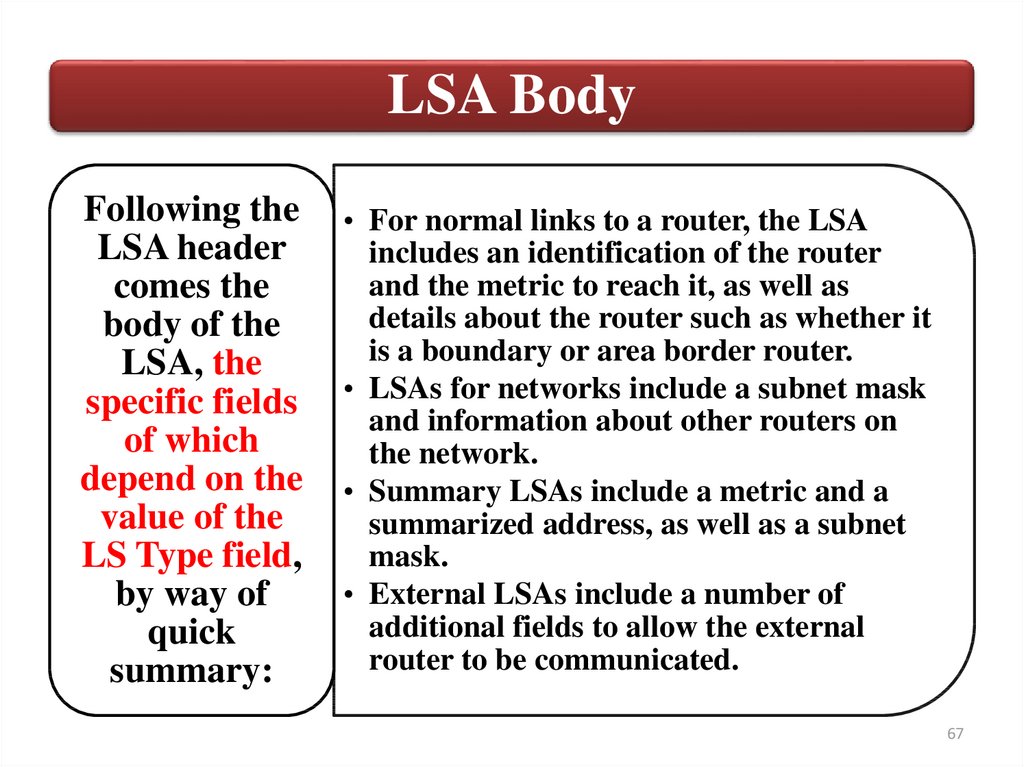
LSA BodyFollowing the
LSA header
comes the
body of the
LSA, the
specific fields
of which
depend on the
value of the
LS Type field,
by way of
quick
summary:
• For normal links to a router, the LSA
includes an identification of the router
and the metric to reach it, as well as
details about the router such as whether it
is a boundary or area border router.
• LSAs for networks include a subnet mask
and information about other routers on
the network.
• Summary LSAs include a metric and a
summarized address, as well as a subnet
mask.
• External LSAs include a number of
additional fields to allow the external
router to be communicated.
67
68.
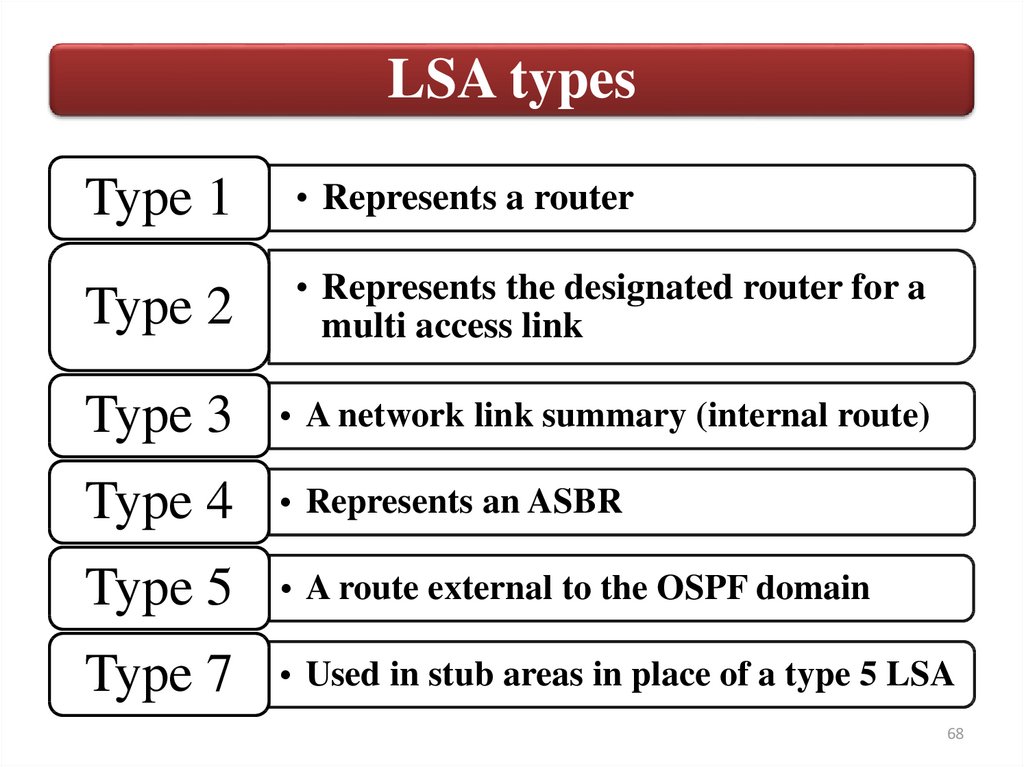
LSA typesType 1
• Represents a router
Type 2
• Represents the designated router for a
multi access link
Type 3
• A network link summary (internal route)
Type 4
• Represents an ASBR
Type 5
• A route external to the OSPF domain
Type 7
• Used in stub areas in place of a type 5 LSA
68
69.
Link State Database (LSDB)The LSDB is a database of all OSPF router LSAs, summary
LSAs, and external route LSAs. The LSDB is compiled by an
ongoing exchange of LSAs between neighboring routers so that
each router is synchronized with its neighbor. When the AS has
converged, all routers have the appropriate entries in their LSDB.
69
70.
Use SPF algorithm to select best pathOnce each router knows about all the other routers and the links
connecting them, it runs the Dijkstra Shortest Path First
algorithm to determine the shortest path from itself to all the
other routers in the network. Since each router has a similar copy
of the link state database and each runs the same algorithm, they
end up constructing the same view of the network and packets
get routed consistently at each hop.
70
71.
Routing tableAlso called forwarding table contain only the best
path to forward data traffic
71
72.
Flooding Changes in TopologyRouter R1 that detects a topology change adjusts its LSA and floods
the LSA:
• Router R1 notifies all OSPF neighbors using 224.0.0.5, or, on LAN
links, all OSPF DRs and BDRs using 224.0.0.6.
• The DR notifies others on 224.0.0.5.
• The LSDBs of all routers must be synchronized.
73.
Дякую за увагу73