


 internet
Similar presentations:


Lecture 3. Switches
1.
Lecture 3Switches
1
2.
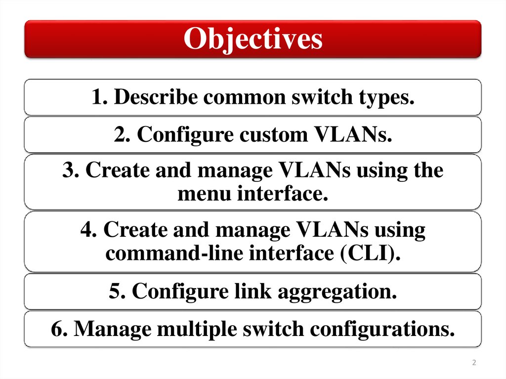
Objectives1. Describe common switch types.
2. Configure custom VLANs.
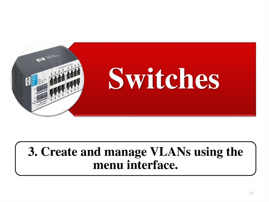
3. Create and manage VLANs using the
menu interface.
4. Create and manage VLANs using
command-line interface (CLI).
5. Configure link aggregation.
6. Manage multiple switch configurations.
2
3.
Switches1. Describe common switch types
3
4.
SwitchesThere are many different types of network switches
according to the management and configuration option,
number of LAN ports, maximum data rate.
The various types of switches contained in a network are:
Unmanaged switch
Smart managed switch
Managed switch
4
5.
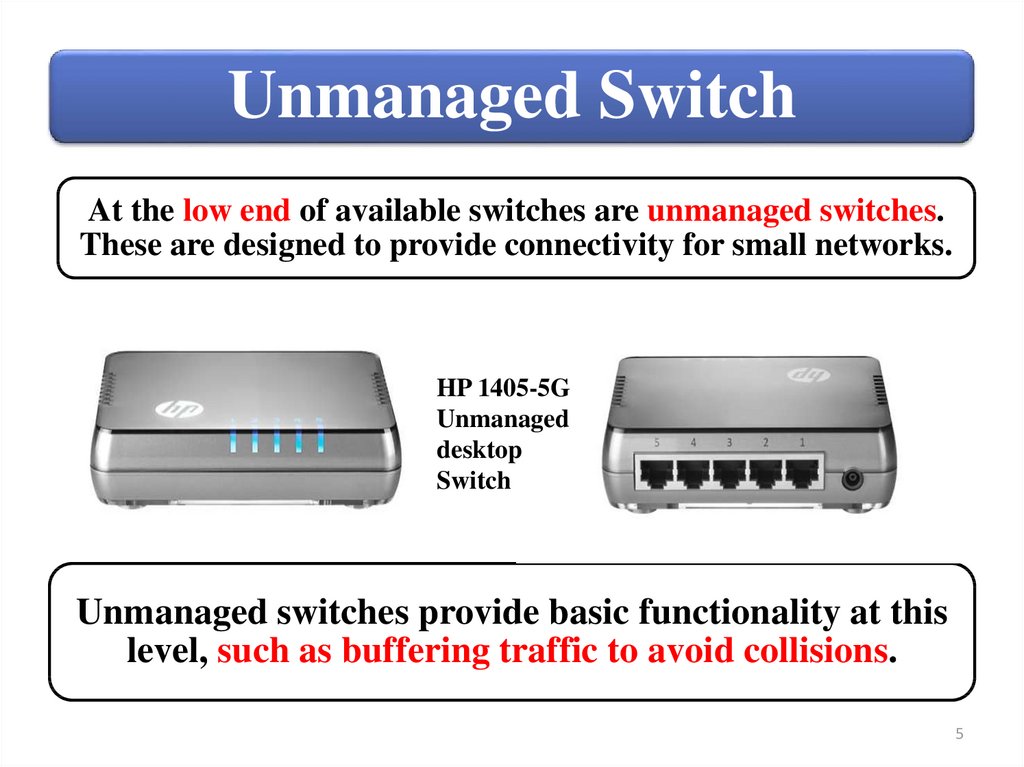
Unmanaged SwitchAt the low end of available switches are unmanaged switches.
These are designed to provide connectivity for small networks.
HP 1405-5G
Unmanaged
desktop
Switch
Unmanaged switches provide basic functionality at this
level, such as buffering traffic to avoid collisions.
5
6.
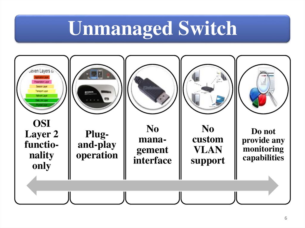
Unmanaged SwitchOSI
Layer 2
functionality
only
Plugand-play
operation
No
management
interface
No
custom
VLAN
support
Do not
provide any
monitoring
capabilities
6
7.
Smart Managed SwitchSwitch, also known as a web managed switch, support limited
management options. They are, however, more advanced devices
than unmanaged switches and support additional functionality.
HP 1620-24G 24-PORT
10/100/1000 Gigabit Smart
Managed Switch
Most smart managed switches provide
functionality at OSI Layer 2, but a small
number include some Layer 3
functionality, including support for simple
IP routing.
Routing support is usually limited to
static routes only.
Like unmanaged switches, smart managed
switches can typically be deployed as
plug‐and‐play devices using their default
configurations.
7
8.
Smart Managed Switch AdvantagesSmart managed
switch has
management access
through a
browser‐based
management
interface, which
allows to view port
statistics and
manage custom
configurations.
Another clear
advantage is that
smart managed
switches include
VLAN support.
You can also
configure link
aggregation to
provide a high‐
bandwidth data
path.
8
9.
Smart Managed Switch LimitedLimited
functionality
• Most switches of this type also have an RJ‐45
console port. Some also have a USB
connection that can be used to connect
directly to the switch. This is similar to the
console connection on managed switches, but
it can typically be used to perform the same
procedures as the web interface.
• Smart managed switches also include limited
SNMP support. SNMP management devices
can automatically discover and remotely
monitor smart managed switches. However,
smart managed switches do not support
remote management from an SNMP
management device.
9
10.
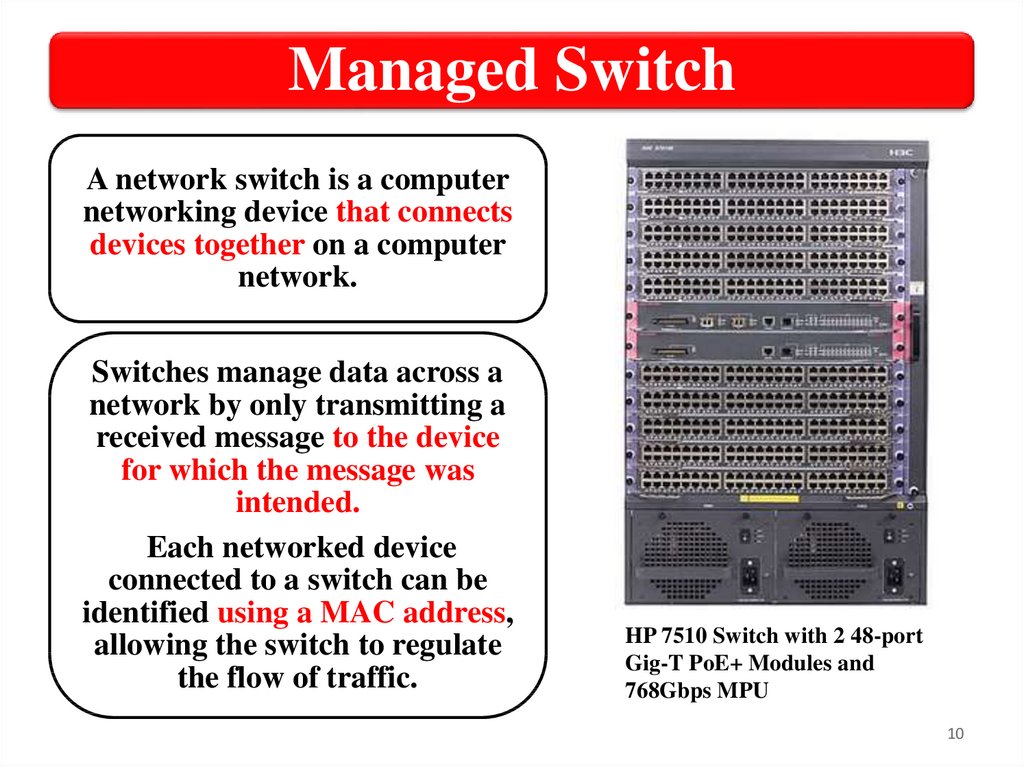
Managed SwitchA network switch is a computer
networking device that connects
devices together on a computer
network.
Switches manage data across a
network by only transmitting a
received message to the device
for which the message was
intended.
Each networked device
connected to a switch can be
identified using a MAC address,
allowing the switch to regulate
the flow of traffic.
HP 7510 Switch with 2 48-port
Gig-T PoE+ Modules and
768Gbps MPU
10
11.
Managed Switch functionalityManaged switches support OSI Layer
2 functionality as well as a wide array
of Layer 3 functionality, such as
dynamic routing.
• Support for dynamic updates to
Dynamic
network destinations and routes
to allow for changes in available
routing.
routes and network conditions.
11
12.
Managed Switch interfacesThese switches support a variety of
manual management options, including:
• CLI (console port or over the network);
• Menu interface (console port or over the
network);
• Web interface (over the network only).
12
13.
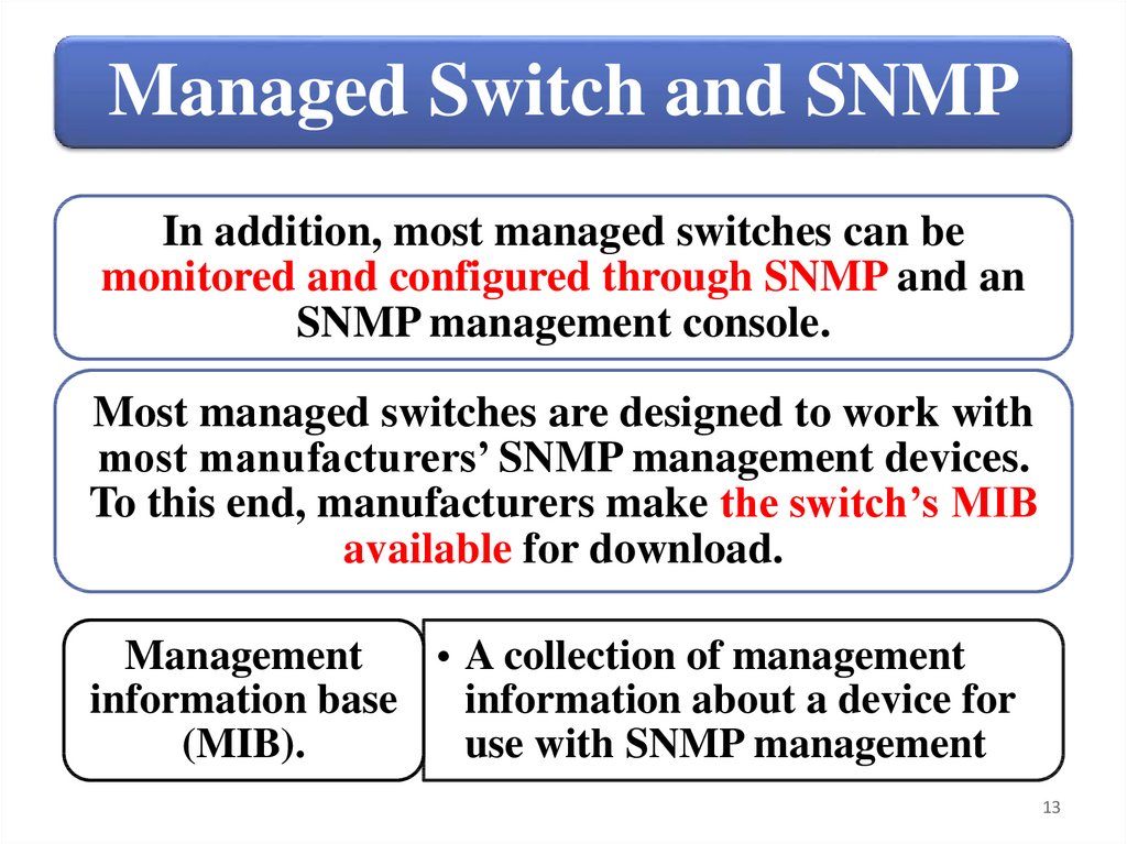
Managed Switch and SNMPIn addition, most managed switches can be
monitored and configured through SNMP and an
SNMP management console.
Most managed switches are designed to work with
most manufacturers’ SNMP management devices.
To this end, manufacturers make the switch’s MIB
available for download.
Management
• A collection of management
information base
information about a device for
(MIB).
use with SNMP management
13
14.
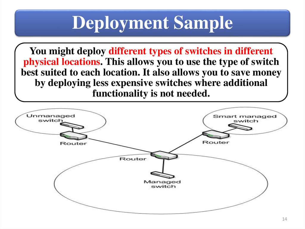
Deployment SampleYou might deploy different types of switches in different
physical locations. This allows you to use the type of switch
best suited to each location. It also allows you to save money
by deploying less expensive switches where additional
functionality is not needed.
14
15.
SummarySwitch
management
categories
• Unmanaged switch
• Smart managed
switch
• Managed switch
Switch deployment
15
16.
Switches2. Configure custom VLANs
16
17.
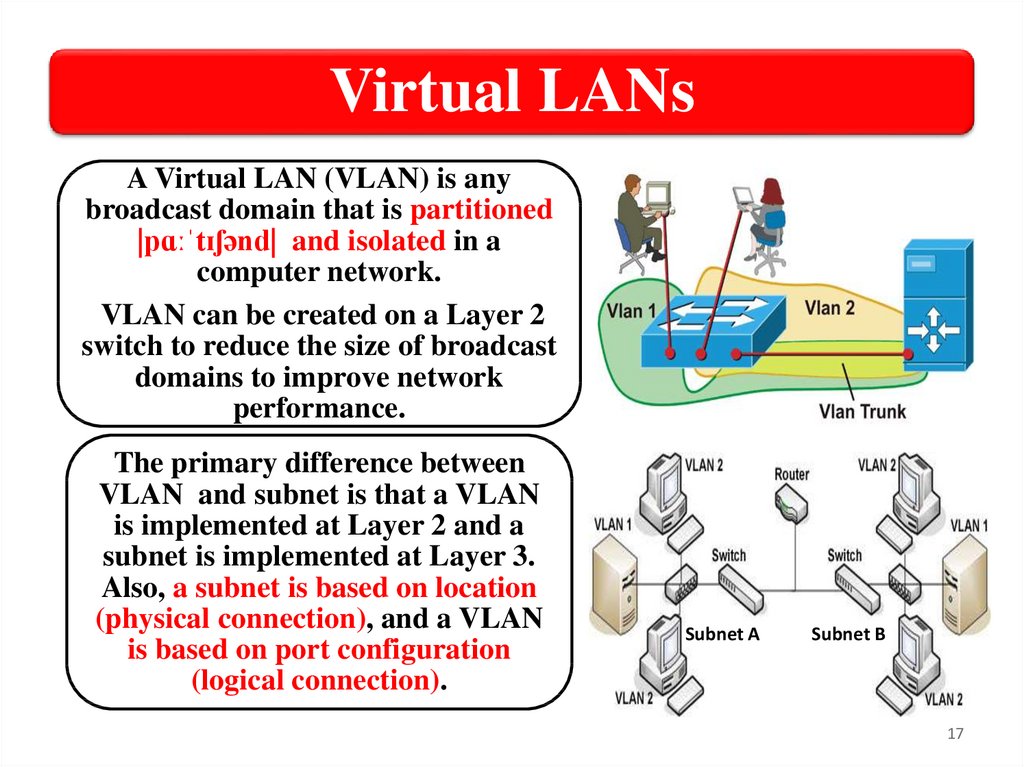
Virtual LANsA Virtual LAN (VLAN) is any
broadcast domain that is partitioned
|pɑːˈtɪʃənd| and isolated in a
computer network.
VLAN can be created on a Layer 2
switch to reduce the size of broadcast
domains to improve network
performance.
The primary difference between
VLAN and subnet is that a VLAN
is implemented at Layer 2 and a
subnet is implemented at Layer 3.
Also, a subnet is based on location
(physical connection), and a VLAN
is based on port configuration
(logical connection).
Subnet A
Subnet B
17
18.
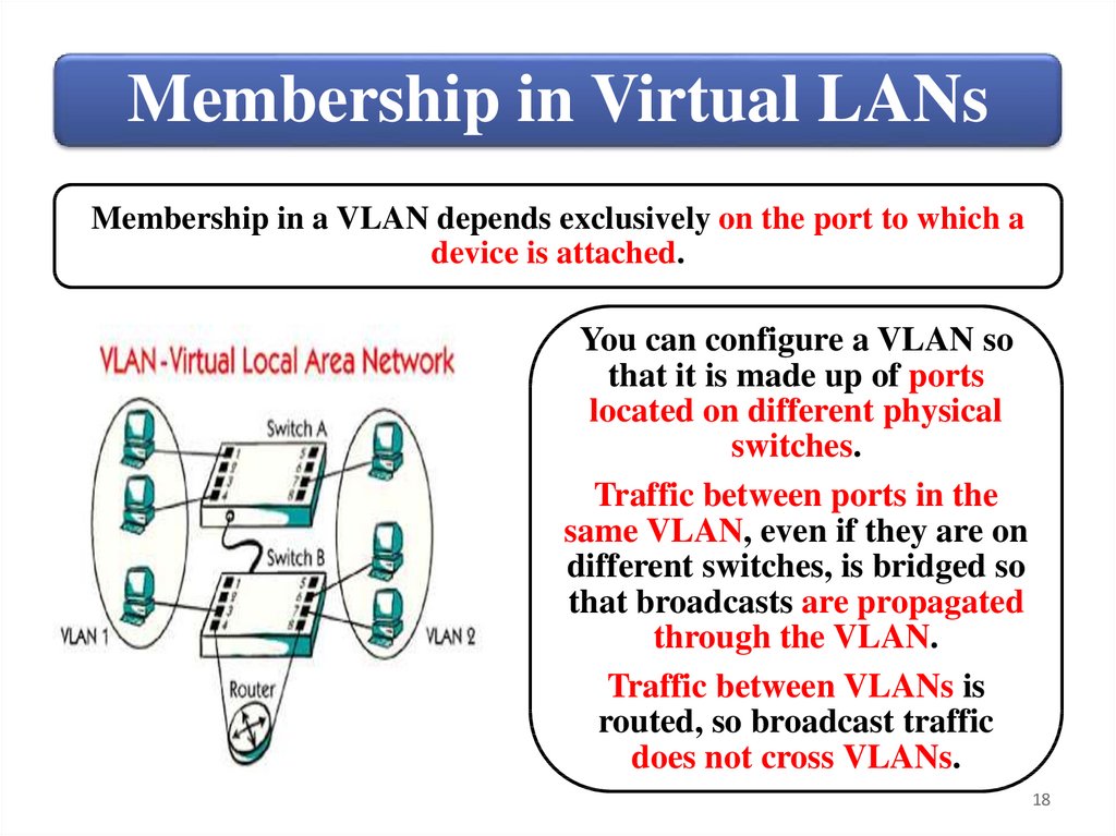
Membership in Virtual LANsMembership in a VLAN depends exclusively on the port to which a
device is attached.
You can configure a VLAN so
that it is made up of ports
located on different physical
switches.
Traffic between ports in the
same VLAN, even if they are on
different switches, is bridged so
that broadcasts are propagated
through the VLAN.
Traffic between VLANs is
routed, so broadcast traffic
does not cross VLANs.
18
19.
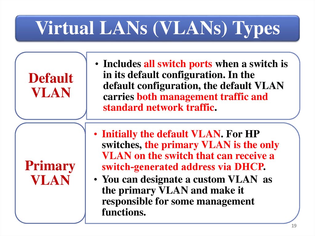
Virtual LANs (VLANs) TypesDefault
VLAN
Primary
VLAN
• Includes all switch ports when a switch is
in its default configuration. In the
default configuration, the default VLAN
carries both management traffic and
standard network traffic.
• Initially the default VLAN. For HP
switches, the primary VLAN is the only
VLAN on the switch that can receive a
switch‐generated address via DHCP.
• You can designate a custom VLAN as
the primary VLAN and make it
responsible for some management
functions.
19
20.
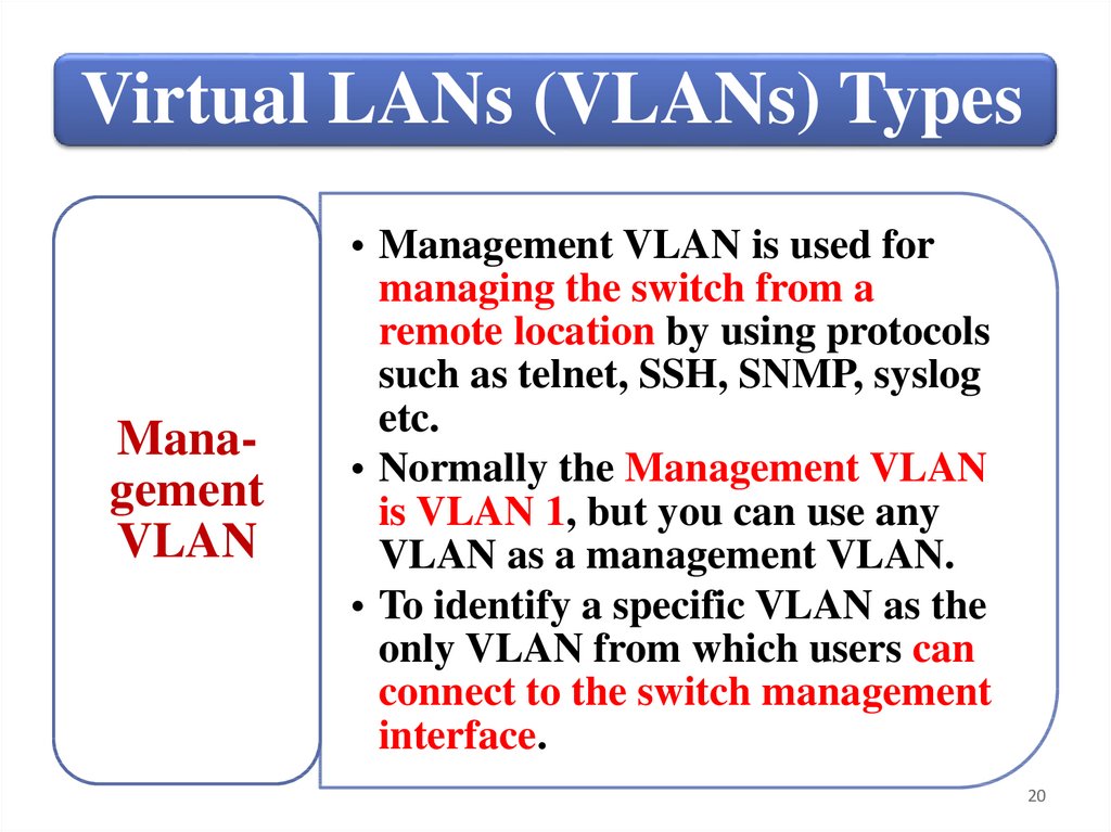
Virtual LANs (VLANs) TypesManagement
VLAN
• Management VLAN is used for
managing the switch from a
remote location by using protocols
such as telnet, SSH, SNMP, syslog
etc.
• Normally the Management VLAN
is VLAN 1, but you can use any
VLAN as a management VLAN.
• To identify a specific VLAN as the
only VLAN from which users can
connect to the switch management
interface.
20
21.
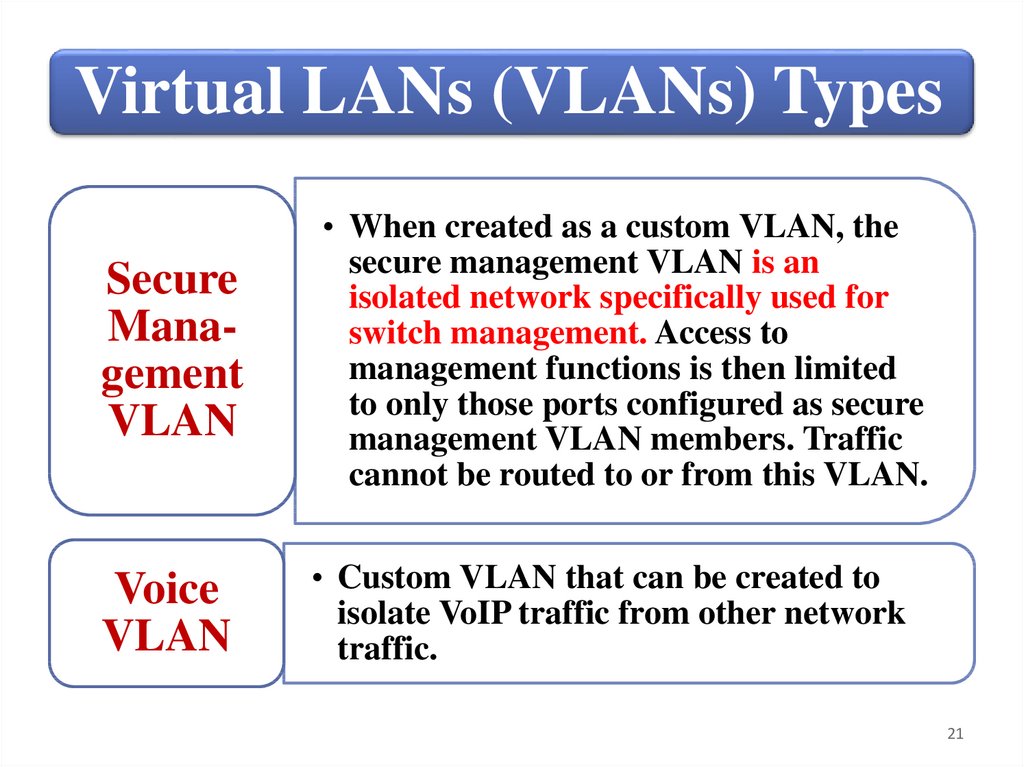
Virtual LANs (VLANs) TypesSecure
Management
VLAN
Voice
VLAN
• When created as a custom VLAN, the
secure management VLAN is an
isolated network specifically used for
switch management. Access to
management functions is then limited
to only those ports configured as secure
management VLAN members. Traffic
cannot be routed to or from this VLAN.
• Custom VLAN that can be created to
isolate VoIP traffic from other network
traffic.
21
22.
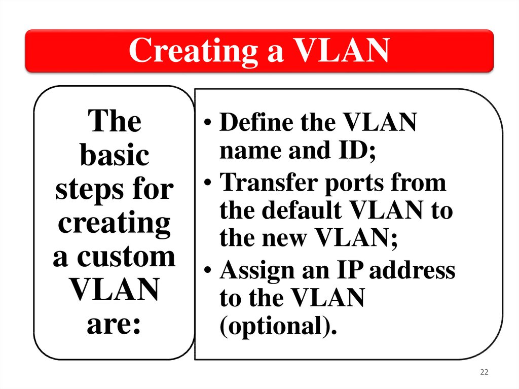
Creating a VLAN• Define the VLAN
The
name and ID;
basic
steps for • Transfer ports from
the default VLAN to
creating the new VLAN;
a custom • Assign an IP address
VLAN
to the VLAN
are:
(optional).
22
23.
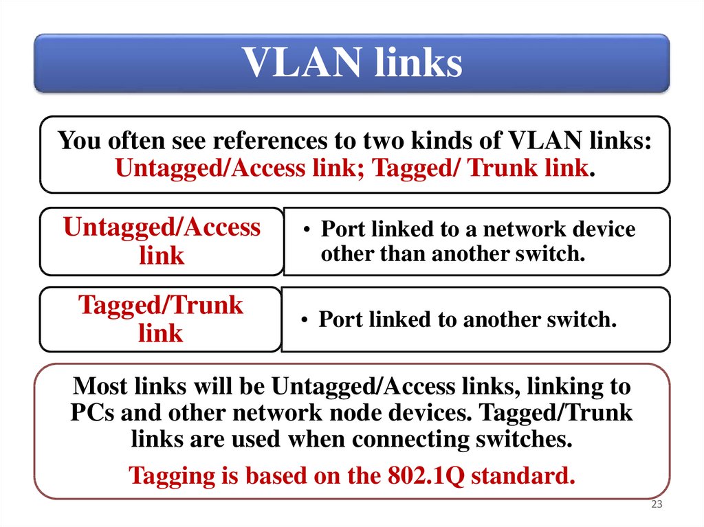
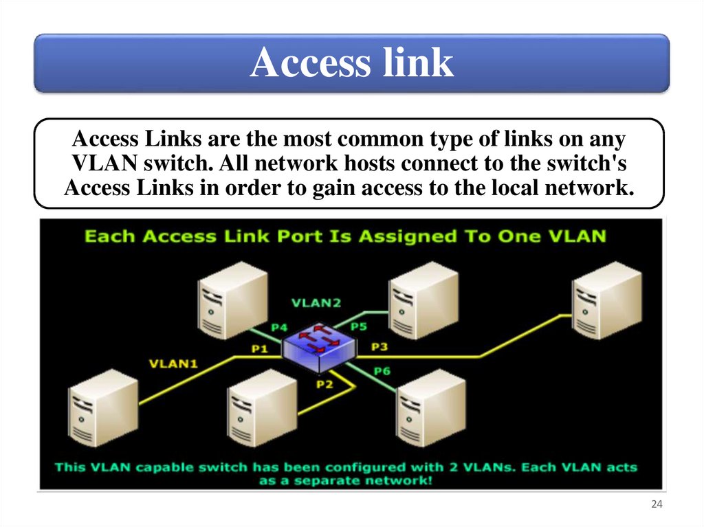
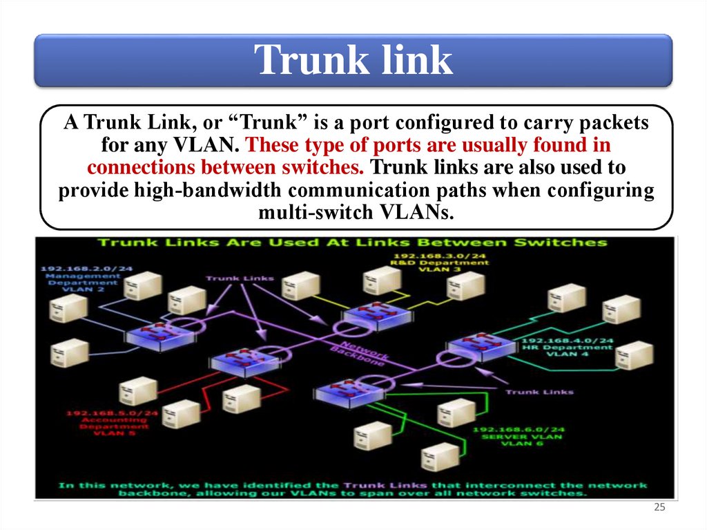
VLAN linksYou often see references to two kinds of VLAN links:
Untagged/Access link; Tagged/ Trunk link.
Untagged/Access
link
Tagged/Trunk
link
• Port linked to a network device
other than another switch.
• Port linked to another switch.
Most links will be Untagged/Access links, linking to
PCs and other network node devices. Tagged/Trunk
links are used when connecting switches.
Tagging is based on the 802.1Q standard.
23
24.
Access linkAccess Links are the most common type of links on any
VLAN switch. All network hosts connect to the switch's
Access Links in order to gain access to the local network.
24
25.
Trunk linkA Trunk Link, or “Trunk” is a port configured to carry packets
for any VLAN. These type of ports are usually found in
connections between switches. Trunk links are also used to
provide high‐bandwidth communication paths when configuring
multi‐switch VLANs.
25
26.
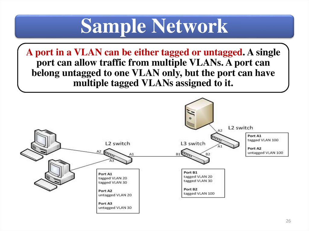
Sample NetworkA port in a VLAN can be either tagged or untagged. A single
port can allow traffic from multiple VLANs. A port can
belong untagged to one VLAN only, but the port can have
multiple tagged VLANs assigned to it.
26
27.
SummaryVLAN types and use
Creating and managing custom
VLANs
Viewing and managing ports
27
28.
Switches3. Create and manage VLANs using the
menu interface.
28
29.
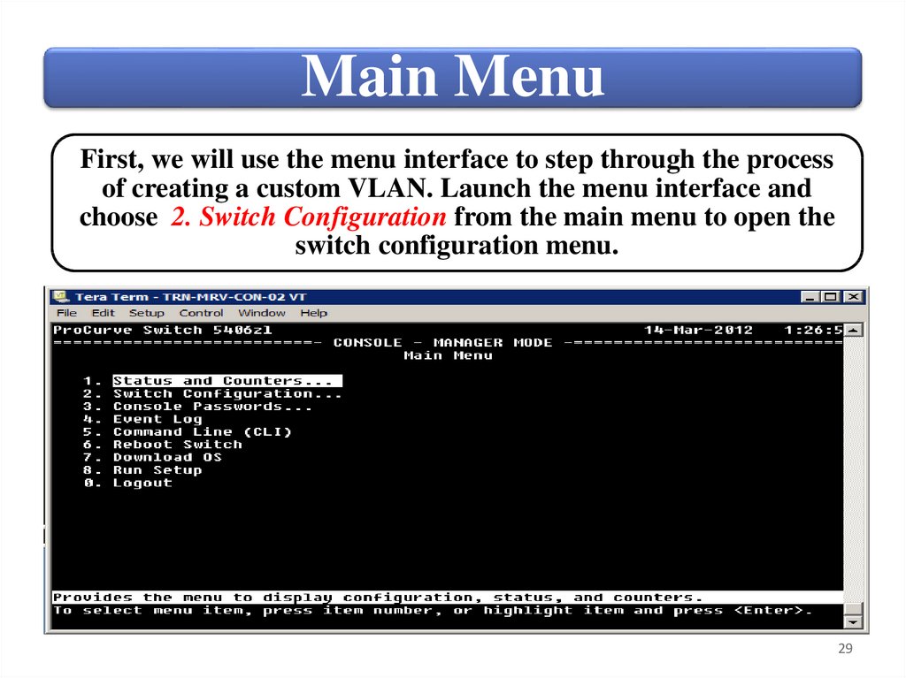
Main MenuFirst, we will use the menu interface to step through the process
of creating a custom VLAN. Launch the menu interface and
choose 2. Switch Configuration from the main menu to open the
switch configuration menu.
29
30.
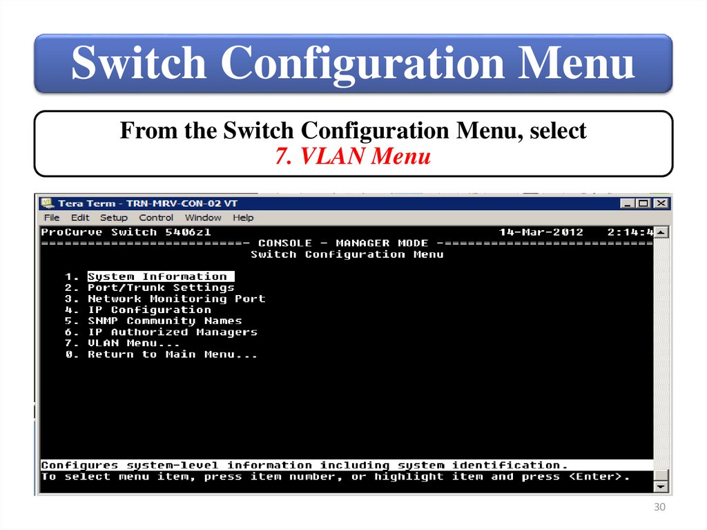
Switch Configuration MenuFrom the Switch Configuration Menu, select
7. VLAN Menu
30
31.
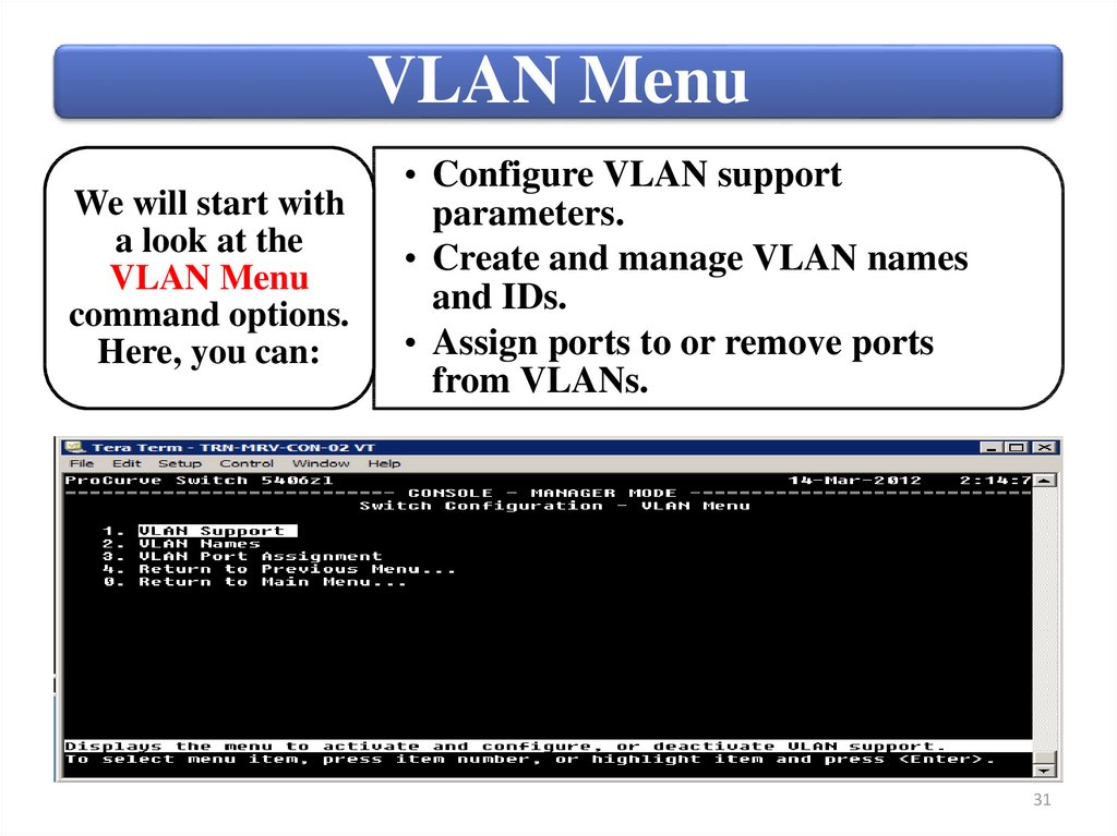
VLAN MenuWe will start with
a look at the
VLAN Menu
command options.
Here, you can:
• Configure VLAN support
parameters.
• Create and manage VLAN names
and IDs.
• Assign ports to or remove ports
from VLANs.
31
32.
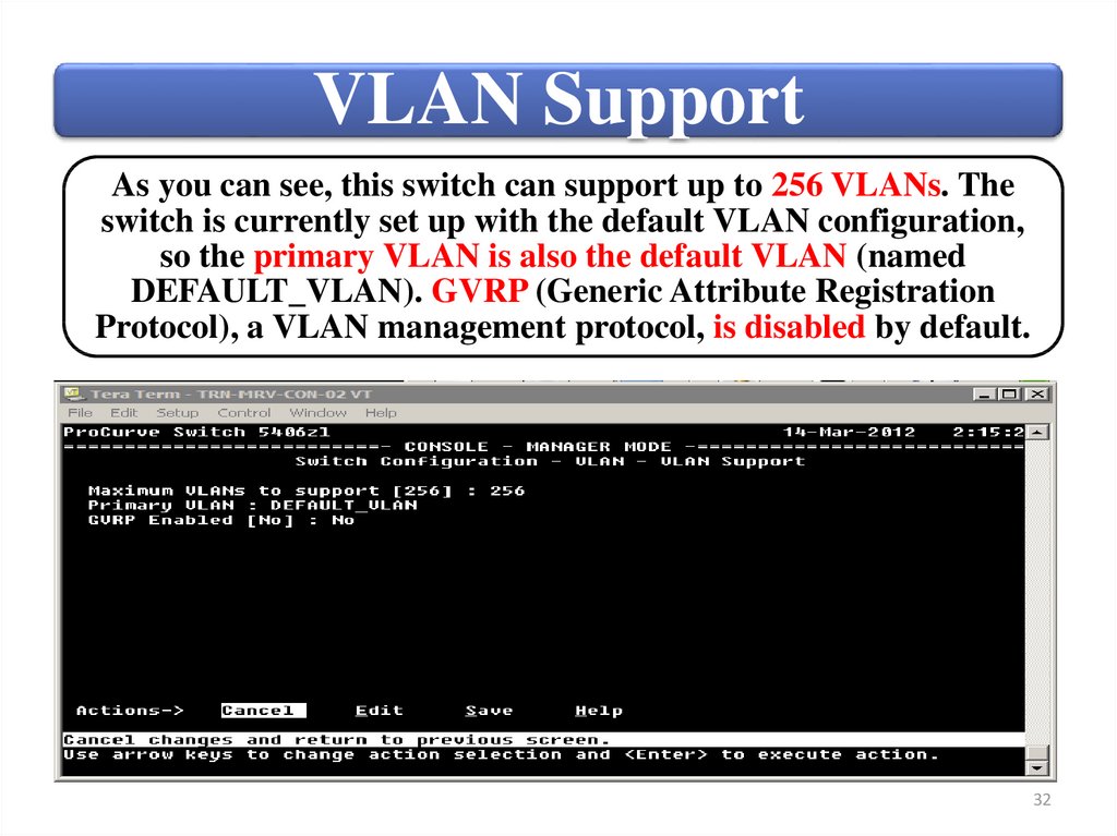
VLAN SupportAs you can see, this switch can support up to 256 VLANs. The
switch is currently set up with the default VLAN configuration,
so the primary VLAN is also the default VLAN (named
DEFAULT_VLAN). GVRP (Generic Attribute Registration
Protocol), a VLAN management protocol, is disabled by default.
32
33.
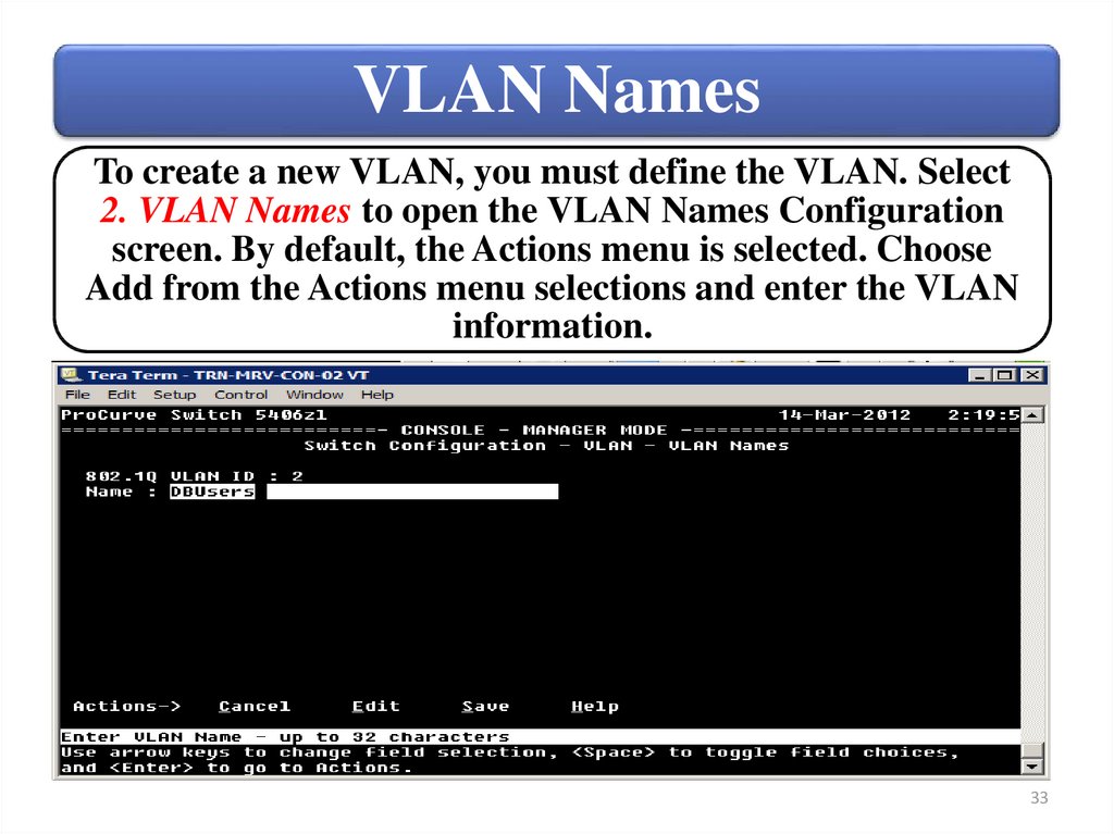
VLAN NamesTo create a new VLAN, you must define the VLAN. Select
2. VLAN Names to open the VLAN Names Configuration
screen. By default, the Actions menu is selected. Choose
Add from the Actions menu selections and enter the VLAN
information.
33
34.
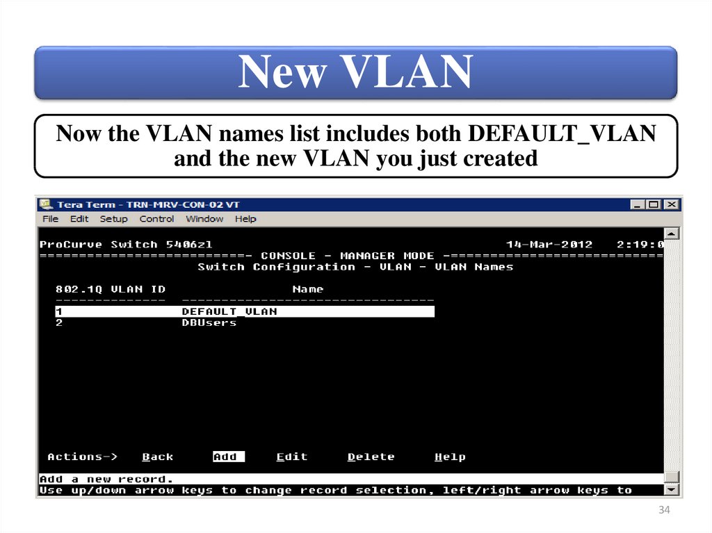
New VLANNow the VLAN names list includes both DEFAULT_VLAN
and the new VLAN you just created
34
35.
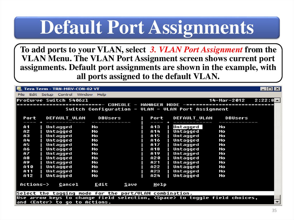
Default Port AssignmentsTo add ports to your VLAN, select 3. VLAN Port Assignment from the
VLAN Menu. The VLAN Port Assignment screen shows current port
assignments. Default port assignments are shown in the example, with
all ports assigned to the default VLAN.
35
36.
Selected PortTo change the port assignments, select Edit from the Actions menu
and use the arrow keys to select the port you want to change
36
37.
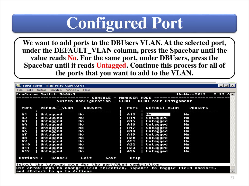
Configured PortWe want to add ports to the DBUsers VLAN. At the selected port,
under the DEFAULT_VLAN column, press the Spacebar until the
value reads No. For the same port, under DBUsers, press the
Spacebar until it reads Untagged. Continue this process for all of
the ports that you want to add to the VLAN.
37
38.
Switch Configuration MenuIP Configuration is disabled by default for a newly created VLAN.
You can reach this screen by selecting 4. IP Configuration from the
Switch Configuration Menu (Main menu).
38
39.
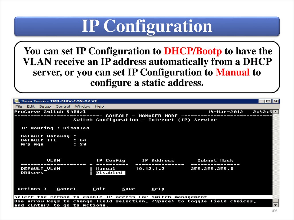
IP ConfigurationYou can set IP Configuration to DHCP/Bootp to have the
VLAN receive an IP address automatically from a DHCP
server, or you can set IP Configuration to Manual to
configure a static address.
39
40.
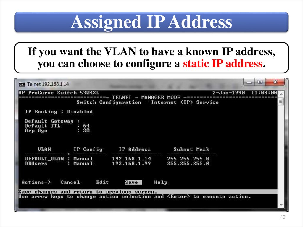
Assigned IP AddressIf you want the VLAN to have a known IP address,
you can choose to configure a static IP address.
40
41.
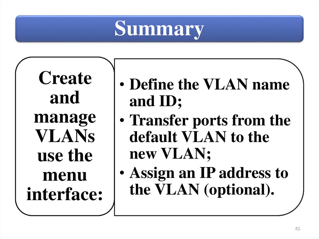
SummaryCreate • Define the VLAN name
and
and ID;
manage • Transfer ports from the
VLANs
default VLAN to the
new VLAN;
use the
• Assign an IP address to
menu
interface: the VLAN (optional).
41
42.
Switches4. Create and manage VLANs using
command-line interface (CLI)
42
43.
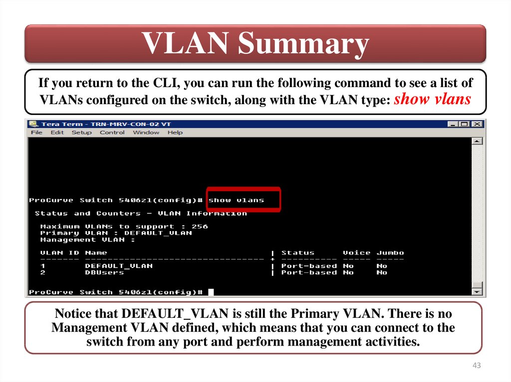
VLAN SummaryIf you return to the CLI, you can run the following command to see a list of
VLANs configured on the switch, along with the VLAN type: show vlans
Notice that DEFAULT_VLAN is still the Primary VLAN. There is no
Management VLAN defined, which means that you can connect to the
switch from any port and perform management activities.
43
44.
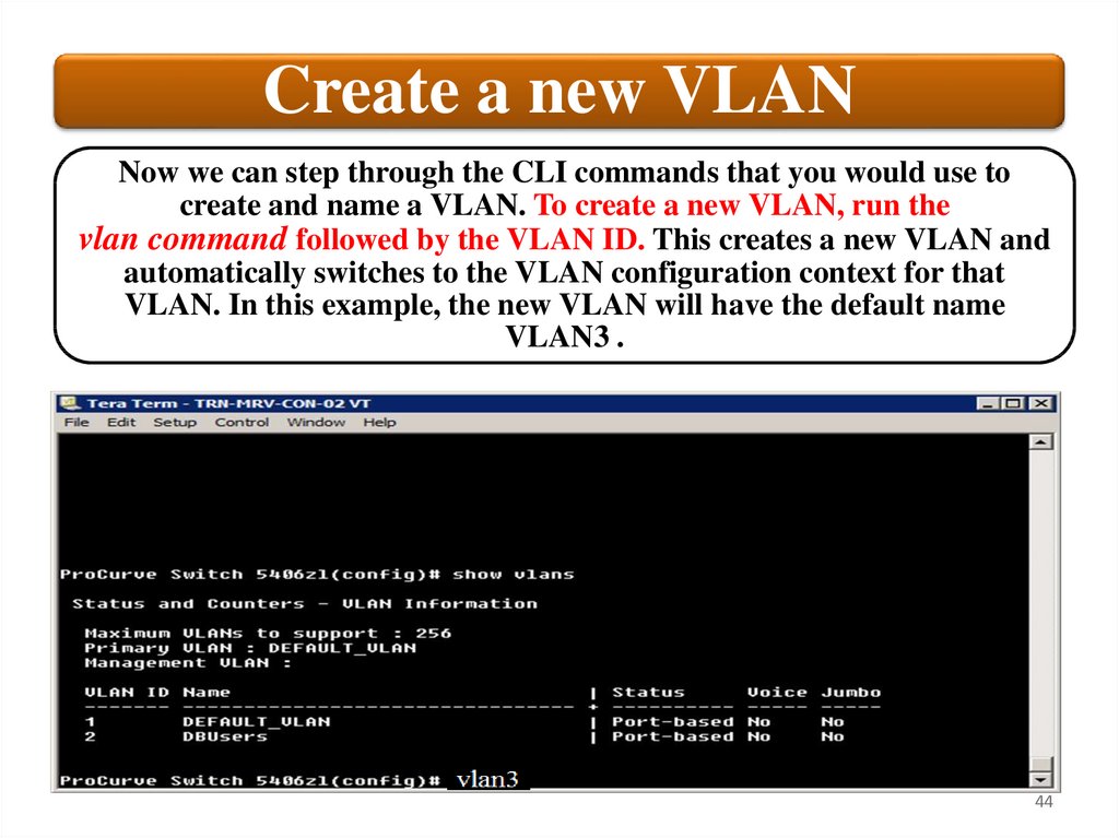
Create a new VLANNow we can step through the CLI commands that you would use to
create and name a VLAN. To create a new VLAN, run the
vlan command followed by the VLAN ID. This creates a new VLAN and
automatically switches to the VLAN configuration context for that
VLAN. In this example, the new VLAN will have the default name
VLAN3 .
44
45.
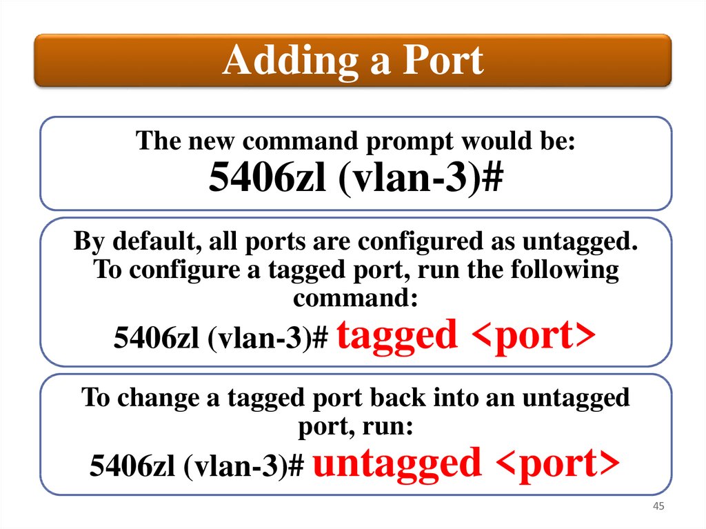
Adding a PortThe new command prompt would be:
5406zl (vlan-3)#
By default, all ports are configured as untagged.
To configure a tagged port, run the following
command:
5406zl (vlan-3)# tagged
<port>
To change a tagged port back into an untagged
port, run:
5406zl (vlan-3)# untagged
<port>
45
46.
Default VLAN NameIf you want
to rename
the VLAN as
Work1, you
would run:
• 5406zl (vlan-3)#
name Work1
• 5406zl (config)#
vlan VLAN3 name
Work1
46
47.
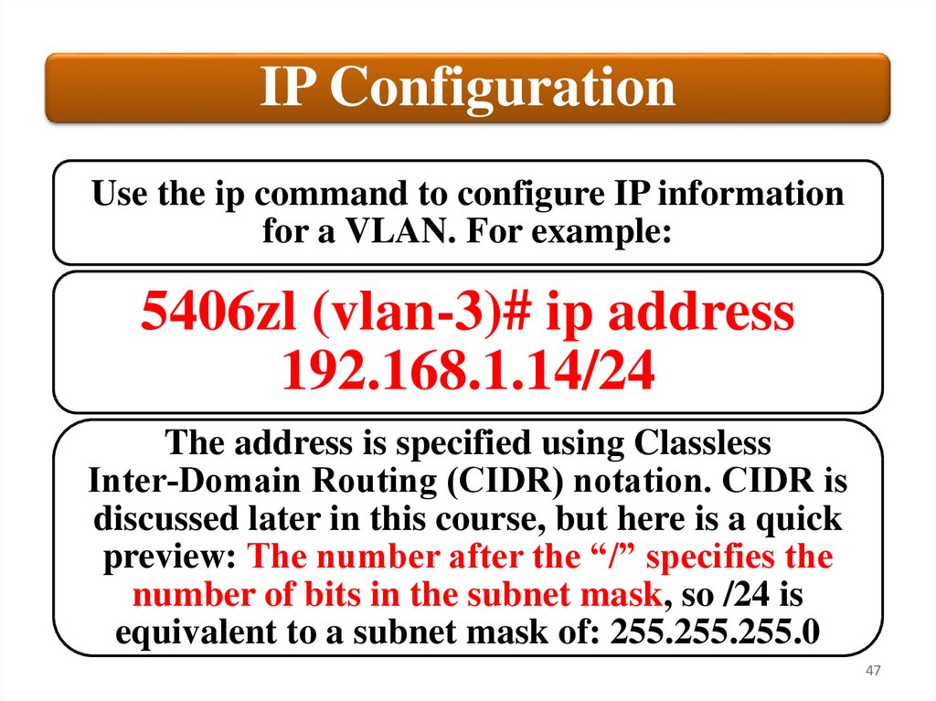
IP ConfigurationUse the ip command to configure IP information
for a VLAN. For example:
5406zl (vlan-3)# ip address
192.168.1.14/24
The address is specified using Classless
Inter‐Domain Routing (CIDR) notation. CIDR is
discussed later in this course, but here is a quick
preview: The number after the “/” specifies the
number of bits in the subnet mask, so /24 is
equivalent to a subnet mask of: 255.255.255.0
47
48.
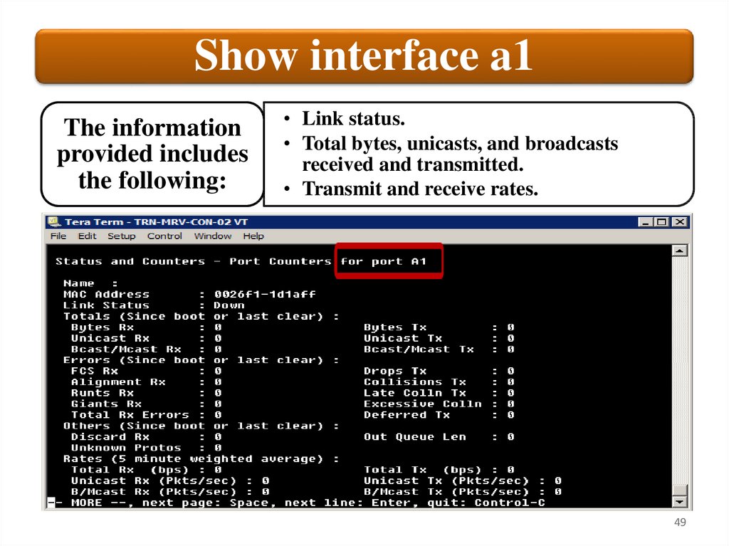
Port managementPort management for VLANs is done under the vlan
context. However, you can view most port information,
including statistics and counters, from any context. To
view a port summary for the switch, run the following
command:
show interface
If you want to see detailed port counter information for
a single port, include the port number:
show interface 1
This will give you detailed port statistics for the specified
port.
48
49.
Show interface a1The information
provided includes
the following:
• Link status.
• Total bytes, unicasts, and broadcasts
received and transmitted.
• Transmit and receive rates.
49
50.
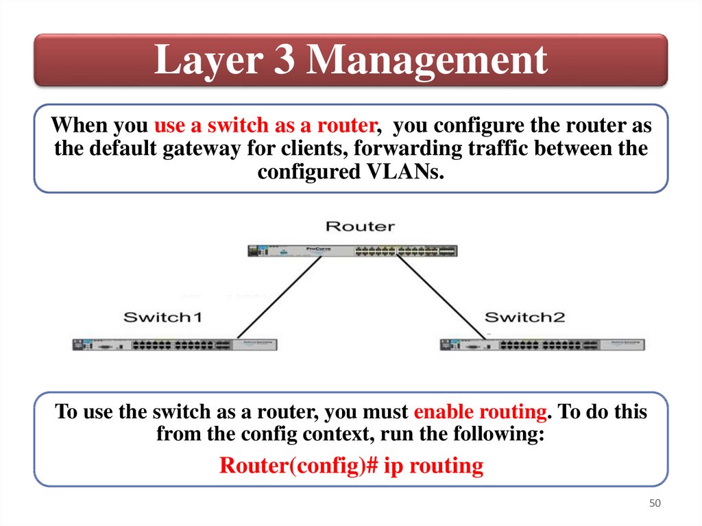
Layer 3 ManagementWhen you use a switch as a router, you configure the router as
the default gateway for clients, forwarding traffic between the
configured VLANs.
To use the switch as a router, you must enable routing. To do this
from the config context, run the following:
Router(config)# ip routing
50
51.
Configure default gatewayYou must configure the edge switches with a default gateway.
The default gateway must be in same subnet as the management
IP address of the Router.
This is done from the edge switch in the config context. Assuming
a default gateway address of 192.168.10.1, run the following:
Switch1(config)# ip default-gateway 192.168.10.1
You can use the ping command to test communication from a
switch to a connected device. To test connectivity from Router to
a device connected to one of the edge switches, you would run a
command similar to the following:
Router# ping 192.168.1.108
51
52.
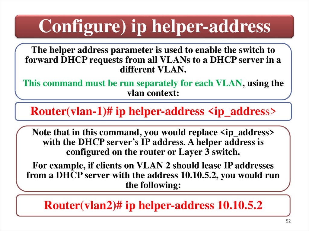
Configure) ip helper-addressThe helper address parameter is used to enable the switch to
forward DHCP requests from all VLANs to a DHCP server in a
different VLAN.
This command must be run separately for each VLAN, using the
vlan context:
Router(vlan-1)# ip helper-address <ip_address>
Note that in this command, you would replace <ip_address>
with the DHCP server’s IP address. A helper address is
configured on the router or Layer 3 switch.
For example, if clients on VLAN 2 should lease IP addresses
from a DHCP server with the address 10.10.5.2, you would run
the following:
Router(vlan2)# ip helper-address 10.10.5.2
52
53.
SummaryCreate and manage VLANs using
command-line interface (CLI)
Port management
Layer 3 Management
53
54.
Switches5. Configure link aggregation
54
55.
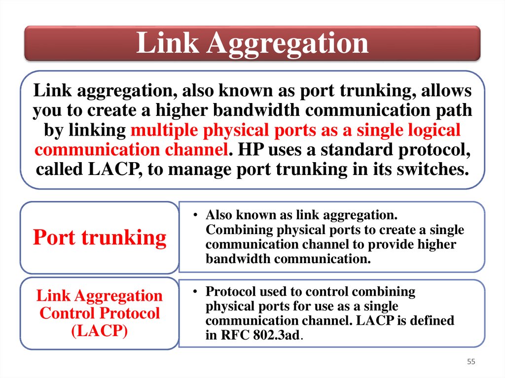
Link AggregationLink aggregation, also known as port trunking, allows
you to create a higher bandwidth communication path
by linking multiple physical ports as a single logical
communication channel. HP uses a standard protocol,
called LACP, to manage port trunking in its switches.
Port trunking
• Also known as link aggregation.
Combining physical ports to create a single
communication channel to provide higher
bandwidth communication.
Link Aggregation
Control Protocol
(LACP)
• Protocol used to control combining
physical ports for use as a single
communication channel. LACP is defined
in RFC 802.3ad.
55
56.
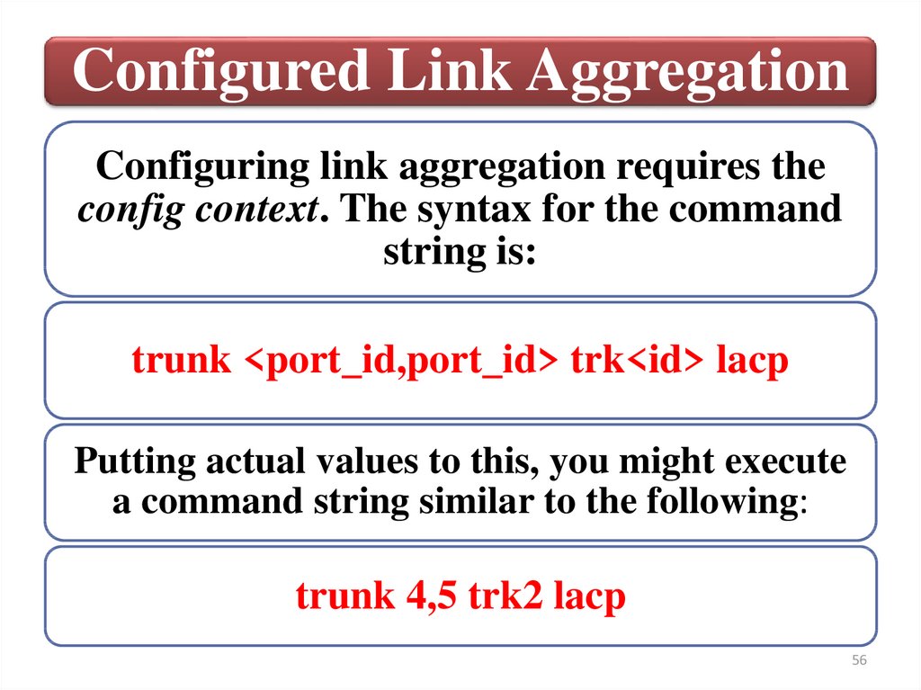
Configured Link AggregationConfiguring link aggregation requires the
config context. The syntax for the command
string is:
trunk <port_id,port_id> trk<id> lacp
Putting actual values to this, you might execute
a command string similar to the following:
trunk 4,5 trk2 lacp
56
57.
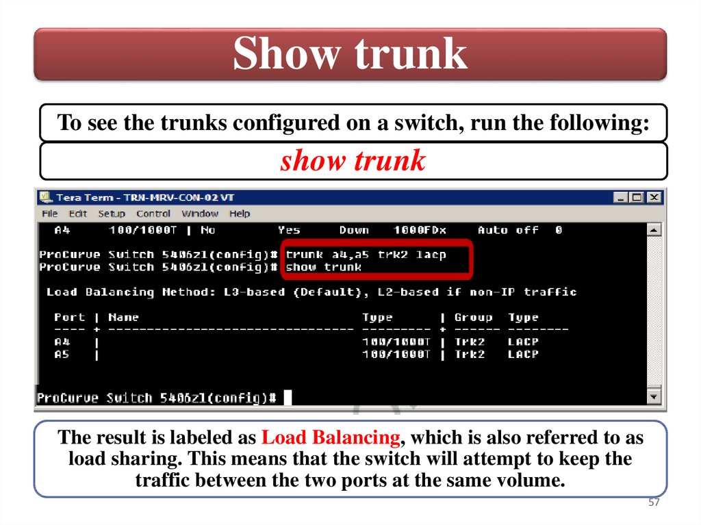
Show trunkTo see the trunks configured on a switch, run the following:
show trunk
The result is labeled as Load Balancing, which is also referred to as
load sharing. This means that the switch will attempt to keep the
traffic between the two ports at the same volume.
57
58.
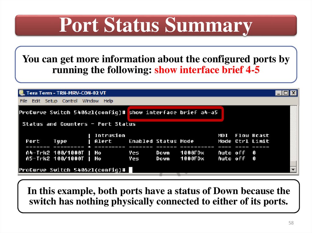
Port Status SummaryYou can get more information about the configured ports by
running the following: show interface brief 4-5
In this example, both ports have a status of Down because the
switch has nothing physically connected to either of its ports.
58
59.
Associate a trunkTo associate a trunk with a VLAN, execute the
following in the config context:
vlan <id> tagged trk<id>
For example, to associate trunk 2 with VLAN 10,
run the following: vlan 10 tagged trk2
59
60.
SummaryConfigured Link Aggregation
Port Status Summary
Associate a trunk
60
61.
Switches6. Manage multiple switch configurations
61
62.
Configuration managementBefore working with the switch configuration, you should
verify that the running configuration and the startup
configuration are the same.
You can view the running configuration by executing the
following:
show running-config
To compare the running configuration with the saved startup
configuration, run the following:
show running-config status
If the two are different, remember that you can run the
write memory command to save the running configuration
as the new startup configuration.
62
63.
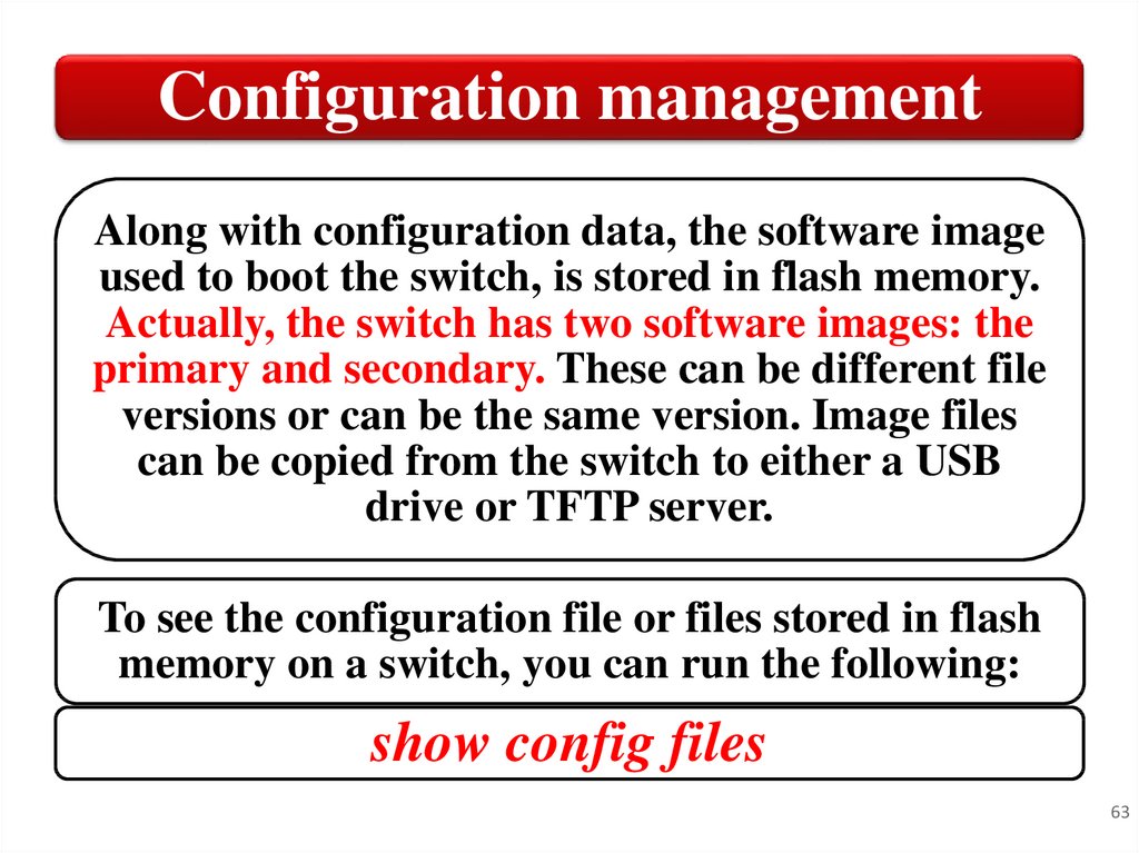
Configuration managementAlong with configuration data, the software image
used to boot the switch, is stored in flash memory.
Actually, the switch has two software images: the
primary and secondary. These can be different file
versions or can be the same version. Image files
can be copied from the switch to either a USB
drive or TFTP server.
To see the configuration file or files stored in flash
memory on a switch, you can run the following:
show config files
63
64.
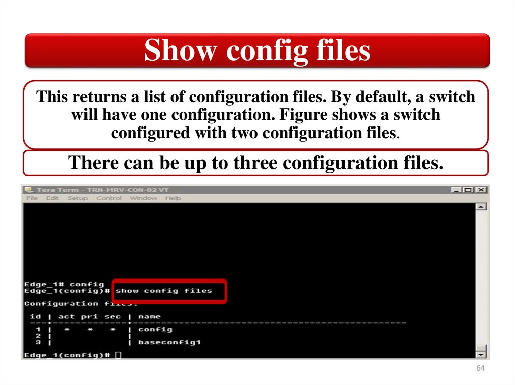
Show config filesThis returns a list of configuration files. By default, a switch
will have one configuration. Figure shows a switch
configured with two configuration files.
There can be up to three configuration files.
64
65.
Configuration Filesact
• This is the active configuration,
that is, the configuration used
to boot the switch.
pri
• The configuration associated
with the primary software
image.
sec
• The configuration associated
with the secondary software
image.
65
66.
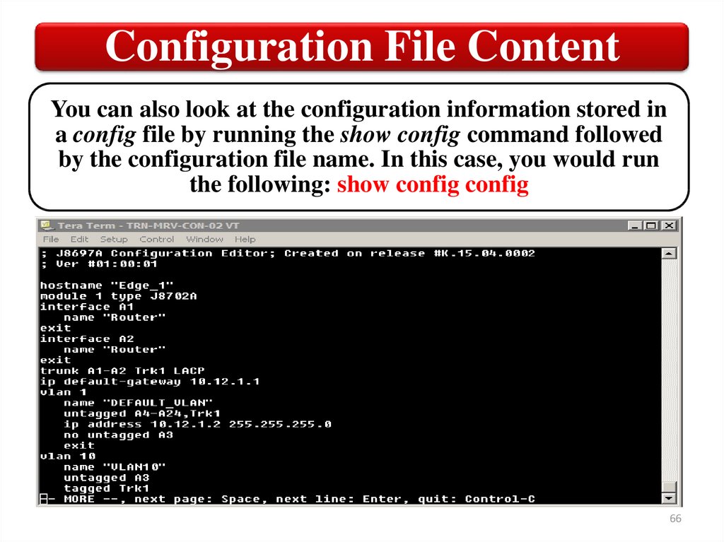
Configuration File ContentYou can also look at the configuration information stored in
a config file by running the show config command followed
by the configuration file name. In this case, you would run
the following: show config config
66
67.
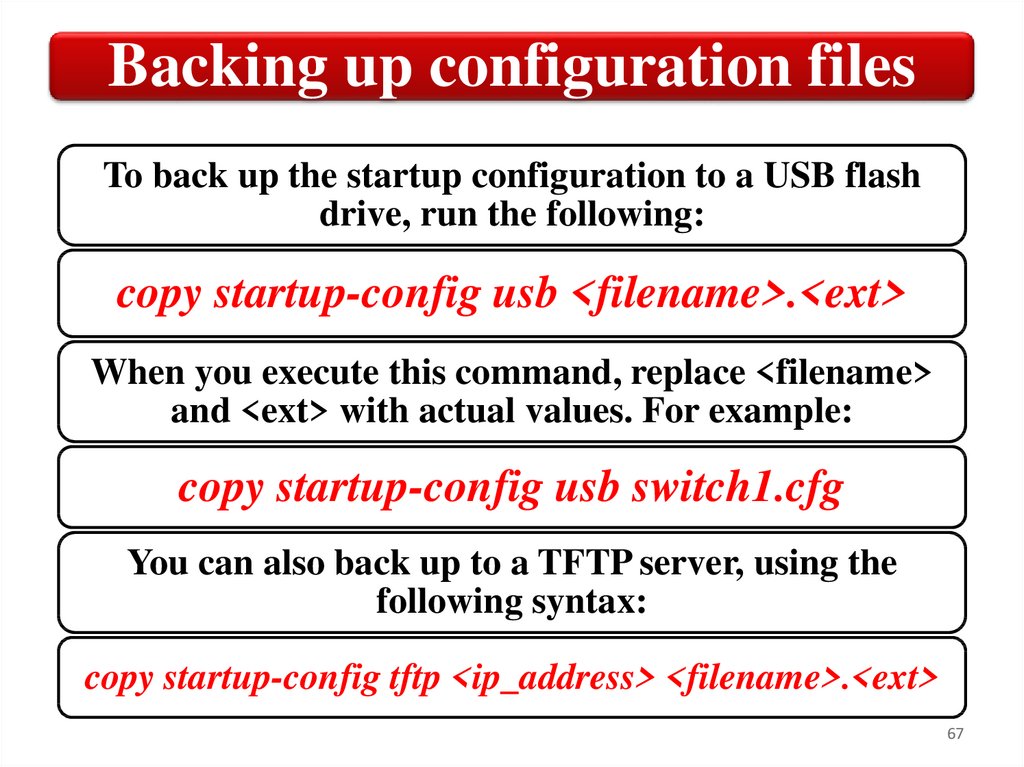
Backing up configuration filesTo back up the startup configuration to a USB flash
drive, run the following:
copy startup-config usb <filename>.<ext>
When you execute this command, replace <filename>
and <ext> with actual values. For example:
copy startup-config usb switch1.cfg
You can also back up to a TFTP server, using the
following syntax:
copy startup-config tftp <ip_address> <filename>.<ext>
67
68.
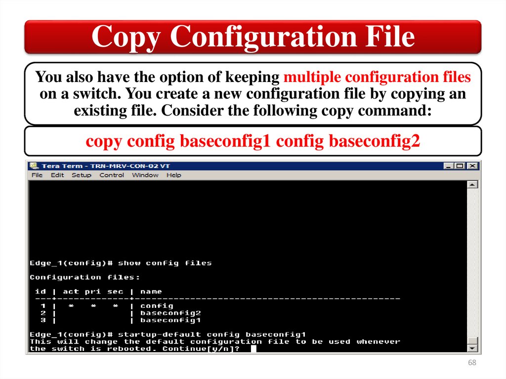
Copy Configuration FileYou also have the option of keeping multiple configuration files
on a switch. You create a new configuration file by copying an
existing file. Consider the following copy command:
copy config baseconfig1 config baseconfig2
68
69.
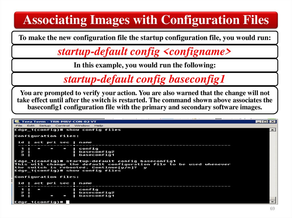
Associating Images with Configuration FilesTo make the new configuration file the startup configuration file, you would run:
startup-default config <configname>
In this example, you would run the following:
startup-default config baseconfig1
You are prompted to verify your action. You are also warned that the change will not
take effect until after the switch is restarted. The command shown above associates the
baseconfig1 configuration file with the primary and secondary software images.
69
70.
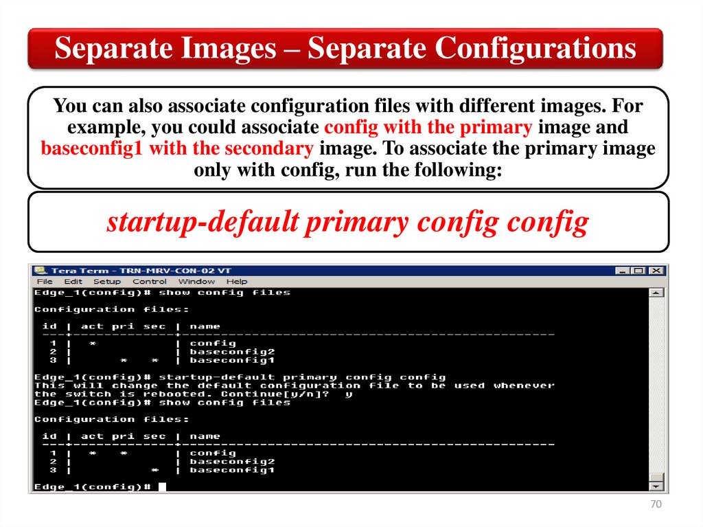
Separate Images – Separate ConfigurationsYou can also associate configuration files with different images. For
example, you could associate config with the primary image and
baseconfig1 with the secondary image. To associate the primary image
only with config, run the following:
startup-default primary config config
70
71.
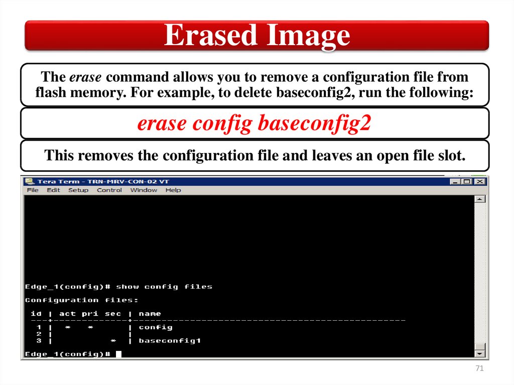
Erased ImageThe erase command allows you to remove a configuration file from
flash memory. For example, to delete baseconfig2, run the following:
erase config baseconfig2
This removes the configuration file and leaves an open file slot.
71
72.
Erased ImageIf you erase the active configuration file, you are
prompted to replace it with your other configuration
file. In this case, you would get the following message:
The specified configuration file
"baseconfig1" is the default configuration
for the primary and/or secondary boot image.
If it is deleted, the current active
configuration file "config" will be set as the
default. Erase anyway [y/n]?
Press the y key to have the file reconfigured for you.
72
73.
Show flashSwitch software is stored in flash memory along with the startup
configuration file. There are two software images, which are identified
as the primary and secondary images. By default, the switch is
configured to boot from the primary image.
73
74.
Using the secondary imageOne option for updating system software is to download the file to
a USB drive and then apply the image to the switch’s flash
memory. To copy the software as the secondary image, run:
copy usb flash <filename> secondary
This leaves the primary copy unchanged. Specify “primary” at the
end of the command string if you want to copy the file from the
USB drive to flash memory.
After copying the image to flash memory, your next step should be to
boot from the image to make sure that it works properly. To initiate a
one‐time boot using the secondary image, run the following:
boot system flash secondary
74
75.
SummaryСonfiguration files
Backing up configuration files
Startup configuration file
Erase configuration file
Flash memory
75