

 electronics
Similar presentations:


 Wireless Audio - Soundbar ’2017 SAMSUNG ELECTRONICS CO.,LTD. VD R&D GROUP")


")


Universal Serial Bus. Micro-USB Cables and Connectors
1.
Universal Serial BusMicro-USB Cables and Connectors
Specification
Revision 1.01
April 4, 2007
2.
MicroUSB Specification to the USB 2.0 Specification, Revision 1.01April 4, 2007
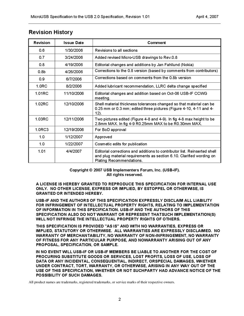
Revision History
Revision
Issue Date
Comment
0.6
1/30/2006
Revisions to all sections
0.7
3/24/2006
Added revised Micro-USB drawings to Rev.0.8
0.8
4/19/2006
0.8b
4/26/2006
Editorial changes and additions by Jan Fahllund (Nokia)
Corrections to the 0.8 version (based by comments from contributors)
0.9
6/7/2006
Corrections based on comments from the 0.8b version
1.0RC
8/2/2006
Added lubricant recommendation, LLRC delta change specified
1.01RC
11/10/2006
1.02RC
12/10/2006
1.03RC
12/11/2006
1.0RC3
12/19/2006
Editorial changes and addition based on Oct-06 USB-IF CCWG
meeting.
Shell material thickness tolerances changed so that material can be
0.25 mm or 0.3 mm; edited three pictures (Figure 4-10, 4-11 and 412).
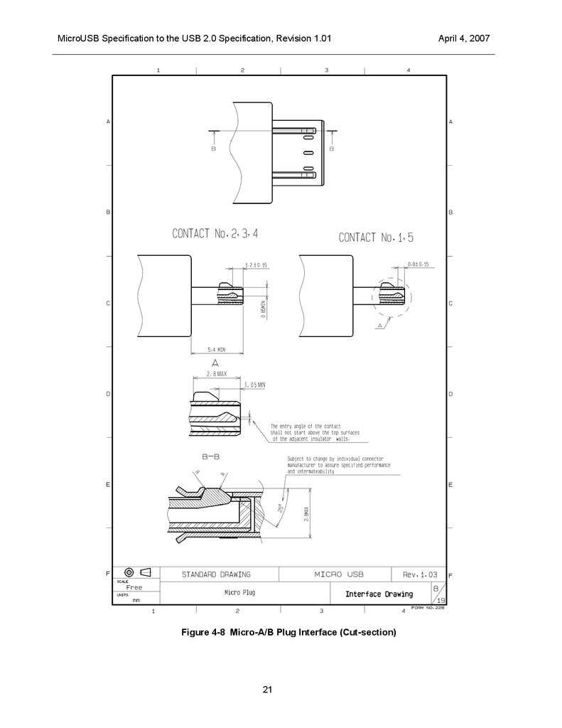
Two pictures edited (Figure 4-8 and 4-9). In fig 4-8 max height to be
2.8mm MAX. In fig 4-9 R0.25mm MAX to be R0.30mm MAX.
For BoD approval
1.0
1/12/2007
Approved
1.0
1/22/2007
Cosmetic edits for publication
1.01
4/4/2007
Editorial corrections and additions to contributor list. Reinserted shell
and plug material requirements as section 6.10. Clarified wording on
Plating Recommendations.
Copyright © 2007 USB Implementers Forum, Inc. (USB-IF).
All rights reserved.
A LICENSE IS HEREBY GRANTED TO REPRODUCE THIS SPECIFICATION FOR INTERNAL USE
ONLY. NO OTHER LICENSE, EXPRESS OR IMPLIED, BY ESTOPPEL OR OTHERWISE, IS
GRANTED OR INTENDED HEREBY.
USB-IF AND THE AUTHORS OF THIS SPECIFICATION EXPRESSLY DISCLAIM ALL LIABILITY
FOR INFRINGEMENT OF INTELLECTUAL PROPERTY RIGHTS, RELATING TO IMPLEMENTATION
OF INFORMATION IN THIS SPECIFICATION. USB-IF AND THE AUTHORS OF THIS
SPECIFICATION ALSO DO NOT WARRANT OR REPRESENT THATSUCH IMPLEMENTATION(S)
WILL NOT INFRINGE THE INTELLECTUAL PROPERTY RIGHTS OF OTHERS.
THIS SPECIFICATION IS PROVIDED "AS IS" AND WITH NO WARRANTIES, EXPRESS OR
IMPLIED, STATUTORY OR OTHERWISE. ALL WARRANTIES ARE EXPRESSLY DISCLAIMED. NO
WARRANTY OF MERCHANTABILITY, NO WARRANTY OF NON-INFRINGEMENT, NO WARRANTY
OF FITNESS FOR ANY PARTICULAR PURPOSE, AND NOWARRANTY ARISING OUT OF ANY
PROPOSAL, SPECIFICATION, OR SAMPLE.
IN NO EVENT WILL USB-IF OR USB-IF MEMBERS BE LIABLE TO ANOTHER FOR THE COST OF
PROCURING SUBSTITUTE GOODS OR SERVICES, LOST PROFITS, LOSS OF USE, LOSS OF
DATA OR ANY INCIDENTAL, CONSEQUENTIAL, INDIRECT, ORSPECIAL DAMAGES, WHETHER
UNDER CONTRACT, TORT, WARRANTY, OR OTHERWISE, ARISING IN ANY WAY OUT OF THE
USE OF THIS SPECIFICATION, WHETHER OR NOT SUCHPARTY HAD ADVANCE NOTICE OF THE
POSSIBILITY OF SUCH DAMAGES.
All product names are trademarks, registered trademarks, or service marks of their respective owners.
2
3.
MicroUSB Specification to the USB 2.0 Specification, Revision 1.01April 4, 2007
Contributors
Mark Rodda, (editor) Motorola
Jan Fahllund, (editor) Nokia
Jim Koser, (CCWG Chairman), Foxconn
Glen Chandler, Advanced-Connectek (Acon)
Charles Wang, Advanced-Connectek (Acon)
Toshinori Sasaki, Across Techno
Minoru Ohara, Allion
Brad Brown, ATL
Christopher Mattson, ATL
Marcus Darrington, ATL
Jaremy Flake, ATL Technology
George Olear, Contech Research
Roy Ting, Elka
Sophia Liu, ETC
Bill Northey, FCI
Tsuneki Watanabe, Foxconn
Jim Zhao, Foxconn
David Ko, Foxconn
Jong Tseng, Foxconn
Jack Lu, Foxlink
Tim Chang, Foxlink
Sathid Inthon, Fujikura
Toshi Mimura, Fujijura
Alan Berkema, Hewlett-Packard
Karl Kwiat, Hirose
Shinya Tono, Hirose
Kazu Ichikawa, Hirose
Ryozo Koyama, Hirose
Yousuke Takeuchi, Hirose
Tsuyoshi Kitagawa, Hosiden
Jim Eilers, Hosiden
Kazuhiro Saito, JAE
Ron Muir, JAE
Mark Saubert, JAE
Yasuhira Miya, JST
Takahiro Diguchi, JST
Yoichi Nakazawa, JST
Kevin Fang, Longwell Electronics
Morgan Jair, Main Super Co.
Tom Kawaguchi, Matsushita Electric Works
Ron Ward, Matsushita Electric Works
Satoshi Yamamoto, Matsushita Electric Works
Yasuhiko Shinohara, Mitsumi
Atsushi Nishio, Mitsumi
Hitoshi Kawamura, Mitsumi
Scott Sommers, Molex
Kevin Delaney, Molex
Kieran Wright, Molex
Padraig McDaid, Molex
Mikko Poikselka, Molex
Sam Liu, Newnex Technology Corp.
Richard Petrie, Nokia
Kai Silvennoinen, Nokia
Panu Ylihaavisto, Nokia
Arthur Zarnowitz, Palm
Douglas Riemer, SMK
Eric Yagi, SMK
Abid Hussain, Summit Microelectronics
Kaz Osada, Tyco
Masaru Ueno, Tyco
Yoshikazu Hirata, Tyco
Ed Beeman, USB Implementers Forum
Mark Paxson, USB Implementers Forum
3
4.
MicroUSB Specification to the USB 2.0 Specification, Revision 1.01April 4, 2007
Table of Contents
1
Introduction................................................................................................................................................6
1.1 General...............................................................................................................................................6
1.2 Objective of the Specification .............................................................................................................6
1.3 Intended Audience/Scope ..................................................................................................................6
1.4 Related Documents............................................................................................................................6
2
Acronyms and Terms................................................................................................................................7
3
Significant Features ..................................................................................................................................8
3.1 USB 2.0 Specification Compliance ....................................................................................................8
3.2 On-The-Go Device .............................................................................................................................8
3.3 Connectors .........................................................................................................................................8
3.4 Compliant Cable Assemblies .............................................................................................................8
3.5 Plug Overmolds ..................................................................................................................................9
4
Cables and Connectors ..........................................................................................................................10
4.1 Introduction.......................................................................................................................................10
4.2 Micro-Connector Mating ...................................................................................................................10
4.3 Color Coding.....................................................................................................................................11
4.4 Device, Cable and Adapter Delays ..................................................................................................11
4.5 Compliant Usage of Connectors and Cables ...................................................................................12
4.5.1 Cables.................................................................................................................................12
4.5.2 Overmolds...........................................................................................................................12
4.5.3 Mechanical Interfaces.........................................................................................................12
4.5.4 Surface mount standard version drawings .........................................................................12
4.5.5 DIP-type and Midmount-type receptacles ..........................................................................12
4.5.6 Connector Keying ...............................................................................................................12
4.5.7 Right Angle Plugs ...............................................................................................................12
4.5.8 Adapters..............................................................................................................................13
4.6 Drawings...........................................................................................................................................13
5
Electrical Compliance Requirements ....................................................................................................33
5.1 Data Rates Beyond USB 2.0 (480Mb/s -->).....................................................................................33
5.2 Low Level Contact Resistance .........................................................................................................33
5.3 Contact Current Rating.....................................................................................................................33
5.3.1 Signal Contacts Only (2, 3, and 4)......................................................................................33
5.3.2 With Power Applied Contacts (1 and 5)..............................................................................33
6
Mechanical Compliance Requirements.................................................................................................34
6.1 Operating Temperature Range ........................................................................................................34
6.1.1 Option I ...............................................................................................................................34
6.1.2 Option II ..............................................................................................................................34
6.2 Insertion Force..................................................................................................................................34
6.3 Extraction Force ...............................................................................................................................34
6.4 Plating...............................................................................................................................................34
6.4.1 Option I ...............................................................................................................................35
6.4.2 Option II ..............................................................................................................................35
6.5 Solderability ......................................................................................................................................35
6.6 Peel Strength (Reference Only) .......................................................................................................35
6.7 Wrenching Strength (Reference Only) .............................................................................................35
6.8 Lead Co-Planarity.............................................................................................................................35
6.9 RoHS Compliance ............................................................................................................................36
6.10 Shell & Latch Materials.....................................................................................................................36
4
5.
MicroUSB Specification to the USB 2.0 Specification, Revision 1.01April 4, 2007
Figures
Figure 4-1 Micro-A to Micro-B Cable ..............................................................................................................14
Figure 4-2 Standard-A to Micro-B Cable .........................................................................................................15
Figure 4-3 Micro-A to Captive Cable...............................................................................................................16
Figure 4-4 Micro-A Plug Overmold, Straight...................................................................................................17
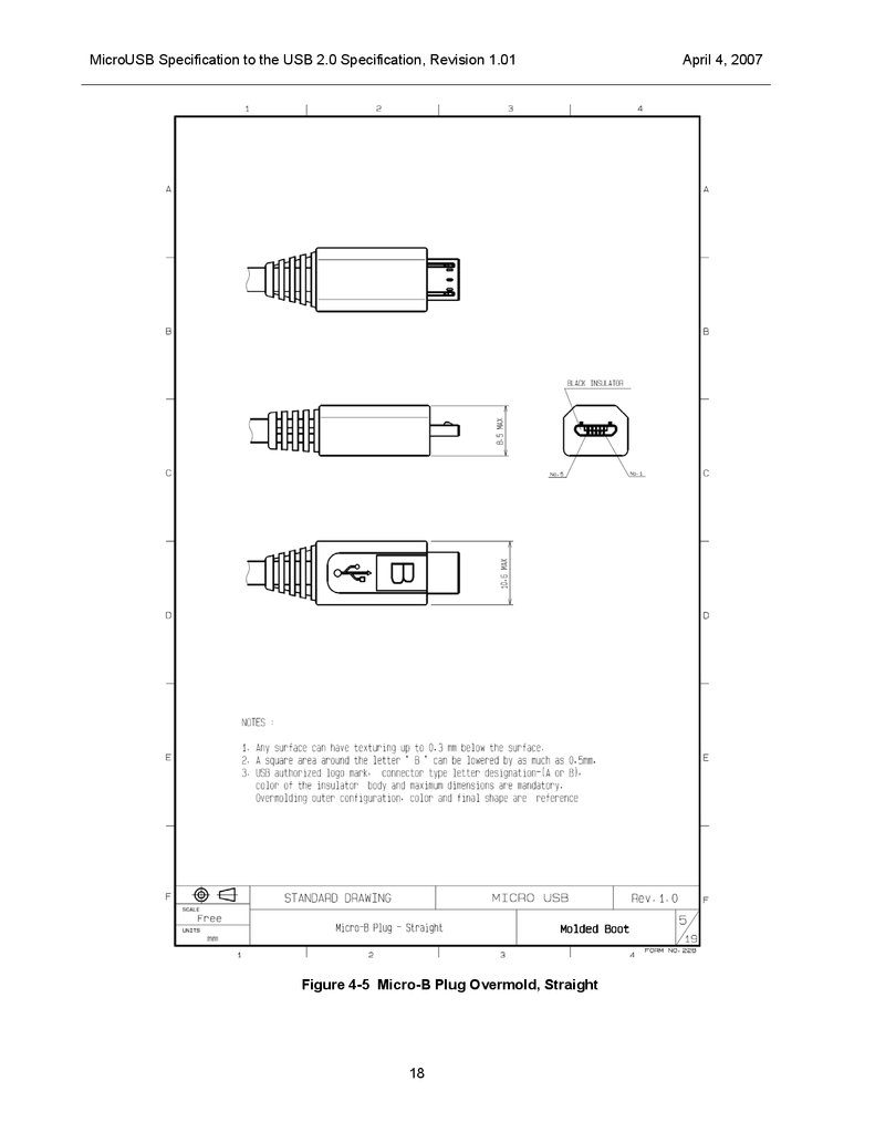
Figure 4-5 Micro-B Plug Overmold, Straight...................................................................................................18
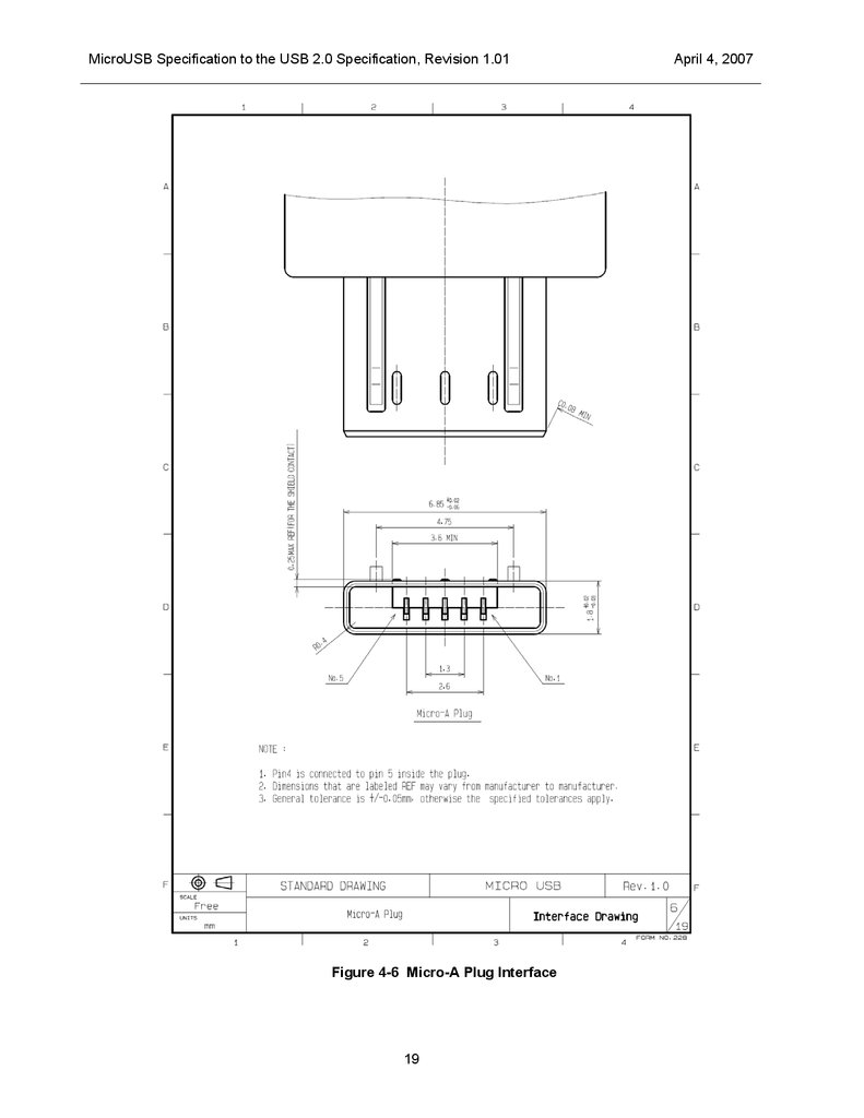
Figure 4-6 Micro-A Plug Interface ...................................................................................................................19
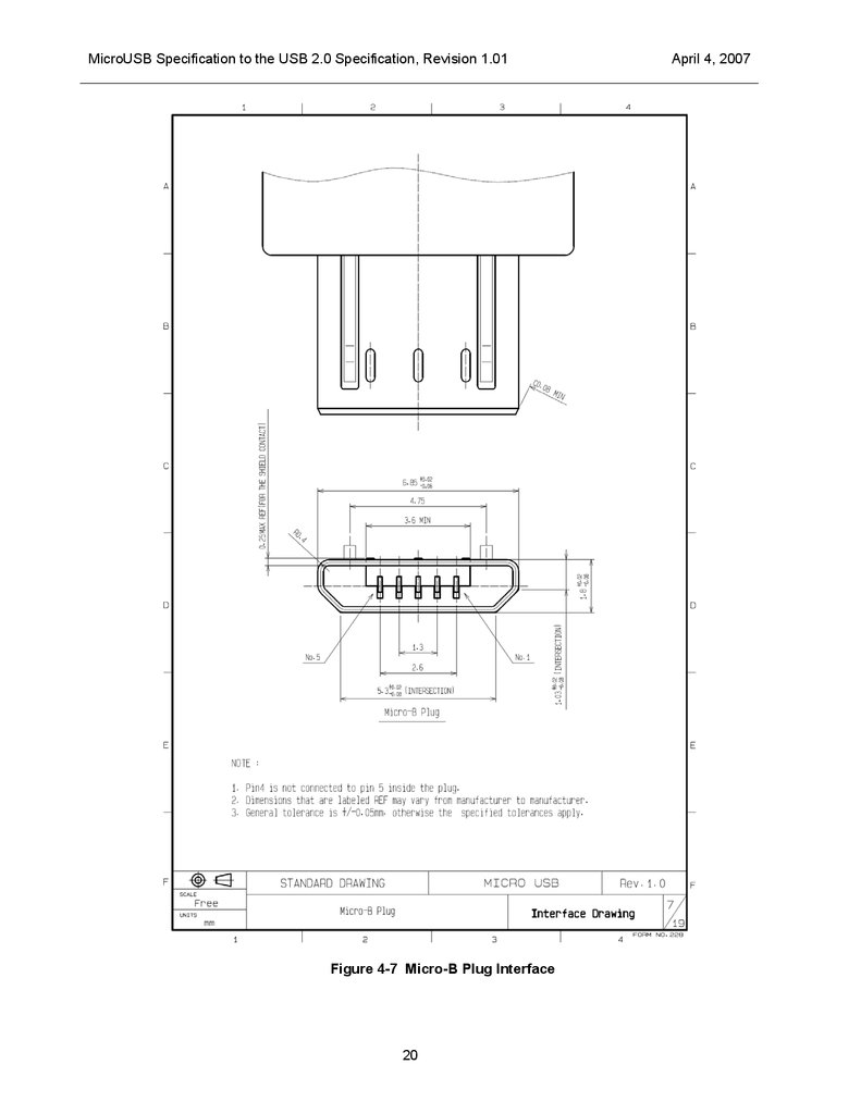
Figure 4-7 Micro-B Plug Interface ...................................................................................................................20
Figure 4-8 Micro-A/B Plug Interface (Cut-section)..........................................................................................21
Figure 4-9 Micro-AB receptacle interface ........................................................................................................22
Figure 4-10 Micro-B receptacle interface........................................................................................................23
Figure 4-11 Micro-AB Receptacle Design ......................................................................................................24
Figure4-12 Micro-B Receptacle Design..........................................................................................................25
Figure 4-13 Micro-A Plug Blockage ................................................................................................................26
Figure 4-14 Micro-B Plug Blockage ................................................................................................................27
Figure 4-15 Micro-A Plug, Side Right Angle ...................................................................................................28
Figure 4-16 Micro-A Plug, Down Right Angle .................................................................................................29
Figure 4-17 Micro-B Plug, Side Right Angle ...................................................................................................30
Figure 4-18 Micro-B Plug, Down Right Angle .................................................................................................31
Figure 4-19 Adapter, Standard-A receptacle to Micro-A plug.........................................................................32
Tables
Table 4-1.
Table 4-2.
Table 4-3.
Table 4-4.
Table 4-5.
Plugs Accepted By Receptacles....................................................................................................10
Micro-A Plug Pin Assignments ......................................................................................................10
Color Coding for Plugs and Receptacles ......................................................................................11
Maximum Delay for Micro-Connector and Cable ..........................................................................11
Maximum Delay for Standard Connector Cable............................................................................11
5
6.
MicroUSB Specification to the USB 2.0 Specification, Revision 1.01April 4, 2007
1 Introduction
1.1
General
USB has become a popular interface for exchanging data between cell phone and portable devices. Many
of these devices have become so small it is impossible to use standard USB components as defined in the
USB 2.0 specification. In addition the durability requirements of the Cell Phone and Portable Devices
market exceed the specifications of the current interconnects. Since Cell Phones and other small Portable
Devices are the largest market potential for USB, this specification is addressing this very large market
while meeting all the requirements for electrical performance within the USB 2.0 specification.
1.2
Objective of the Specification
The purpose of this document is to define the requirements and features of a Micro-USB connector that will
meet the current and future needs of the Cell Phone and Portable Devices markets, while conforming to the
USB 2.0 specification for performance, physical size and shape of the Micro-USB interconnect.
This is not a stand-alone document. Any aspects of USB that are not specifically changed by this
specification are governed by the USB 2.0 Specification and USB On-The-Go Supplement.
1.3
Intended Audience/Scope
Cell phone and Portable Devices have become so thin that the current Mini-USB does not fit well within the
constraints of future designs. Additional requirements for a more rugged connector that will have durability
past 10,000 cycles and still meet the USB 2.0 specification for mechanical and electrical performance was
also a consideration. The Mini-USB could not be modified and remain backward compatible to the existing
connector as defined in the USB OTG specification.
1.4
Related Documents
USB 2.0
USB OTG Supplement
6
7.
MicroUSB Specification to the USB 2.0 Specification, Revision 1.01April 4, 2007
2 Acronyms and Terms
This chapter lists and defines terms and abbreviations used throughout this specification.
A-Device
A device with a Type-A plug inserted into its receptacle. The A-device
supplies power to VBUS and is host at the start of a session. If the Adevice is On-The-Go, it may relinquish the role of host to an On-The-Go
B-device under certain conditions,
Application
A generic term referring to any software that is running on a device that
can control the behavior or actions of the USB port(s) on a device.
B-Device
A device with a Type-B plug inserted into its receptacle. The B-device is
a peripheral at the start of a session. If the B-device is OTG, it may be
granted the role of host from an OTG A-device.
DIP-type
A connector with contact and shield solder tails that are soldered through
the printed circuit board
FS
Full Speed (max 12Mb/s)
Higher than HS
(480Mb/s ---> 5 Gb/s)
HS
High Speed (max 480 Mb/s)
Host
A physical entity that is attached to a USB cable and is acting in the role
of the USB host as defined in the USB Specification, Revision 2.0. This
entity initiates all data transactions and provides periodic Start of Frames.
HNP
Host Negotiation Protocol
ID
Identification. Denotes the pin on the Micro connectors that is used to
differentiate a Micro-A plug from a Micro-B plug.
LS
Low Speed (max 1,5 Mb/s)
Midmount-type
A connector that is mounted in a cut-out in the printed circuit board
between the top and bottom surfaces.
OTG
On-The-Go
OTG device
A device with the host and peripheral capabilities
Peripheral
A physical entity that is attached to a USB cable and is currently
operating as a “device” as defined in the USB Specification, Revision 2.0.
The Peripheral responds to low level bus requests from the Host.
PCB
Printed circuit board
USB
Universal Serial Bus
USB-IF
USB Implementers Forum
7
8.
MicroUSB Specification to the USB 2.0 Specification, Revision 1.01April 4, 2007
3 Significant Features
This section identifies the significant features of the Micro-USB specification. The purpose of this section is
not to present all the technical details associated with each major feature, but rather to highlight its
existence. Where appropriate, this section references other parts of the document where further details can
be found.
3.1
USB 2.0 Specification Compliance
Any device with Micro-USB features is first and foremost a USB peripheral that is compliant with the USB
2.0 specification.
3.2
On-The-Go Device
Any OTG Micro-USB device shall conform to the OTG requirements as set forth in the On-The-Go
Supplement to the USB 2.0 Specification.
3.3
Connectors
The USB 2.0 specification defines the following connectors:
Standard-A plug and receptacle,
Standard-B plug and receptacle, and
Mini-B plug and receptacle.
The Micro-USB specification defines the following additional connectors:
Micro-B plug and receptacle
Micro-AB receptacle
Micro-A plug.
The Micro-AB receptacle is only allowed on OTG products. All other uses of the Micro-AB receptacle are
prohibited. The Micro-AB receptacle accepts either a Micro-A plug or a Micro-B plug.
It is recommended that the Micro-AB continue to support HNP as requested and support full functionality as
a peripheral when a Micro-B plug is inserted.
3.4
Compliant Cable Assemblies
The USB 2.0 specification defines the following cables:
Standard-A plug to Standard–B plug,
Standard-A plug to Mini-B plug, and
Captive cable with Standard-A plug.
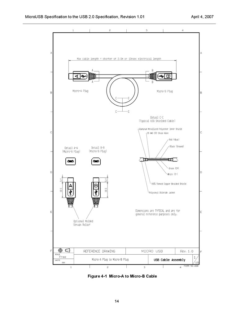
The Micro-USB specification defines the following additional cables:
Micro-A plug to Micro-B plug,
Micro-A plug to Standard-A receptacle
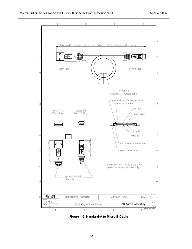
Micro-B plug to Standard-A plug, and
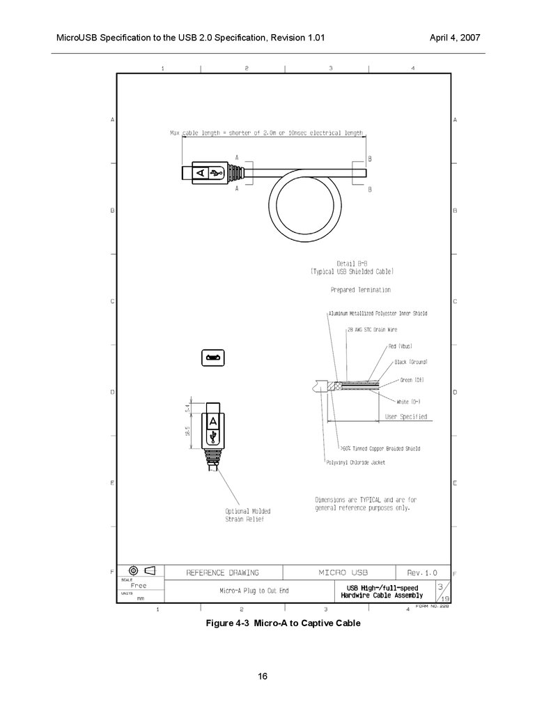
Hardwired Captive cable with Micro-A plug. (Hardwired Captive cable is a cable, connected
internally to a device, which is not designed to be removed by the end user of that device.)
No other types of cables are allowed by either the USB specification, or by the OTG supplement. Cables
are not allowed to have receptacles on either end unless they meet the mechanical and electrical
requirements of adapters defined in this document.
8
9.
MicroUSB Specification to the USB 2.0 Specification, Revision 1.013.5
April 4, 2007
Plug Overmolds
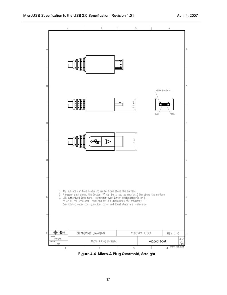
The Micro-USB specification constrains the size and the shape of the overmolds for the Micro-A and
Micro-B plugs.
The Micro-A plug’s overmold has a rectangular shape, and the Micro-B plug’s overmold is rectangular with
chamfers. This allows easy recognition and differentiation of the two plugs by the consumer See pictures
Figure 4-4 and Figure 4-5.
9
10.
MicroUSB Specification to the USB 2.0 Specification, Revision 1.01April 4, 2007
4 Cables and Connectors
4.1
Introduction
This chapter provides the mechanical and electrical specifications for the cables, connectors and cable
assemblies used to interconnect devices as well as constraints on the design of the overmolds for the
Micro-A and Micro-B plugs.
4.2
Micro-Connector Mating
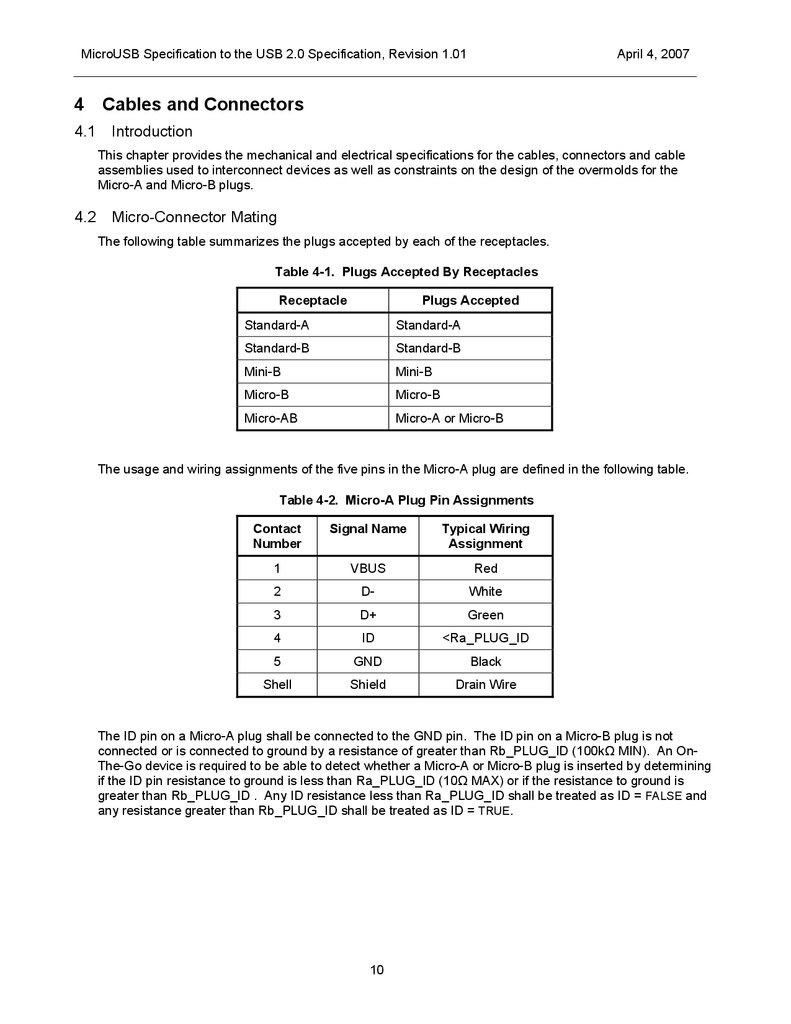
The following table summarizes the plugs accepted by each of the receptacles.
Table 4-1. Plugs Accepted By Receptacles
Receptacle
Plugs Accepted
Standard-A
Standard-A
Standard-B
Standard-B
Mini-B
Mini-B
Micro-B
Micro-B
Micro-AB
Micro-A or Micro-B
The usage and wiring assignments of the five pins in the Micro-A plug are defined in the following table.
Table 4-2. Micro-A Plug Pin Assignments
Contact
Number
Signal Name
Typical Wiring
Assignment
1
VBUS
Red
2
D-
White
3
D+
Green
4
ID
<Ra_PLUG_ID
5
GND
Black
Shell
Shield
Drain Wire
The ID pin on a Micro-A plug shall be connected to the GND pin. The ID pin on a Micro-B plug is not
connected or is connected to ground by a resistance of greater than Rb_PLUG_ID (100kΩ MIN). An OnThe-Go device is required to be able to detect whether a Micro-A or Micro-B plug is inserted by determining
if the ID pin resistance to ground is less than Ra_PLUG_ID (10Ω MAX) or if the resistance to ground is
greater than Rb_PLUG_ID . Any ID resistance less than Ra_PLUG_ID shall be treated as ID = FALSE and
any resistance greater than Rb_PLUG_ID shall be treated as ID = TRUE.
10
11.
MicroUSB Specification to the USB 2.0 Specification, Revision 1.014.3
April 4, 2007
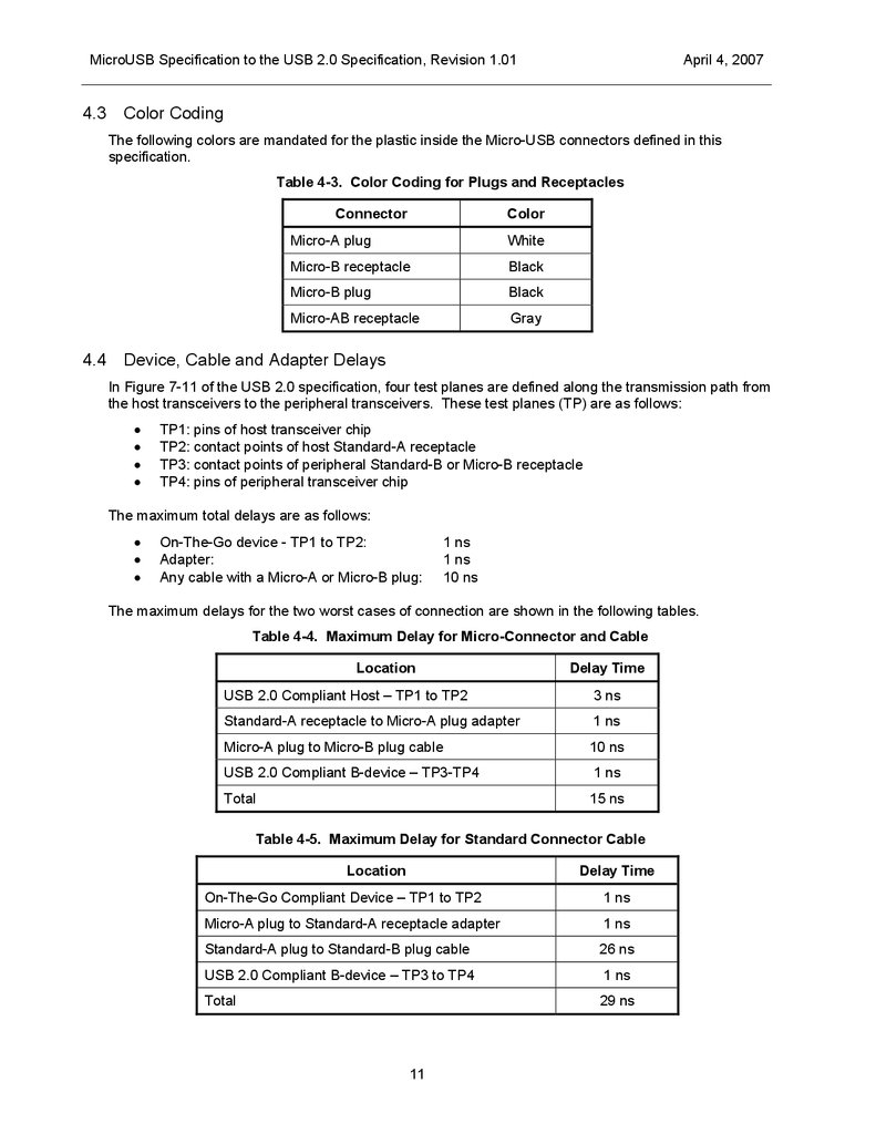
Color Coding
The following colors are mandated for the plastic inside the Micro-USB connectors defined in this
specification.
Table 4-3. Color Coding for Plugs and Receptacles
Connector
4.4
Color
Micro-A plug
White
Micro-B receptacle
Black
Micro-B plug
Black
Micro-AB receptacle
Gray
Device, Cable and Adapter Delays
In Figure 7-11 of the USB 2.0 specification, four test planes are defined along the transmission path from
the host transceivers to the peripheral transceivers. These test planes (TP) are as follows:
TP1: pins of host transceiver chip
TP2: contact points of host Standard-A receptacle
TP3: contact points of peripheral Standard-B or Micro-B receptacle
TP4: pins of peripheral transceiver chip
The maximum total delays are as follows:
On-The-Go device - TP1 to TP2:
Adapter:
Any cable with a Micro-A or Micro-B plug:
1 ns
1 ns
10 ns
The maximum delays for the two worst cases of connection are shown in the following tables.
Table 4-4. Maximum Delay for Micro-Connector and Cable
Location
Delay Time
USB 2.0 Compliant Host – TP1 to TP2
3 ns
Standard-A receptacle to Micro-A plug adapter
1 ns
Micro-A plug to Micro-B plug cable
10 ns
USB 2.0 Compliant B-device – TP3-TP4
1 ns
Total
15 ns
Table 4-5. Maximum Delay for Standard Connector Cable
Location
Delay Time
On-The-Go Compliant Device – TP1 to TP2
1 ns
Micro-A plug to Standard-A receptacle adapter
1 ns
Standard-A plug to Standard-B plug cable
26 ns
USB 2.0 Compliant B-device – TP3 to TP4
1 ns
Total
29 ns
11
12.
MicroUSB Specification to the USB 2.0 Specification, Revision 1.014.5
April 4, 2007
Compliant Usage of Connectors and Cables
Cable assemblies and connectors not described below or not allowed by other amendments to the USB
specification are not compliant with the USB specification and may not be labeled as such.
4.5.1
Cables
The cables allowed by the Micro-USB specification are shown in Figure 4-1, Figure 4-2, and Figure 4-3.
Cables must have a propagation delay of 10 ns or less, have a physical length of no more than 2.0 meters,
and meet all other requirements of a USB cable.
4.5.2
Overmolds
The size and shape of the Micro-A and Micro-B plug overmolds must conform to the constraints shown in
Figure 4-4 and Figure 4-5 .
4.5.3
Mechanical Interfaces
The mechanical interface dimensions for the Micro-A and Micro-B plugs are shown in Figure 4-6 and Figure
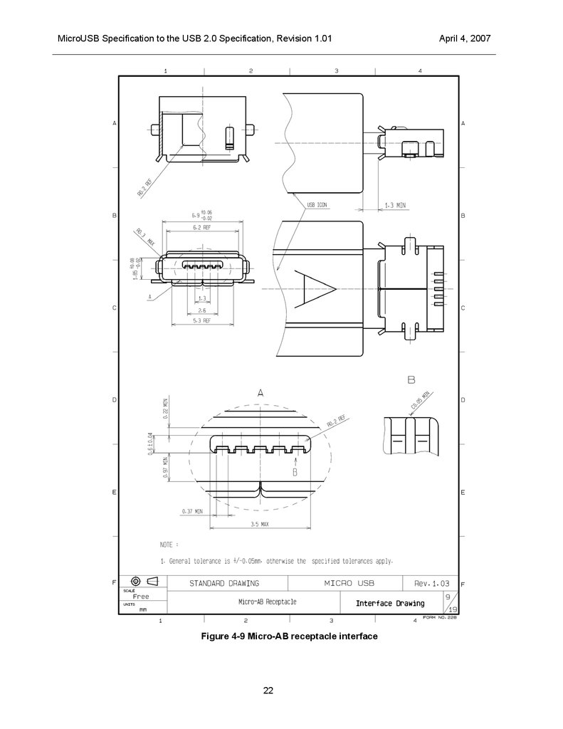
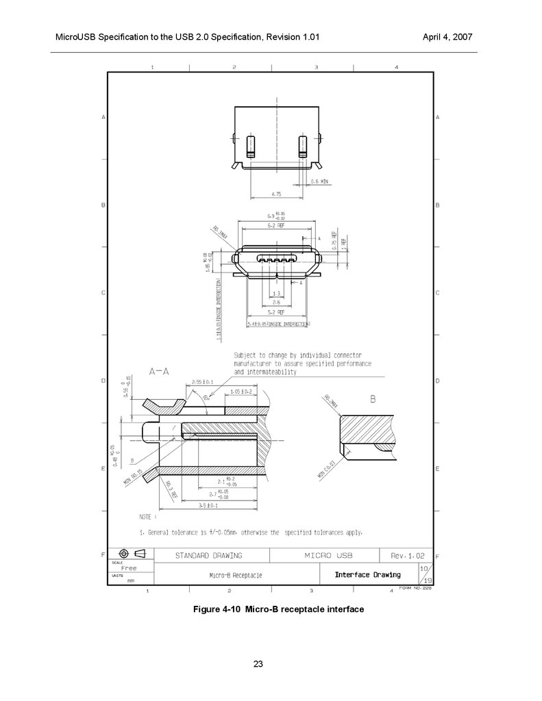
4-7. Mechanical interface dimensions for Micro-AB and Micro-B receptacles are shown in Figure 4-9 and
Figure 4-10.
4.5.4
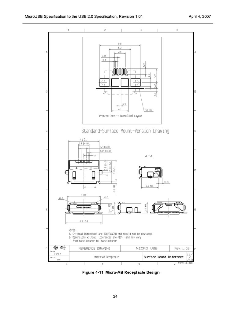
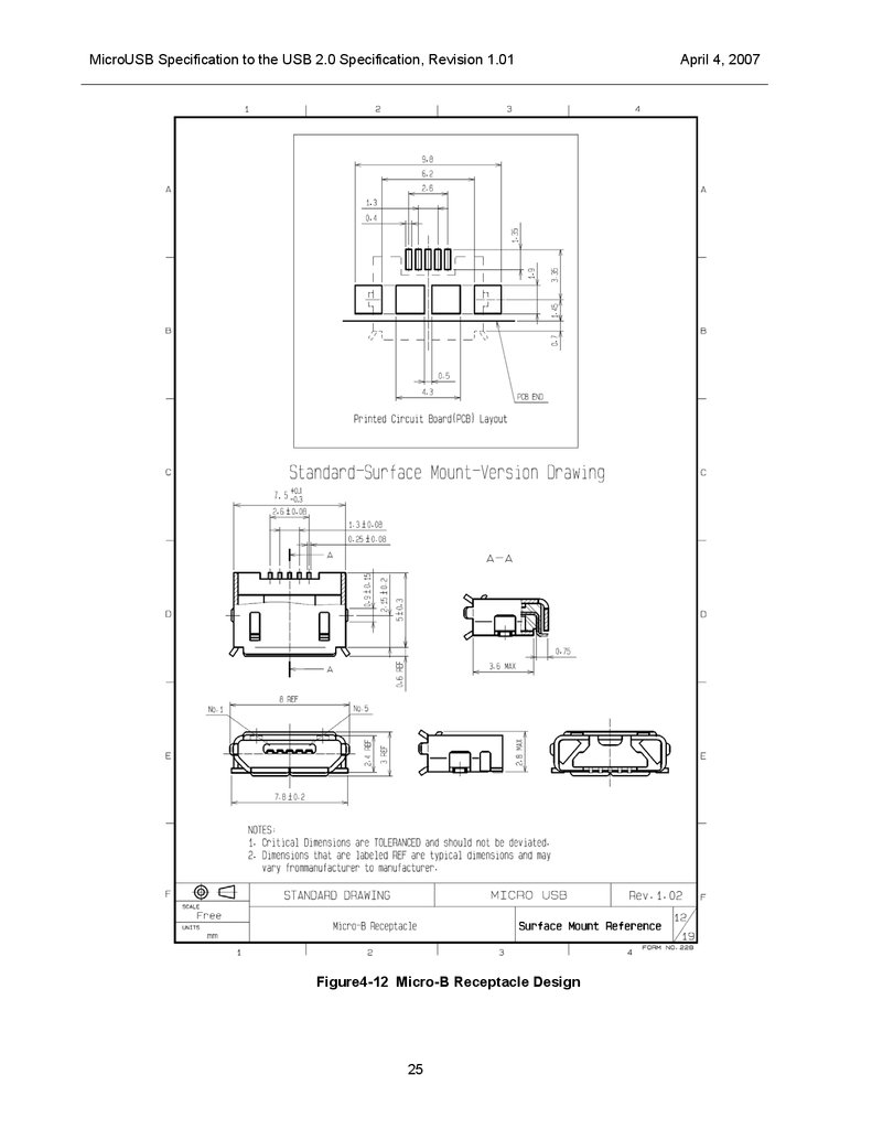
Surface mount standard version drawings
By following these instructions, receptacles from different manufacturers can be used interchangeably on
the same printed circuit board (PCB). In the case of the “surface mount standard version”, the dimensions
of the contact tail and shield tail must comply with figures 4-11 and 4-12.
Note: PCB-layout drawings are included for reference only.
Figure 4-11 and Figure4-12 shows designs for the Micro-AB and Micro-B receptacles respectively.
4.5.5
DIP-type and Midmount-type receptacles
DIP-type (contact and shield tails soldered through PCB) and Midmount-type (connector that is mounted in
a cut-out in the printed circuit board between the top and bottom surfaces.) receptacle connectors are not
defined in this standards document. These mounting styles are allowed under the standard as long as all
intermating conditions are met. Mechanical dimensions and mechanical durability values may vary from the
Surface mount standard connector but must comply with all minimum values.
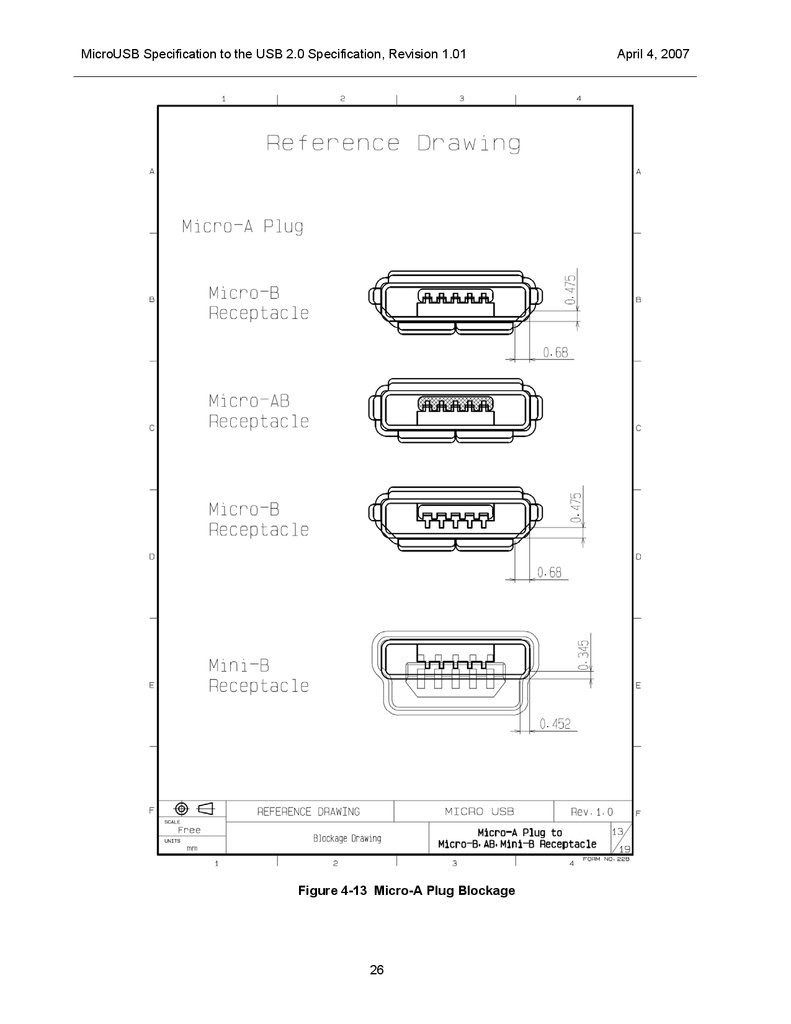
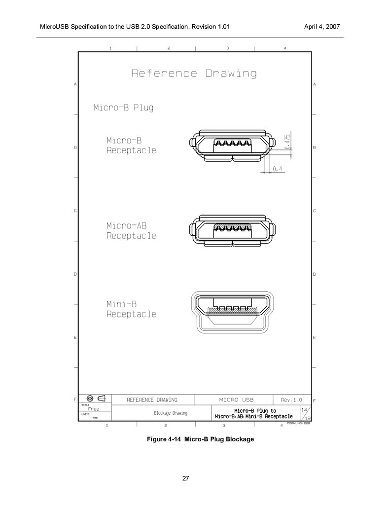
4.5.6
Connector Keying
This Micro connector series has been designed so as to prevent the Micro-A and Micro-B plugs from being
incorrectly inserted into a receptacle. The amount of metal blocking various possible incorrect insertions is
shown in Figure 4-13 and Figure 4-14, and is always greater than 0.35 mm.
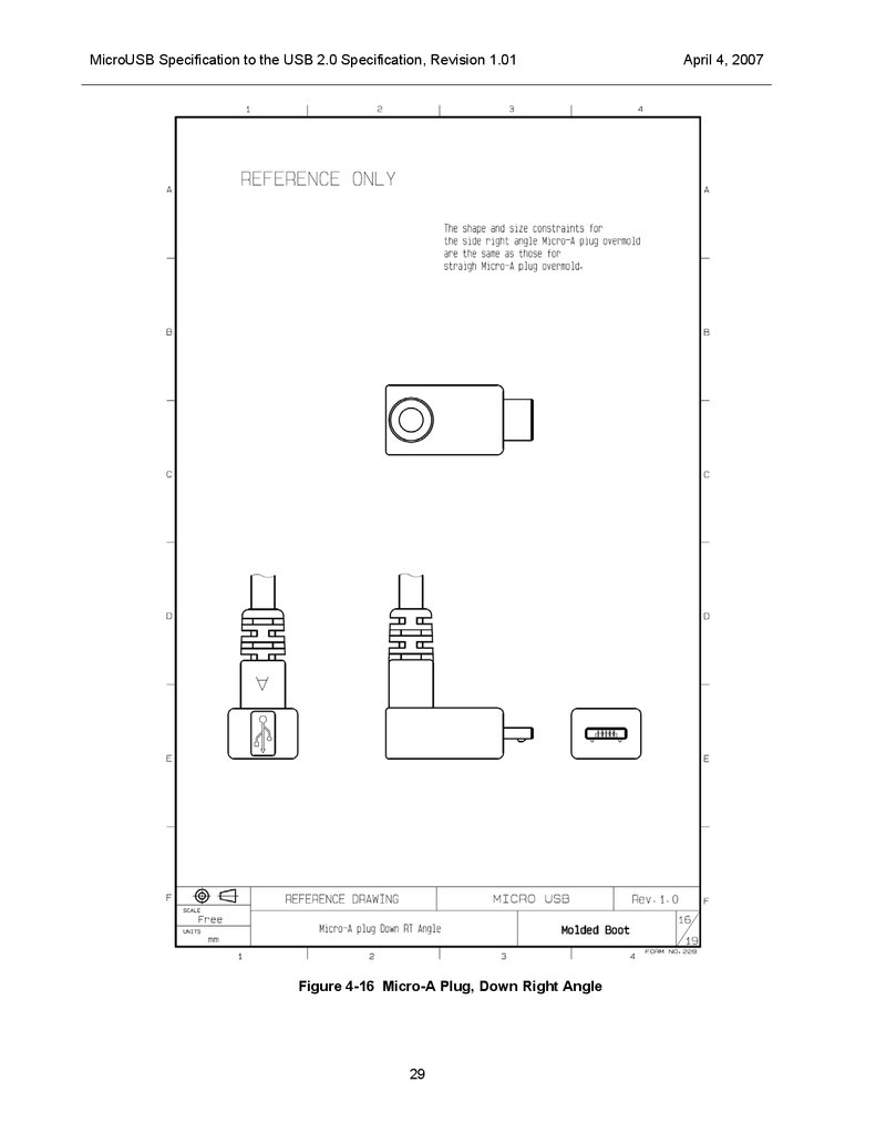
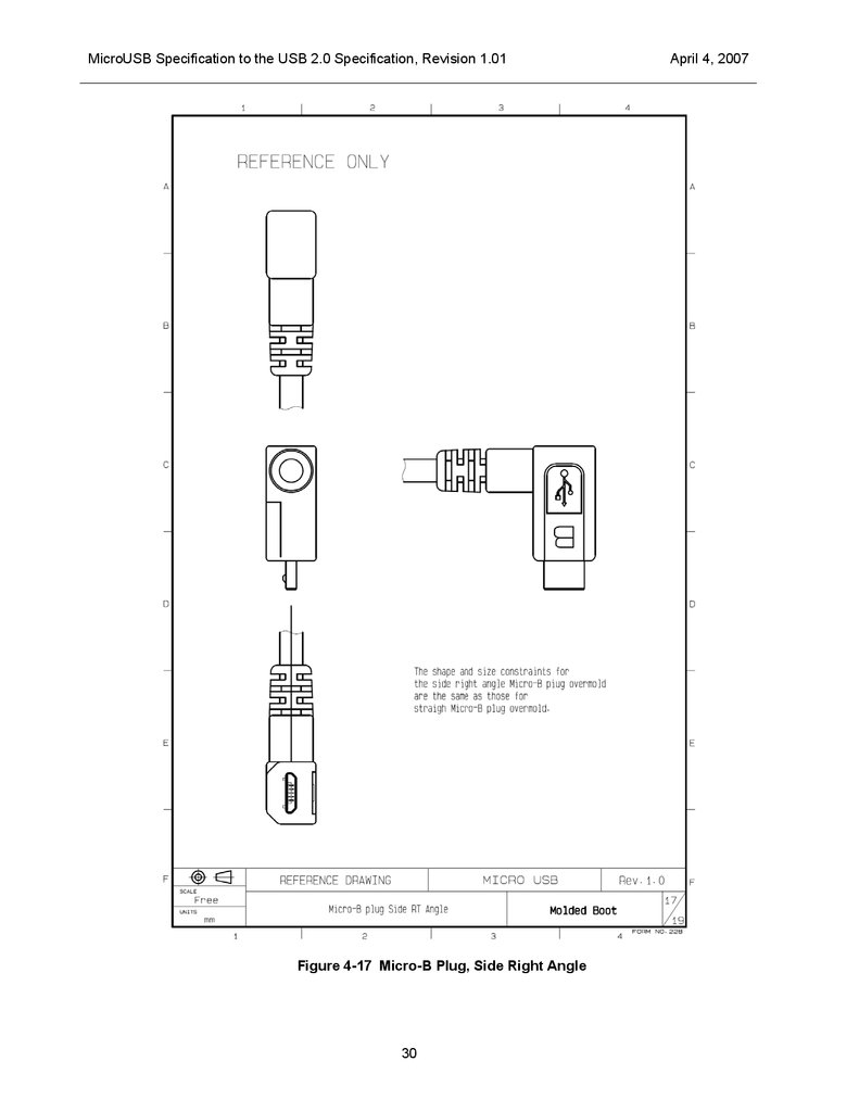
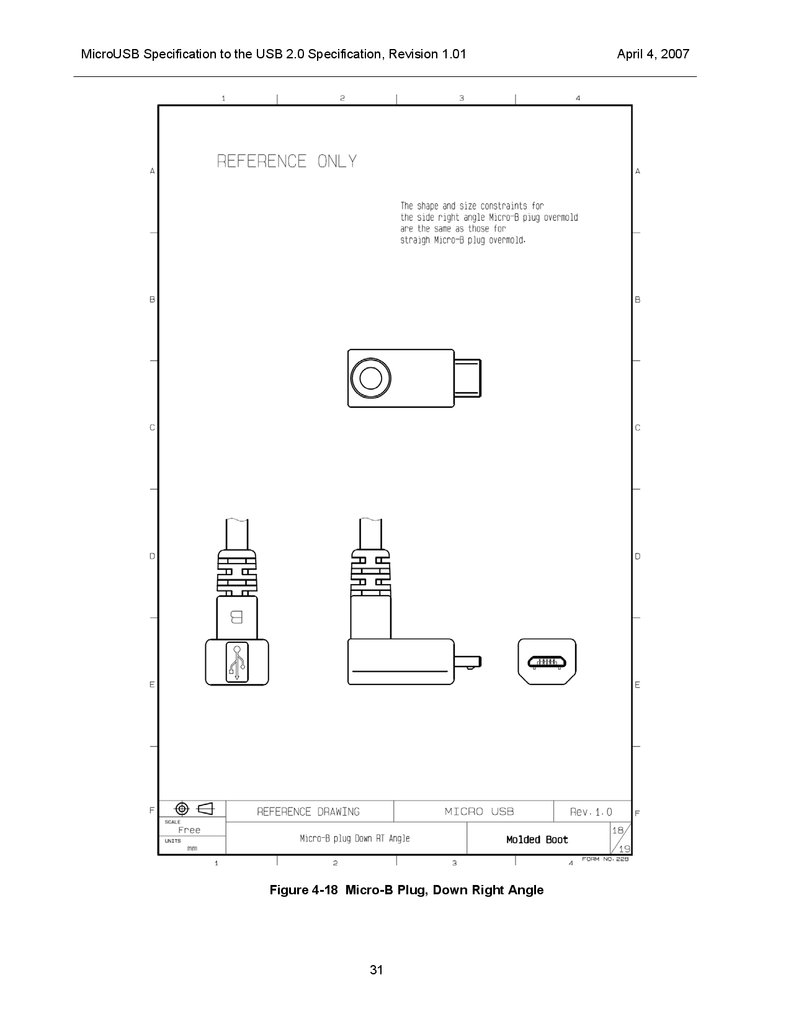
4.5.7
Right Angle Plugs
The overmolds for right / down angle plugs are required to comply with the same shape constraints that
apply to straight plugs. Reference drawings for right / down angle plugs are shown in Figure 4-15, Figure
4-16, Figure 4-17 and Figure 4-18 .
12
13.
MicroUSB Specification to the USB 2.0 Specification, Revision 1.014.5.8
April 4, 2007
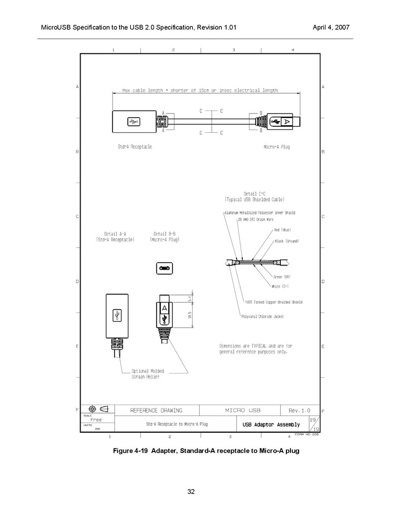
Adapters
Requirements:
4.5.8.1
The propagation delay of the adapter shall be less than 1 ns.
The physical length shall not exceed 150 mm.
The resistance of the adapter through VBUS and GND, including contacts, shall not exceed 70 mΩ.
Standard-A receptacle to Micro-A plug
This adapter is used to connect a cable with a Standard-A plug to an On-The-Go device that has a MicroAB receptacle. A reference drawing for this adapter is shown in Figure 4-19.
4.6
Drawings
This section contains the mechanical drawings that are referenced in the previous section.
13
14.
MicroUSB Specification to the USB 2.0 Specification, Revision 1.01Figure 4-1 Micro-A to Micro-B Cable
14
April 4, 2007
15.
MicroUSB Specification to the USB 2.0 Specification, Revision 1.01Figure 4-2 Standard-A to Micro-B Cable
15
April 4, 2007
16.
MicroUSB Specification to the USB 2.0 Specification, Revision 1.01Figure 4-3 Micro-A to Captive Cable
16
April 4, 2007
17.
MicroUSB Specification to the USB 2.0 Specification, Revision 1.01Figure 4-4 Micro-A Plug Overmold, Straight
17
April 4, 2007
18.
MicroUSB Specification to the USB 2.0 Specification, Revision 1.01Figure 4-5 Micro-B Plug Overmold, Straight
18
April 4, 2007
19.
MicroUSB Specification to the USB 2.0 Specification, Revision 1.01Figure 4-6 Micro-A Plug Interface
19
April 4, 2007
20.
MicroUSB Specification to the USB 2.0 Specification, Revision 1.01Figure 4-7 Micro-B Plug Interface
20
April 4, 2007
21.
MicroUSB Specification to the USB 2.0 Specification, Revision 1.01Figure 4-8 Micro-A/B Plug Interface (Cut-section)
21
April 4, 2007
22.
MicroUSB Specification to the USB 2.0 Specification, Revision 1.01Figure 4-9 Micro-AB receptacle interface
22
April 4, 2007
23.
MicroUSB Specification to the USB 2.0 Specification, Revision 1.01Figure 4-10 Micro-B receptacle interface
23
April 4, 2007
24.
MicroUSB Specification to the USB 2.0 Specification, Revision 1.01Figure 4-11 Micro-AB Receptacle Design
24
April 4, 2007
25.
MicroUSB Specification to the USB 2.0 Specification, Revision 1.01Figure4-12 Micro-B Receptacle Design
25
April 4, 2007
26.
MicroUSB Specification to the USB 2.0 Specification, Revision 1.01Figure 4-13 Micro-A Plug Blockage
26
April 4, 2007
27.
MicroUSB Specification to the USB 2.0 Specification, Revision 1.01Figure 4-14 Micro-B Plug Blockage
27
April 4, 2007
28.
MicroUSB Specification to the USB 2.0 Specification, Revision 1.01Figure 4-15 Micro-A Plug, Side Right Angle
28
April 4, 2007
29.
MicroUSB Specification to the USB 2.0 Specification, Revision 1.01Figure 4-16 Micro-A Plug, Down Right Angle
29
April 4, 2007
30.
MicroUSB Specification to the USB 2.0 Specification, Revision 1.01Figure 4-17 Micro-B Plug, Side Right Angle
30
April 4, 2007
31.
MicroUSB Specification to the USB 2.0 Specification, Revision 1.01Figure 4-18 Micro-B Plug, Down Right Angle
31
April 4, 2007
32.
MicroUSB Specification to the USB 2.0 Specification, Revision 1.01Figure 4-19 Adapter, Standard-A receptacle to Micro-A plug
32
April 4, 2007
33.
MicroUSB Specification to the USB 2.0 Specification, Revision 1.01April 4, 2007
5 Electrical Compliance Requirements
Electrical requirements are unchanged from the USB 2.0 specification (Chapter 6; Table 6-7) and the OnThe-Go Supplement to the USB 2.0 Specification, unless otherwise specified here.
5.1
Data Rates Beyond USB 2.0 (480Mb/s -->)
This section will be amended as requirements for higher data rates (beyond the current USB 2.0
specification) become available.
5.2
Low Level Contact Resistance
30mΩ (Max) initial when measured at 20mV (Max) open circuit at 100mA. Maximum change (delta) of
+10 mΩ after 10,000 insertion/extraction cycles at a maximum rate of 500 cycles per hour. (When manually
operated, mating speed should be below 200 cycles per hour.)
5.3
Contact Current Rating
5.3.1
Signal Contacts Only (2, 3, and 4)
1A minimum when measured at an ambient temperature of 25 degrees Celsius. With power applied to the
contacts, the delta temperature must not exceed +30degrees Celsius at any point in the USB connector
under test.
5.3.2
With Power Applied Contacts (1 and 5)
1.8A for contacts 1 and 5 and at the same time 0.5A for contacts 2, 3 & 4, minimum when measured at an
ambient temperature of 25 degrees Celsius. With power applied to the contacts, the delta temperature must
not exceed +30degrees Celsius at any point in the USB connector under test.
33
34.
MicroUSB Specification to the USB 2.0 Specification, Revision 1.01April 4, 2007
6 Mechanical Compliance Requirements
The following requirements will take precedence over the requirements set forth in the USB 2.0
specification (Chapter 6; Table 6-8) and the On-The-Go Supplement to the USB 2.0 Specification.
6.1
Operating Temperature Range
6.1.1
Option I
-30°C to +80°C
6.1.2
Option II
-30°C to +85°C (and above)
6.2
Insertion Force
Recommendations:
6.3
6.4
-
It is recommend to use a non-silicon based lubricant on the latching mechanism to
reduce wear. If used the lubricant may not affect any other characteristic of the system.
-
35 Newton’s maximum at a maximum rate of 12.5 mm(0.492") per minute.
Extraction Force
-
8N (MIN) after 10000 insertion/extraction cycles (at a maximum rate of 12.5mm
(0.492") per minute).
-
No burs or sharp edges are allowed on top of locking latches (hook surfaces which will
rub against receptacle shield).
-
It is recommend to use a non-silicon based lubricant on the latching mechanism to
reduce wear. If used the lubricant may not affect any other characteristic of the system.
Plating
Recommendations:
-
Contact plating should be done after stamping and forming
-
Burrs should not be present on contact areas
-
Contact area as smooth as possible before plating
-
Use a sealing treatment to control plating porosity (contact area)
34
35.
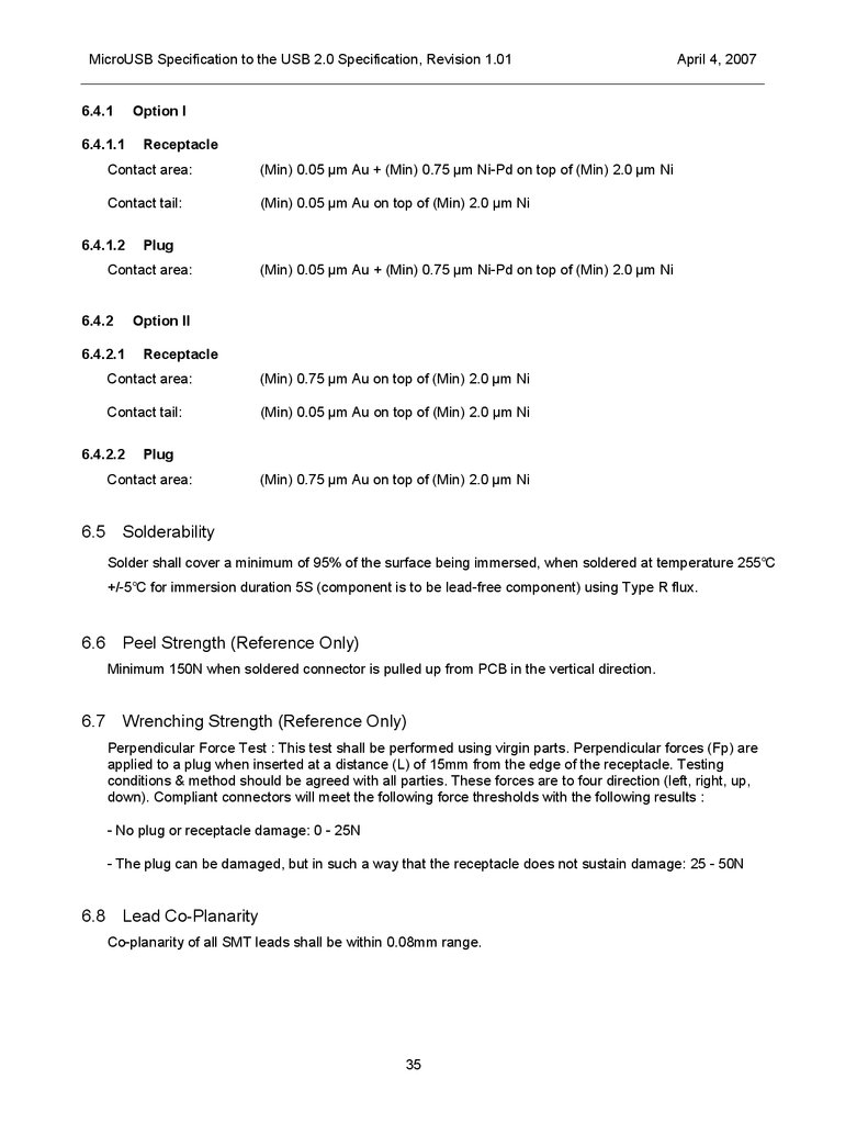
MicroUSB Specification to the USB 2.0 Specification, Revision 1.016.4.1
Option I
6.4.1.1
Receptacle
Contact area:
(Min) 0.05 µm Au + (Min) 0.75 µm Ni-Pd on top of (Min) 2.0 µm Ni
Contact tail:
(Min) 0.05 µm Au on top of (Min) 2.0 µm Ni
6.4.1.2
Plug
Contact area:
6.4.2
(Min) 0.05 µm Au + (Min) 0.75 µm Ni-Pd on top of (Min) 2.0 µm Ni
Option II
6.4.2.1
Receptacle
Contact area:
(Min) 0.75 µm Au on top of (Min) 2.0 µm Ni
Contact tail:
(Min) 0.05 µm Au on top of (Min) 2.0 µm Ni
6.4.2.2
Plug
Contact area:
6.5
April 4, 2007
(Min) 0.75 µm Au on top of (Min) 2.0 µm Ni
Solderability
Solder shall cover a minimum of 95% of the surface being immersed, when soldered at temperature 255℃
+/-5℃ for immersion duration 5S (component is to be lead-free component) using Type R flux.
6.6
Peel Strength (Reference Only)
Minimum 150N when soldered connector is pulled up from PCB in the vertical direction.
6.7
Wrenching Strength (Reference Only)
Perpendicular Force Test : This test shall be performed using virgin parts. Perpendicular forces (Fp) are
applied to a plug when inserted at a distance (L) of 15mm from the edge of the receptacle. Testing
conditions & method should be agreed with all parties. These forces are to four direction (left, right, up,
down). Compliant connectors will meet the following force thresholds with the following results :
- No plug or receptacle damage: 0 - 25N
- The plug can be damaged, but in such a way that the receptacle does not sustain damage: 25 - 50N
6.8
Lead Co-Planarity
Co-planarity of all SMT leads shall be within 0.08mm range.
35
36.
MicroUSB Specification to the USB 2.0 Specification, Revision 1.016.9
April 4, 2007
RoHS Compliance
Component is to be RoHS compliant. Lead Free plug and receptacle materials must conform to Directive
2002/95/EC of January 27, 2003 on Restriction of Hazardous Substances (RoHS).
6.10 Shell & Latch Materials
Shell and latch materials for both plug and receptacle shall be stainless steel or mechanically equivalent
material.
36