


 marketing
 electronics
Similar presentations:


"Gocuz". Catalogue
1.
“We create better life with Light.”GOC pursues satisfaction of customers with value of creation
and keeps challenging with spirit relying on human respect.
We manufacture indoor & outdoor optical fiber cable of IT industries.
We endeavor to develop technology to be competitive in the future.
We promise to be the best partner at the fiber optical business field.
CEO Mr. In-Chul Park
Indoor Cord & Cable +3
2.
OOPPTTICCAALLFFIBBEERRCCAABBLLEESSCCOONNTTEENNTTSS
Indoor Outdoor Cable
5. Furcation Tube
6.Tight BufferedFiber 0
7 Optical Cord Cable 0
8 4C Zip Cord
09 Flat Cable
10 Ribbon Cord Cable
11 Ribbon Cord Cable (DoubleJacket)
12 Distribution Optical Cable
13 Distribution Cable
14 Fig-8 Distribution Cable
15 Distribution Cable (DuctType)
16 Armored Distribution Cable (AerialType)
17 Breakout Cable
Loose TubeCable
18 Duct Loose Tube Cable (SJSA)
19 Duct Loose Tube Cable (Non-metallic)
20 Flame Retardant Duct Loose TubeCable
21 ADSS Cable (Single Jacket)
22 ADSS Cable (Double Jacket)
23 Anti-Rodent ADSS Cable
24 Fig-8 Loose Tube Cable (Non-metallic)
25 Aerial Loose TubeCable
26 Distribution Loose tube Cable (Fig-8Type)
27 Distribution Loose tube Cable (DuctType)
28 Direct Buried Loose TubeCable
29 Central Loose TubeCable
30 Flat Central Loose TubeCable
31 Armored Central Loose TubeCable
32 PIMC Micro-duct Tube
33 PIMC (Pulling Installation Micro Duct LooseCable)
Micro SheathCable
34 Dry Core Micro SheathCable
35 Micro Sheath Cable (DistributionType)
36 Micro Sheath Cable (BreakoutType)
37 Fig-8 Micro SheathCable
SpecialCable
38 Nuclear RR Indoor Fiber OpticCable
39 Nuclear RR Loose Fiber OpticCable
40 Steel Armored Optical Cable
4 + GOC Co., Ltd.
41
42
43
44
45
46
47
48
49
50
51
Steel Armored Cable (Double Sheath)
Steel Armored Duplex Cord
Dry Core Optical Cable
Specialty Optical Patch Cord
Military Tactical Optical Cable
Emergency Repairing Optical Cable
Hybrid Cable
Hybrid Cable (3C Copper + 4C OpticalFiber)
Hybrid Cable 1 RRU
Hybrid Cable 3 RRU
Hybrid POF Fig-8 Type Distribution Cable
FTTx Cable
52 FTTH Optical Cable (BufferType)
53 FTTX Drop Cable (FiberType)
54 FTTX Distribution Cable (DoubleSheath)
55 FTTH Indoor Drop Cable (RectangleType)
56 FTTH Outdoor Drop Cable (RectangleType)
57 Fig-8 Type Optical Cable
58 Air Blown Fiber
59 ABMC (Air Blown Micro Cable)
60 Micro Trenching Cable
61 Buffer type Central loose tubecable
62 FTTH Transparent Strong Buffer &Rail
FTTHType
Fig-8Dry
Mini
DistributionCable
63
63 Buffer
Core
Drop Cable
Fiber
Type
Mini
Drop
Cable
64
64 Buffer Type Mini Drop Cable
FTTxFig-8
Pre-Connectorized
Patch
cord
65 FTTH
Mini Distribution
Cable
65
66 Fiber Type Mini Drop Cable
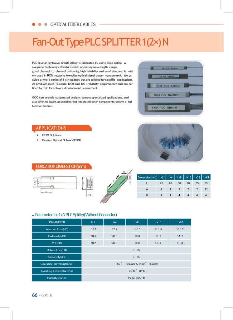
67 FTTx PLCSplitter
Pre-Connectorized Patch cord
Optical
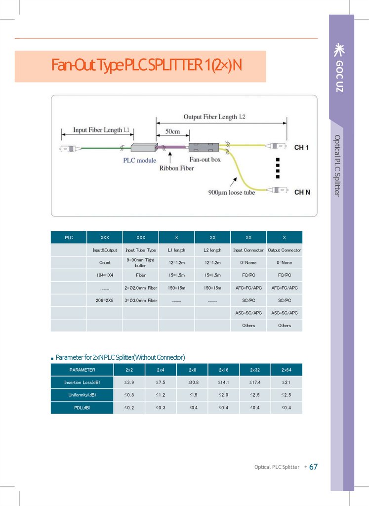
Fan-Out
Type PLC Splitter 1(2) X N 48,49
66
Integrated
Type PLC Splitter 1 X N
68
Optical
PLC Splitter
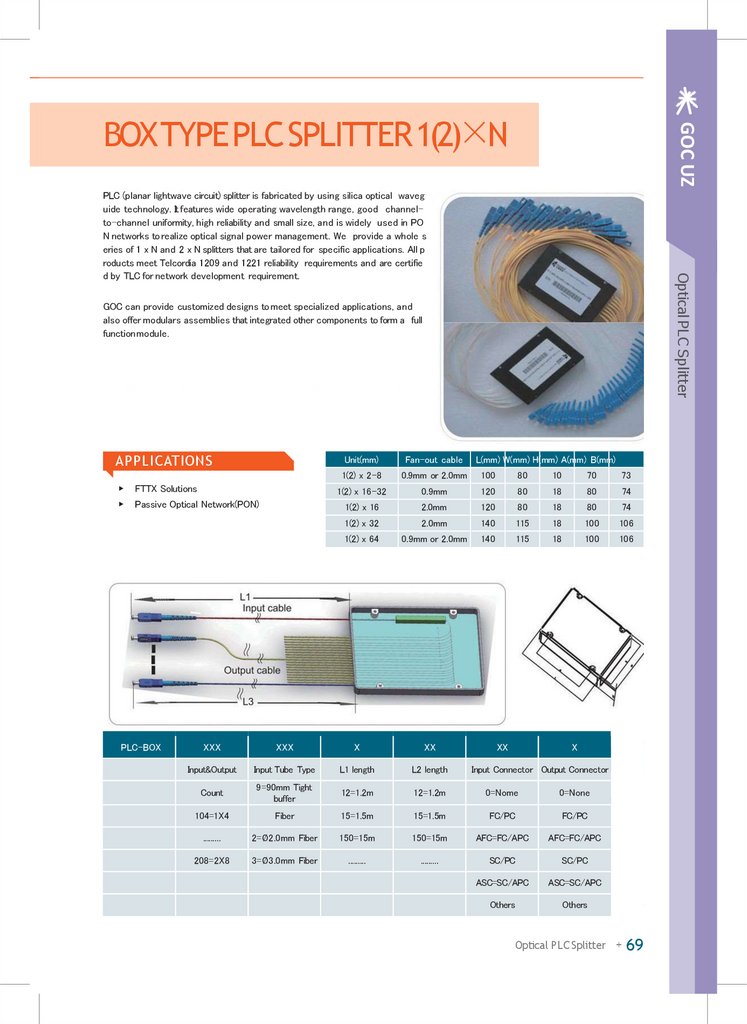
Box Type
PLC
Splitter
1(2)1(2)
X NX N 48, 49
68 Fan-Out
Type
PLC
Splitter
69
70 Integrated Type PLC Splitter 1 X N
71 Box Type PLC Splitter 1(2) X N
Accessory
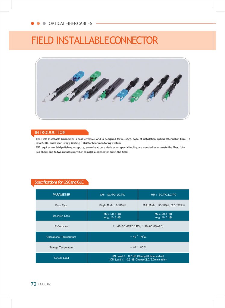
70 Field InstallableConnector
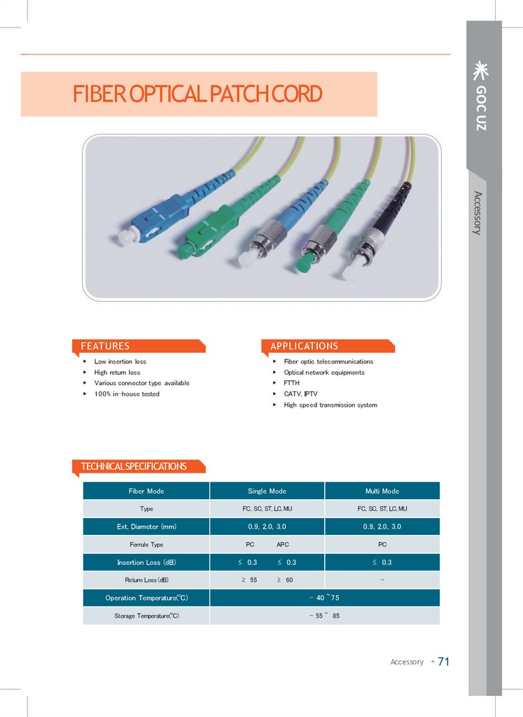
Fiber Optic Patch Cord Ac
71
Accessory
cessInstallable
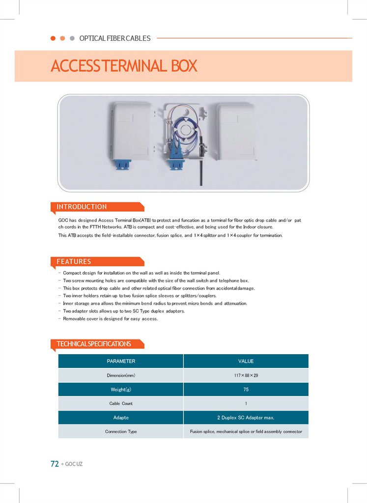
Terminal Box
72 Field
Connector
72
Aerial
TYPE
Joint
closure(Ventilationtype)
73 Fiber
Optic
Patch
Cord
Aerial Type
Fiber
Optic TerminalBox
Terminal
Box
74 Access
Pole
Type
Fiber
Optic
Distribution Box
type)
75 Aerial TYPE Joint closure(Ventilation
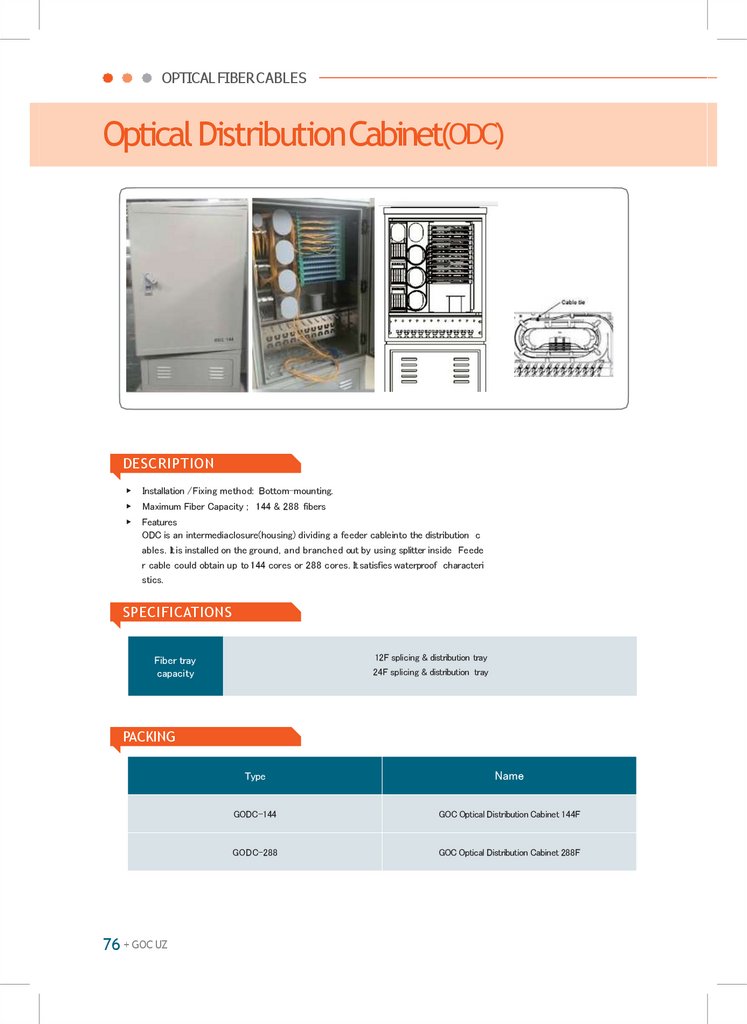
Optical
Distribution
Cabinet
(ODC)
Fi
76
Aerial
Type
Fiber
Optic
Terminal
Box
76
ber Type
OpticFiber
CableOptic
Clamp
77 Pole
Distribution Box
77
78 Optical
S-TypeDistribution
Fastener Cabinet (ODC)
78
79
Fiber
Optic
Cable
Clamp
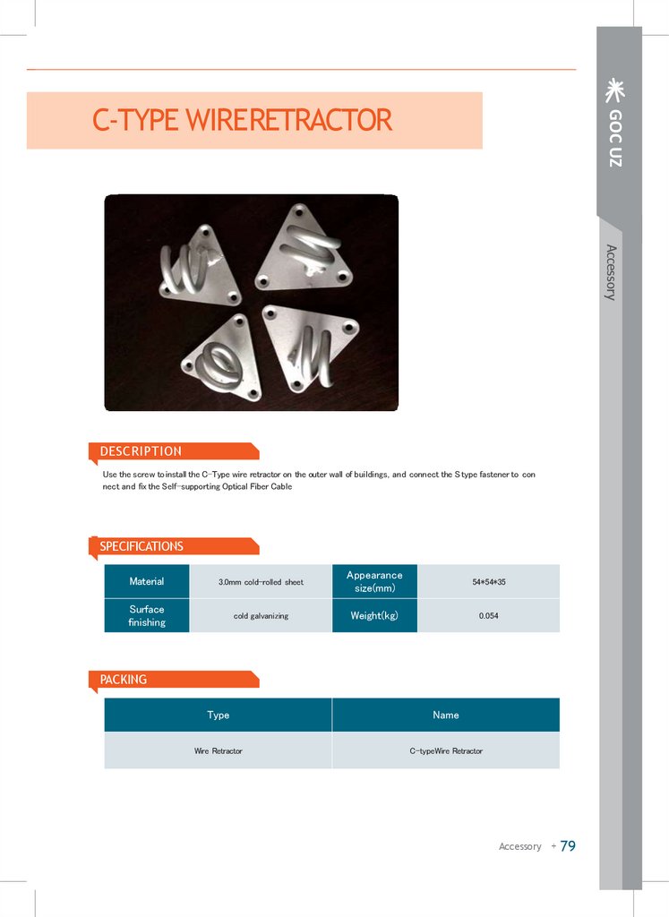
C-Type
Wire
Retractor
79
80 S-Type
OpticalFastener
ConnectorPlier
80
81 C-Type WireRetractor
82 Optical Connector Plier
3.
GOC UZFURCATIONTUBE
DESCRIPTION
▶
▶
▶
Tube
Inner Diameter
(500㎛)
Aramid y
Outer Diameter
(900㎛)
Outer Ja
(1.6~ 3.0
FEATURES
APPLICATIONS
▶
Accurate inner & outer diameters
▶
▶
Easy insertion of optical fiber or buffer
Connection to Single mode or Multimode optical
fiber
▶
Use of standard colors(Easy color identification)
▶
Connection between equipments
Operating Temperanture Range:0~60℃
▶
Separation of optical fiber & tight buffer joints
▶
Medical devices
▶
CHARACTERISTICS
Item
Simplex Fan Out Tube
Outer/Inner Diameter
of Tubing(mm)
Outer Diameter
of Fan Out Tubing(mm)
Weight(kg/km)
0.5/0.9
Duplex Fan Out Tubinf
1.2/1.6
0.9
2.0
2.4
2.8
2.0
0.8
3.6
5.3
6.6
8.0
Max. Tensile
Load(kg-f)
Installation
-
20
40
40
10
Operation
-
10
20
20
20
Min. Bending
Radius(mm)
Installation
18
40
48
60
60
Operation
9
20
24
30
30
Application
Color
Protection of 250 ㎛ optical fiber
Yellow
protection of 600&900
㎛ tight buffer fiber
Protection of 250 ㎛ optical fiber
Yellow or Orange Color
Indoor Cord & Cable + 5
Indoor Cord & Cable
▶
Furcation tube is used for protection of optical fiber or t
ight buffered fiber.
Coating considering the easy insertion of fiber core & f
lexibility for convenience of handling.
The Tube is manufactured using Aramid Yarn for Fan
Out Tubing, offering two types with Simplex Fan Out T
ubing & Duplex Fan Out Tubing, to enhance the Tensil
e Load and protect the optical fiber.
Consisting of two simplex Sub-units for Duplex Fan Out
Tubing enabling the insertion of 0.9mm tight buffers resp
ectively.
4.
OPTICAL FIBERCABLES600/900㎛DIAMETERTIGHTBUFFEREDFIBER
DESCRIPTION
▶
▶
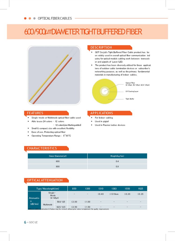
GOT Co.Ltd's Tight Buffered Fiber Cable product has be
en widely used in overall optical fiber communication ind
ustry for optical module cabling work between transceiv
er and pigtails of Laser/LED.
The product has been diversely utilized for those applicat
ions of outdoor cable termination devices or subscriber's
networking purpose, as well as the primary fundamental
materials in manufacturing of indoor cables.
Optical Fiber
(9/125㎛, 50/125㎛, 62.5/125㎛)
UV Coating Layer
Tight Buffer
FEATURES
APPLICATIONS
▶
Single-mode or Multimode optical fiber cable used
▶
For Indoor cabling
▶
Able to use 24 colors - 12 colors
▶
Used in pigtail
▶
Used in Passive/active devices
▶
- 12 colors(Line Markingadded)
Small & compact size with excellent flexibility
▶
Ease of use, Protecting optical fiber
▶
Operating Temperature Range : 0~60℃
CHARACTERISTICS
Outer Diameter(㎛)
Weight(kg/km)
600
0.4
900
0.9
OPTICAL ATTENUATION
Type/Wavelength(nm)
Atenuatio
n
(dB/km)
850
1300
1310
1383
1550
1625
-
-
≤0.40
≤1310nm
≤0.30
≤0.35
50.0/125
≤3.00
≤1.00
-
-
-
-
62.5/12.5
≤3.50
≤1.50
-
-
-
-
SingleMode
(9/125㎛)
Multimode
#Above cable construction & feature may be revised without prior notice to implement the quality improvement.
6 + GOC UZ
5.
GOC UZOPTICAL CORDCABLE
DESCRIPTION
▶
▶
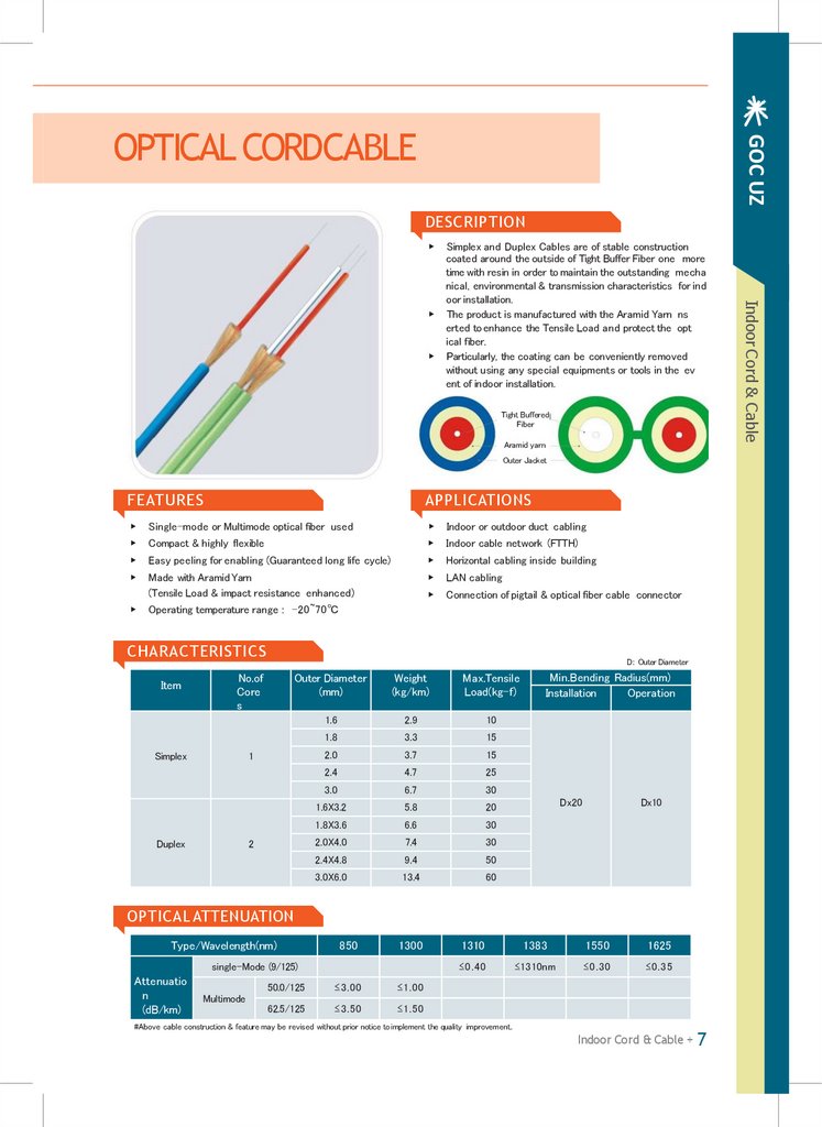
Tight Buffered
Fiber
Aramid yarn
Outer Jacket
FEATURES
APPLICATIONS
▶
▶
Single-mode or Multimode optical fiber used
Compact & highly flexible
▶
▶
Indoor or outdoor duct cabling
Indoor cable network (FTTH)
▶
Easy peeling for enabling (Guaranteed long life cycle)
▶
Horizontal cabling inside building
▶
Made with Aramid Yarn
(Tensile Load & impact resistance enhanced)
Operating temperature range : -20~70℃
▶
LAN cabling
▶
Connection of pigtail & optical fiber cable connector
▶
CHARACTERISTICS
Item
D: Outer Diameter
No.of
Core
s
Simplex
Outer Diameter
(mm)
Weight
(kg/km)
Max.Tensile
Load(kg-f)
1.6
2.9
10
1.8
3.3
15
2.0
3.7
15
2.4
4.7
25
1
Duplex
2
3.0
6.7
30
1.6X3.2
5.8
20
1.8X3.6
6.6
30
2.0X4.0
7.4
30
2.4X4.8
9.4
50
3.0X6.0
13.4
60
Min.Bending Radius(mm)
Installation
Operation
Dx20
Dx10
OPTICAL ATTENUATION
Type/Wavelength(nm)
850
1300
single-Mode (9/125)
Attenuatio
n
(dB/km)
Multimode
50.0/125
≤3.00
≤1.00
62.5/125
≤3.50
≤1.50
1310
1383
1550
1625
≤0.40
≤1310nm
≤0.30
≤0.35
#Above cable construction & feature may be revised without prior notice to implement the quality improvement.
Indoor Cord & Cable + 7
Indoor Cord & Cable
▶
Simplex and Duplex Cables are of stable construction
coated around the outside of Tight Buffer Fiber one more
time with resin in order to maintain the outstanding mecha
nical, environmental & transmission characteristics for ind
oor installation.
The product is manufactured with the Aramid Yarn ns
erted to enhance the Tensile Load and protect the opt
ical fiber.
Particularly, the coating can be conveniently removed
without using any special equipments or tools in the ev
ent of indoor installation.
6.
OPTICAL FIBERCABLES4C ZIPCORD
DESCRIPTION
▶
▶
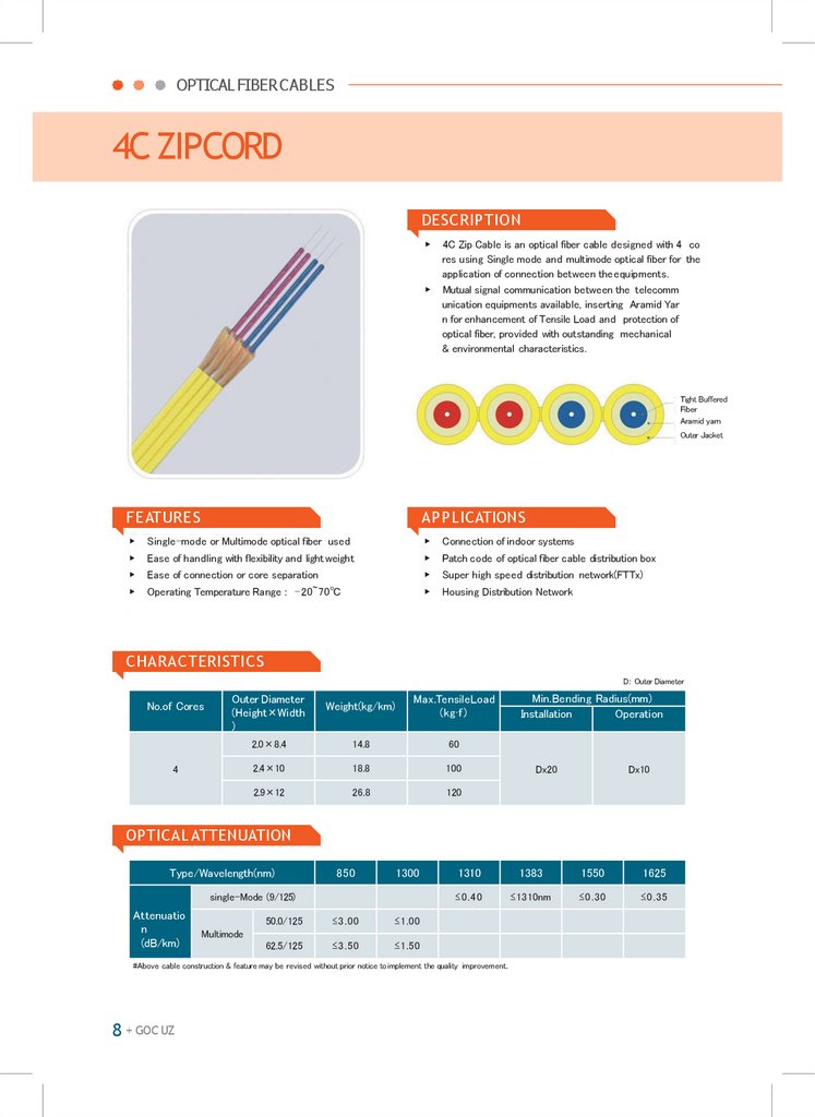
4C Zip Cable is an optical fiber cable designed with 4 co
res using Single mode and multimode optical fiber for the
application of connection between the equipments.
Mutual signal communication between the telecomm
unication equipments available, inserting Aramid Yar
n for enhancement of Tensile Load and protection of
optical fiber, provided with outstanding mechanical
& environmental characteristics.
Tight Buffered
Fiber
Aramid yarn
Outer Jacket
FEATURES
APPLICATIONS
▶
Single-mode or Multimode optical fiber used
▶
Connection of indoor systems
▶
Ease of handling with flexibility and light weight
▶
Patch code of optical fiber cable distribution box
▶
Ease of connection or core separation
▶
Super high speed distribution network(FTTx)
▶
Operating Temperature Range : -20~70℃
▶
Housing Distribution Network
CHARACTERISTICS
D: Outer Diameter
No.of Cores
Outer Diameter
(Height×Width
)
4
Weight(kg/km)
Max.TensileLoad
(kg·f)
2.0×8.4
14.8
60
2.4×10
18.8
100
2.9×12
26.8
120
Min.Bending Radius(mm)
Installation
Operation
Dx20
Dx10
OPTICAL ATTENUATION
Type/Wavelength(nm)
850
1300
single-Mode (9/125)
Attenuatio
n
(dB/km)
50.0/125
≤3.00
≤1.00
62.5/125
≤3.50
≤1.50
1310
1383
1550
1625
≤0.40
≤1310nm
≤0.30
≤0.35
Multimode
#Above cable construction & feature may be revised without prior notice to implement the quality improvement.
8 + GOC UZ
7.
GOC UZFLATCABLE
DESCRIPTION
▶
▶
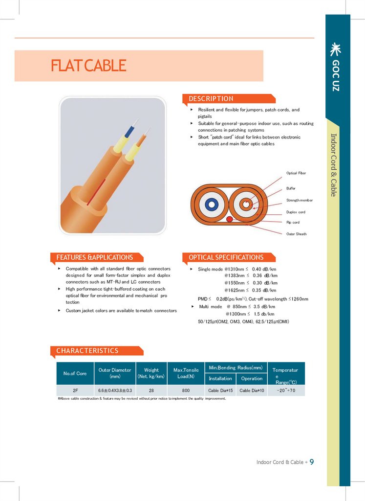
Optical Fiber
Buffer
Strength member
Duplex cord
Rip cord
Outer Sheath
FEATURES &APPLICATIONS
OPTICAL SPECIFICATIONS
▶
▶
▶
▶
Compatible with all standard fiber optic connectors
designed for small form-factor simplex and duplex
connecters such as MT-RJ and LC connecters
High performance tight-buffered coating on each
optical fiber for environmental and mechanical pro
tection
Single mode @1310nm ≤ 0.40 dB/km
@1383nm ≤ 0.36 dB/km
@1550nm ≤ 0.30 dB/km
@1625nm ≤ 0.35 dB/km
PMD ≤
▶
Custom jacket colors are available to match connectors
0.2dB(ps/km½), Cut-off wavelength ≤1260nm
Multi mode @ 850nm ≤ 3.5 dB/km
@1300nm ≤ 1.5 db/km
50/125㎛(OM2, OM3, OM4), 62.5/125㎛(OM1)
CHARACTERISTICS
No.of Core
Outer Diameter
(mm)
Weight
(Net. kg/km)
Max.Tensile
Load(N)
2F
6.6±0.4X3.8±0.3
28
800
Min.Bending Radius(mm)
Installation
Operation
Temperatur
e
Range(℃)
Cable Dia*15
Cable Dia*10
-20~+70
#Above cable construction & feature may be revised without prior notice to implement the quality improvement.
Indoor Cord & Cable + 9
Indoor Cord & Cable
▶
Resilient and flexible for jumpers, patch cords, and
pigtails
Suitable for general-purpose indoor use, such as routing
connections in patching systems
Short "patch cord" ideal for links between electronic
equipment and main fiber optic cables
8.
GOC UZDISTRIBUTION CABLE(DuctType)
DESCRIPTION
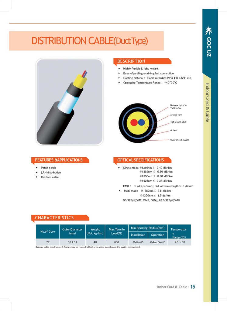
Highly flexible & light weight
▶
Ease of peeling enabling fast connection
▶
Coating material : Flame retardant PVC, PU, LSZH etc.
▶
Operating Temperature Range : -40~70℃
Nylon or hytrel Vo
Tight buffer
Aramid yarn
1ST. sheath LSZH
Al tape
Outer sheath LSZH
FEATURES &APPLICATIONS
OPTICAL SPECIFICATIONS
▶
Patch cords
▶
▶
LAN distribution
▶
Outdoor cable
Single mode @1310nm ≤ 0.40 dB/km
@1383nm ≤ 0.36 dB/km
@1550nm ≤ 0.30 dB/km
@1625nm ≤ 0.35 dB/km
PMD ≤
▶
0.2dB(ps/km½), Cut-off wavelength ≤ 1260nm
Multi mode @ 850nm ≤ 3.5 dB/km
@1300nm ≤ 1.5 db/km
50/125㎛(OM2, OM3, OM4), 62.5/125㎛(OM1)
CHARACTERISTICS
No.of Core
Outer Diameter
(mm)
Weight
(Net. kg/km)
Max.Tensile
Load(N)
2F
5.8±0.2
40
800
Min.Bending Radius(mm)
Installation
Operation
Temperatur
e
Range(℃)
Cable*15
Cable Dia*10
- 4 0 ~+ 6 0
#Above cable construction & feature may be revised without prior notice to implement the quality improvement.
Indoor Cord & Cable + 15
Indoor Cord & Cable
▶
9.
OPTICAL FIBERCABLESARMOREDDISTRIBUTIONCABLE(AerialType)
DESCRIPTION
▶
Used in areas that require a riser rating and are s
usceptible to damage from small non-burrowing r
odents
Optical fiber
buffer Aram
id yarn
Central strength member
Inner sheath
Rip cord
Tape
Corrugation steel tape
Outer sheath
FEATURES &APPLICATIONS
OPTICAL SPECIFICATIONS
▶
Include a layer of fiberglass yarn that provides an eff
ective deterrent to damage caused by small non- bur
rowing rodents(not recommended for direct burial ap
plications)
▶
▶
▶
FRP is ideal for use in surface installations
Cables are suitable for use with single, as well as multi
channel connectors
Single mode @1310nm ≤ 0.38 dB/km
@1383nm ≤ 0.38 dB/km
@1550nm ≤ 0.25 dB/km
@1625nm ≤ 0.28 dB/km
PMD ≤
▶
0.2dB(ps/km½), Cut-off wavelength ≤ 1260nm
Multi mode @ 850nm ≤ 3.0 dB/km
@1300nm ≤ 1.0 db/km
50/125㎛(OM2, OM3, OM4), 62.5/125㎛(OM1)
CHARACTERISTICS
No.of Core
Outer Diameter
(mm)
Weight
(Net. kg/km)
Max.Tensile
Load(N)
6F
5.8±0.2
125
800
12F
12.6±0.5
180
1,200
24F
20.1±0.5
415
1,800
Min.Bending Radius(mm)
Installation
Operation
Temperatur
e
Range(℃)
Cable*15
Cable Dia*10
-40~+70
#Above cable construction & feature may be revised without prior notice to implement the quality improvement.
16 + GOC UZ
10.
OPTICAL FIBERCABLESDUCTLOOSETUBECABLE(SJSA)
DESCRIPTION
▶
▶
Ideal for installations requiring a rugged and reliable
cable design where maximum mechanical and envir
onmental protection is necessary
Typical industrial uses are factory automation, power g
eneration and other utilities, oil and gas refining, and s
urface mining
Optical fiber
Jelly compound
Loose tube
Water swellable yarn Centr
al strength member
Water swellable tape
Corrugated steed tape
Outer jacket
FEATURES &APPLICATIONS
OPTICAL SPECIFICATIONS
▶
▶
▶
▶
▶
Best design for multimode and single-mode fiber
hybrid/composite cables
Design allows to be routed to multiple locations such
as wiring racks and closets
Designed for indoor/outdoor installations, including
cable trays
12-288 fiber configurations are available with 6-12
fibers per tube
Single mode @1310nm ≤ 0.36 dB/km
@1383nm ≤ 0.35 dB/km
@1550nm ≤ 0.22 dB/km
@1625nm ≤ 0.25 dB/km
PMD ≤
▶
0.2dB(ps/km½), Cut-off wavelength ≤ 1260nm
Multi mode @ 850nm ≤ 3.0 dB/km
@1300nm ≤ 1.0 db/km
50/125㎛(OM2, OM3, OM4), 62.5/125㎛(OM1)
CHARACTERISTICS
No.of Core
Outer Diameter
(mm)
Weight
(Net. kg/km)
4~24F
12.2±0.7
150
36~72F
12.5±0.7
160
96F
14.0±0.7
190
144F
16.3±0.7
250
288F
20.3±0.7
350
Max.Tensile
Load(N)
Min.Bending Radius(mm)
Installation
Operation
Temperatur
e
Range(℃)
Cable Dia*20
Cable Dia*15
-40~+70
1,500
2,000
2,500
#Above cable construction & feature may be revised without prior notice to implement the quality improvement.
18 + GOC UZ
11.
GOC UZDUCTLOOSETUBECABLE(Non-metallic)
DESCRIPTION
▶
▶
Optical fiber
Jelly
Loose tube
CSM
W/S yarn
W/S tape
Glass yarn
Rip cord Ou
ter jacker
FEATURES &APPLICATIONS
OPTICAL SPECIFICATIONS
▶
▶
▶
▶
▶
Best design for multimode and single-mode fiber
hybrid/composite cables
Design allows multi-fiber sub cables to be routed to
multiple location such as wiring racks and closets
Designed for indoor/outdoor installations, including
cable trays
12-288 fiber configurations are available with 6-12
fibers per tube
Single mode @1310nm ≤ 0.36 dB/km
@1383nm ≤ 0.35 dB/km
@1550nm ≤ 0.22 dB/km
@1625nm ≤ 0.25 dB/km
PMD ≤
▶
0.2dB(ps/km½), Cut-off wavelength ≤ 1260nm
Multi mode @ 850nm ≤ 3.5 dB/km
@1300nm ≤ 1.0 db/km
50/125㎛(OM2, OM3, OM4), 62.5/125㎛(OM1)
CHARACTERISTICS
No.of Core
Outer Diameter
(mm)
Weight
(Net. kg/km)
4~24F
11.8±0.7
95
36~72F
12.0±0.7
110
96F
13.7±0.7
140
144F
16.3±0.7
205
288F
20.0±0.7
300
Max.Tensile
Load(N)
Min.Bending Radius(mm)
Installation
Operation
Temperatur
e
Range(℃)
Cable Dia*20
Cable Dia*15
-20~+70
1,500
2,000
2,500
#Above cable construction & feature may be revised without prior notice to implement the quality improvement.
LooseTube Cable
+ 19
LooseTube Cable
Ideal for installations requiring a rugged and reliable
cable design where maximum mechanical and envir
onmental protection is necessary
Typical industrial uses are factory automation, power g
eneration and other utilities, oil and gas refining, and s
urface mining
12.
OPTICAL FIBERCABLESFLAMERETARDANTDUCTLOOSETUBECABLE
DESCRIPTION
▶
▶
Indoor/outdoor tight-biffered design allows cables to be i
nstalled in intra-building backbone and inter-building ca
mpus location without costly transitions between cable ty
pes
Design allow multi fiber sub cables to be routed to
multiple locations such as wiring racks and closets
Optical fiber Jell
y compound
PBT loose tube Wate
r swellable yarn
Central strength member
Filler
Water swellable tape
Outer sheath
FEATURES &APPLICATIONS
OPTICAL SPECIFICATIONS
▶
▶
▶
▶
High performance components and construction
UL Listed in accordance with NEC sections 770.179(b)
for use in vertical runs in building riser shafts or from to
floor
Cable materials are indoor/outdoor : UV, water and
fungus resistant
Wide operating temperature range : -40~85℃
Single mode @1310nm ≤ 0.36 dB/km
@1383nm ≤ 0.35 dB/km
@1550nm ≤ 0.22 dB/km
@1625nm ≤ 0.25 dB/km
PMD ≤
▶
0.2dB(ps/km½), Cut-off wavelength ≤ 1260nm
Multi mode @ 850nm ≤ 3.0 dB/km
@1300nm ≤ 1.0 db/km
50/125㎛(OM2, OM3, OM4), 62.5/125㎛(OM1)
CHARACTERISTICS
No.of Core
Outer Diameter
(mm)
Weight
(Net. kg/km)
Max.Tensile
Load(N)
10.7±0.5
120
1,500
Min.Bending Radius(mm)
Installation
Operation
Temperatur
e
Range(℃)
Cable Dia*20
Cable Dia*15
-40~+70
4F
8F
12F
16F
24F
#Above cable construction & feature may be revised without prior notice to implement the quality improvement.
20 + GOC UZ
13.
GOC UZADSS CABLE (SingleJacket)
DESCRIPTION
▶
▶
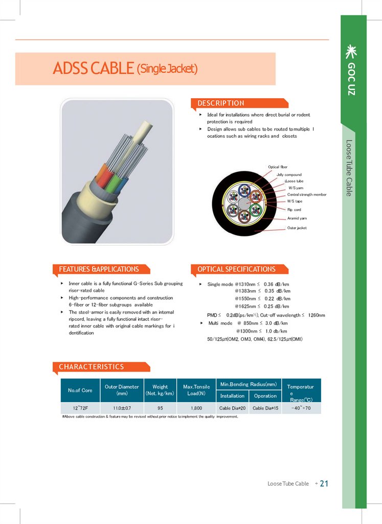
Ideal for installations where direct burial or rodent
protection is required
Design allows sub cables to be routed to multiple l
ocations such as wiring racks and closets
Jelly compound
Loose tube
W/S yarn
Central strength member
W/S tape
Rip cord
Aramid yarn
Outer jacket
FEATURES &APPLICATIONS
OPTICAL SPECIFICATIONS
▶
▶
▶
▶
Inner cable is a fully functional G-Series Sub grouping
riser-rated cable
High-performance components and construction
6-fiber or 12-fiber subgroups available
The steel-armor is easily removed with an internal
ripcord, leaving a fully functional intact riserrated inner cable with original cable markings for i
dentification
Single mode @1310nm ≤ 0.36 dB/km
@1383nm ≤ 0.35 dB/km
@1550nm ≤ 0.22 dB/km
@1625nm ≤ 0.25 dB/km
PMD ≤
▶
0.2dB(ps/km½), Cut-off wavelength ≤ 1260nm
Multi mode @ 850nm ≤ 3.0 dB/km
@1300nm ≤ 1.0 db/km
50/125㎛(OM2, OM3, OM4), 62.5/125㎛(OM1)
CHARACTERISTICS
No.of Core
Outer Diameter
(mm)
Weight
(Net. kg/km)
Max.Tensile
Load(N)
12~72F
11.0±0.7
95
1,800
Min.Bending Radius(mm)
Installation
Operation
Temperatur
e
Range(℃)
Cable Dia*20
Cable Dia*15
-40~+70
#Above cable construction & feature may be revised without prior notice to implement the quality improvement.
LooseTube Cable
+ 21
LooseTube Cable
Optical fiber
14.
OPTICAL FIBERCABLESADSS CABLE (DoubleJacket)
DESCRIPTION
▶
▶
Ideal for installations where direct burial or rodent
protection is required
Design allows sub cables to be routed to multiple l
ocations such as witing racks and closets
Optical fiber
Jelly compound
Loose tube
W/S yarn
Central strength member
W/S tape
Rip cord
Inner jacket
Aramid yarn
Outer jacket
FEATURES &APPLICATIONS
OPTICAL SPECIFICATIONS
▶
▶
▶
▶
Inner cable is a fully functional G-Series Sub grouping
riser-rated cable
High-performance components and construction
6-fiber or 12-fiber subgroups available
The steel-armor is easily removed with an internal
ripcord, leaving a fully functional intact riserrated inner cable with original cable markings for i
dentification
Single mode @1310nm ≤ 0.36 dB/km
@1383nm ≤ 0.35 dB/km
@1550nm ≤ 0.22 dB/km
@1625nm ≤ 0.25 dB/km
PMD ≤
▶
0.2dB(ps/km½), Cut-off wavelength ≤ 1260nm
Multi mode @ 850nm ≤ 3.0 dB/km
@1300nm ≤ 1.0 db/km
50/125㎛(OM2, OM3, OM4), 62.5/125㎛(OM1)
CHARACTERISTICS
No.of Core
Outer Diameter
(mm)
Weight
(Net. kg/km)
Max.Tensile
Load(N)
12~72F
14.2±1.0
150
4,000
Min.Bending Radius(mm)
Installation
Operation
Temperatur
e
Range(℃)
Cable Dia*20
Cable Dia*15
-30~+70
#Above cable construction & feature may be revised without prior notice to implement the quality improvement.
22 + GOC UZ
15.
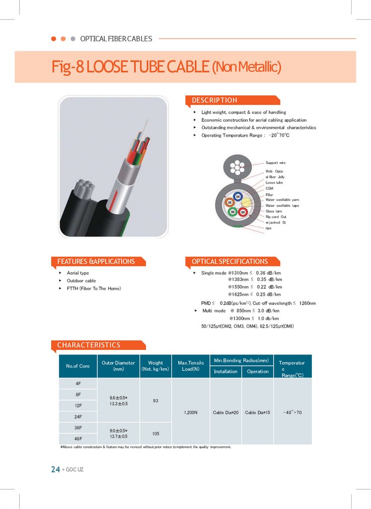
OPTICAL FIBERCABLESFig-8LOOSETUBECABLE (NonMetallic)
DESCRIPTION
▶
Light weight, compact & ease of handling
▶
Economic construction for aerial cabling application
▶
Outstanding mechanical & environmental characteristics
▶
Operating Temperature Range : -20~70℃
Support wire
Web Optic
al fiber Jelly
Loose tube
CSM
Filler
Water swellable yarn
Water swellable tape
Glass tarn
Rip cord Out
er jacked St
ripe
FEATURES &APPLICATIONS
OPTICAL SPECIFICATIONS
▶
Aerial type
▶
▶
Outdoor cable
▶
FTTH (Fiber To The Home)
Single mode @1310nm ≤ 0.36 dB/km
@1383nm ≤ 0.35 dB/km
@1550nm ≤ 0.22 dB/km
@1625nm ≤ 0.25 dB/km
PMD ≤
▶
0.2dB(ps/km½), Cut-off wavelength ≤ 1260nm
Multi mode @ 850nm ≤ 3.0 dB/km
@1300nm ≤ 1.0 db/km
50/125㎛(OM2, OM3, OM4), 62.5/125㎛(OM1)
CHARACTERISTICS
No.of Core
Outer Diameter
(mm)
Weight
(Net. kg/km)
8.6±0.5*
13.3±0.5
93
Max.Tensile
Load(N)
Min.Bending Radius(mm)
Installation
Operation
Temperatur
e
Range(℃)
Cable Dia*20
Cable Dia*15
-40~+70
4F
8F
12F
1,200N
24F
36F
48F
9.0±0.5*
13.7±0.5
105
#Above cable construction & feature may be revised without prior notice to implement the quality improvement.
24 + GOC UZ
16.
GOC UZAERIAL LOOSETUBECABLE
DESCRIPTION
▶
▶
Wide operating temperature range of -40℃ to+85℃
Messenger unit
Web
Optical fiber Jell
y compound L
oose tube
water swellable yam
CSM
Water blocking tape
Rip cord
Al tape
Outer jacket
FEATURES &APPLICATIONS
OPTICAL SPECIFICATIONS
▶
Outdoor aerial installations along utility poles for cabl
e television, telecom or other outside plant campus
backbone applications without the need fof cable la
shing
▶
▶
▶
1/4-inch galvanized messenger standard
Polyethylene outer cable jacket for excellent UV and
weather resistance
Single mode @1310nm ≤ 0.36 dB/km
@1383nm ≤ 0.35 dB/km
@1550nm ≤ 0.22 dB/km
@1625nm ≤ 0.25 dB/km
PMD ≤
▶
0.2dB(ps/km½), Cut-off wavelength ≤ 1260nm
Multi mode @ 850nm ≤ 3.0 dB/km
@1300nm ≤ 1.0 db/km
50/125㎛(OM2, OM3, OM4), 62.5/125㎛(OM1)
CHARACTERISTICS
No.of Core
Outer Diameter
(mm)
Weight
(Net. kg/km)
4~72F
10.5±0.7*17.6±0.7
160
96F
12.7±0.7*19.8±0.7
205
144F
15.3±0.7*22.4±0.7
270
Max.Tensile
Load(N)
5,000
Min.Bending Radius(mm)
Installation
Operation
Temperatur
e
Range(℃)
Cable Dia*20
Cable Dia*15
-40~+70
#Above cable construction & feature may be revised without prior notice to implement the quality improvement.
LooseTube Cable
+ 25
LooseTube Cable
▶
Figure-eight construction for use with standard messeng
clamping and support hardware.
Deal for new installations. The figure-eight messenger c
able reduces installation time and cost by approximatel 5
0% compared to separate installation of a messenger wir
e and the lashing of the cable to the messenger.
17.
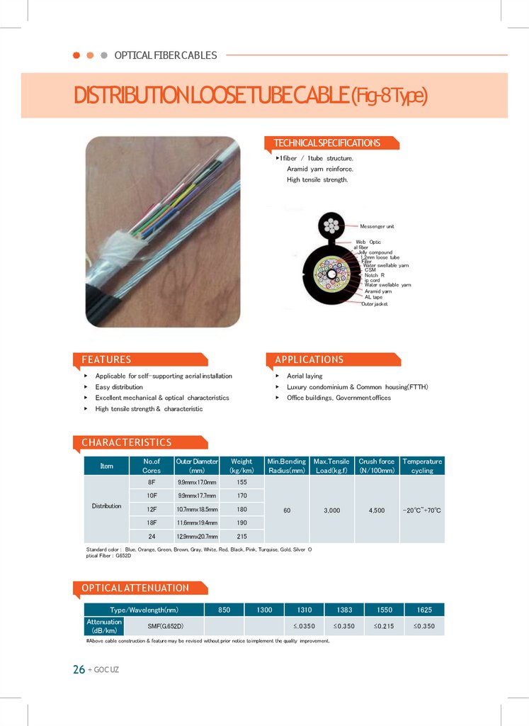
OPTICAL FIBERCABLESDISTRIBUTIONLOOSETUBECABLE(Fig-8Type)
TECHNICALSPECIFICATIONS
▶1fiber / 1tube structure.
Aramid yarn reinforce.
High tensile strength.
Messenger unit
Web Optic
al fiber
Jelly compound
1.2mm loose tube
Filler
Water swellable yarn
CSM
Notch R
ip cord
Water swellable yarn
Aramid yarn
AL tape
Outer jacket
FEATURES
APPLICATIONS
▶
Applicable for self-supporting aerial installation
▶
Aerial laying
▶
Easy distribution
▶
Luxury condominium & Common housing(FTTH)
▶
Excellent mechanical & optical characteristics
▶
Office buildings, Government offices
▶
High tensile strength & characteristic
CHARACTERISTICS
Item
Distribution
No.of
Cores
Outer Diameter
(mm)
Weight
(kg/km)
8F
9.9mmx17.0mm
155
10F
9.9mmx17.7mm
170
12F
10.7mmx18.5mm
180
18F
11.6mmx19.4mm
190
24
12.9mmx20.7mm
215
Min.Bending
Radius(mm)
Max.Tensile
Load(kg.f)
Crush force
(N/100mm)
Temperature
cycling
60
3,000
4,500
-20℃~+70℃
Standard color : Blue, Orange, Green, Brown, Gray, White, Red, Black, Pink, Turquise, Gold, Silver O
ptical Fiber : G652D
OPTICAL ATTENUATION
Type/Wavelength(nm)
Attenuation
(dB/km)
SMF(G.652D)
850
1300
1310
1383
1550
1625
≤.0350
≤0.350
≤0.215
≤0.350
#Above cable construction & feature may be revised without prior notice to implement the quality improvement.
26 + GOC UZ
18.
GOC UZDISTRIBUTIONLOOSETUBECABLE(DuctType)
CROSS SECTION
▶
1fiber / 1tube structure.
Aramid yarn reinforce.
High tensile strength.
Filler
Water swellable yarn
CSM
Rip cord
Water swellable yarn
Aramid yarn
AL tape
Outer jacket
FEATURES
APPLICATIONS
▶
Applicable for duct or aerial installation
▶
Aerial laying
▶
Easy distribution
▶
Luxury condominium & common housing(FTTH)
▶
Excellent mechanical & optical characteristics
▶
Office buildings, Government offices
▶
High tensile strength & characteristic
CHARACTERISTICS
Item
Distribution
No.of
Cores
Outer Diameter
(mm)
Weight
(kg/km)
8F
10.0mm
85
10F
10.7mm
100
12F
11.5mm
115
18F
12.4mm
120
24
13.7mm
150
Min.Bending
Radius(mm)
Max.Tensile
Load(kg.f)
60
3,000
Crush force Temperature
(N/100mm)
cycling
4,500
-20~+70
Standard color : Blue, Orange, Green, Brown, Gray, White, Red, Black, Pink, Turquise, Gold, Silver O
ptical Fiber : G652D
OPTICAL SPECIFICATIONS
Type/Wavelength(nm)
Attenuation
(dB/km)
SMF(G.652D)
850
1300
1310
1383
1550
1625
≤.0350
≤0.350
≤0.215
≤0.350
#Above cable construction & feature may be revised without prior notice to implement the quality improvement.
LooseTube Cable
+ 27
LooseTube Cable
Optical fiber
Jelly compound
1.2mm loose tube
19.
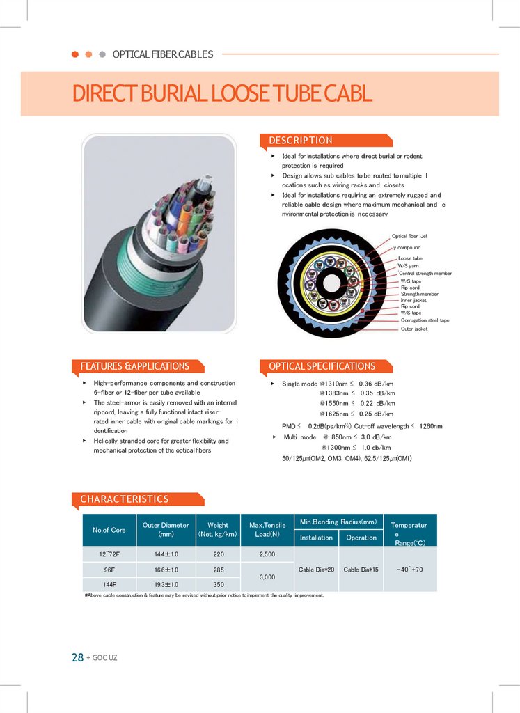
OPTICAL FIBERCABLESDIRECTBURIALLOOSETUBECABL
DESCRIPTION
▶
▶
▶
Ideal for installations where direct burial or rodent
protection is required
Design allows sub cables to be routed to multiple l
ocations such as wiring racks and closets
Ideal for installations requiring an extremely rugged and
reliable cable design where maximum mechanical and e
nvironmental protection is necessary
Optical fiber Jell
y compound
Loose tube
W/S yarn
Central strength member
W/S tape
Rip cord
Strength member
Inner jacket
Rip cord
W/S tape
Corrugation steel tape
Outer jacket
FEATURES &APPLICATIONS
OPTICAL SPECIFICATIONS
▶
▶
▶
▶
High-performance components and construction
6-fiber or 12-fiber per tube available
The steel-armor is easily removed with an internal
ripcord, leaving a fully functional intact riserrated inner cable with original cable markings for i
dentification
Helically stranded core for greater flexibility and
mechanical protection of the opticalfibers
Single mode @1310nm ≤ 0.36 dB/km
@1383nm ≤ 0.35 dB/km
@1550nm ≤ 0.22 dB/km
@1625nm ≤ 0.25 dB/km
PMD ≤
▶
0.2dB(ps/km½), Cut-off wavelength ≤ 1260nm
Multi mode @ 850nm ≤ 3.0 dB/km
@1300nm ≤ 1.0 db/km
50/125㎛(OM2, OM3, OM4), 62.5/125㎛(OM1)
CHARACTERISTICS
No.of Core
Outer Diameter
(mm)
Weight
(Net. kg/km)
Max.Tensile
Load(N)
12~72F
14.4±1.0
220
2,500
96F
16.6±1.0
285
Min.Bending Radius(mm)
Installation
Operation
Temperatur
e
Range(℃)
Cable Dia*20
Cable Dia*15
-40~+70
3,000
144F
19.3±1.0
350
#Above cable construction & feature may be revised without prior notice to implement the quality improvement.
28 + GOC UZ
20.
GOC UZCENTRALLOOSETUBECABLE
DESCRIPTION
▶
Suitable outdoor application (Aerial Installation)
▶
ABC(Air BlownCable)
LooseTube Cable
Optical fiber
Jelly compound
Polycarbonate tube
Water swellable yarn
Aramid yarn
Outer jacket
FEATURES &APPLICATIONS
OPTICAL SPECIFICATIONS
▶
Easy handling, small, light
▶
▶
Duct type, Aerial type
Single mode @1310nm ≤ 0.38 dB/km
@1383nm ≤ 0.38 dB/km
@1550nm ≤ 0.25 dB/km
@1625nm ≤ 0.28 dB/km
PMD ≤
▶
0.2dB(ps/km½), Cut-off wavelength ≤ 1260nm
Multi mode @ 850nm ≤ 3.0 dB/km
@1300nm ≤ 1.0 db/km
50/125㎛(OM2, OM3, OM4), 62.5/125㎛(OM1)
CHARACTERISTICS
No.of Core
Outer Diameter
(mm)
Weight
(Net. kg/km)
Max.Tensile
Load(N)
Duct 2~12
4.5±0.2
16.0
Aerial 2~12
5.0±9.4
55.0
Min.Bending Radius(mm)
Installation
Operation
Temperatur
e
Range(℃)
800
Cable Dia*15
Cable Dia*10
-30~+70
1,500
Cable Dia*15
Cable Dia*10
-30~+70
#Above cable construction & feature may be revised without prior notice to implement the quality improvement.
LooseTube Cable
+ 29
21.
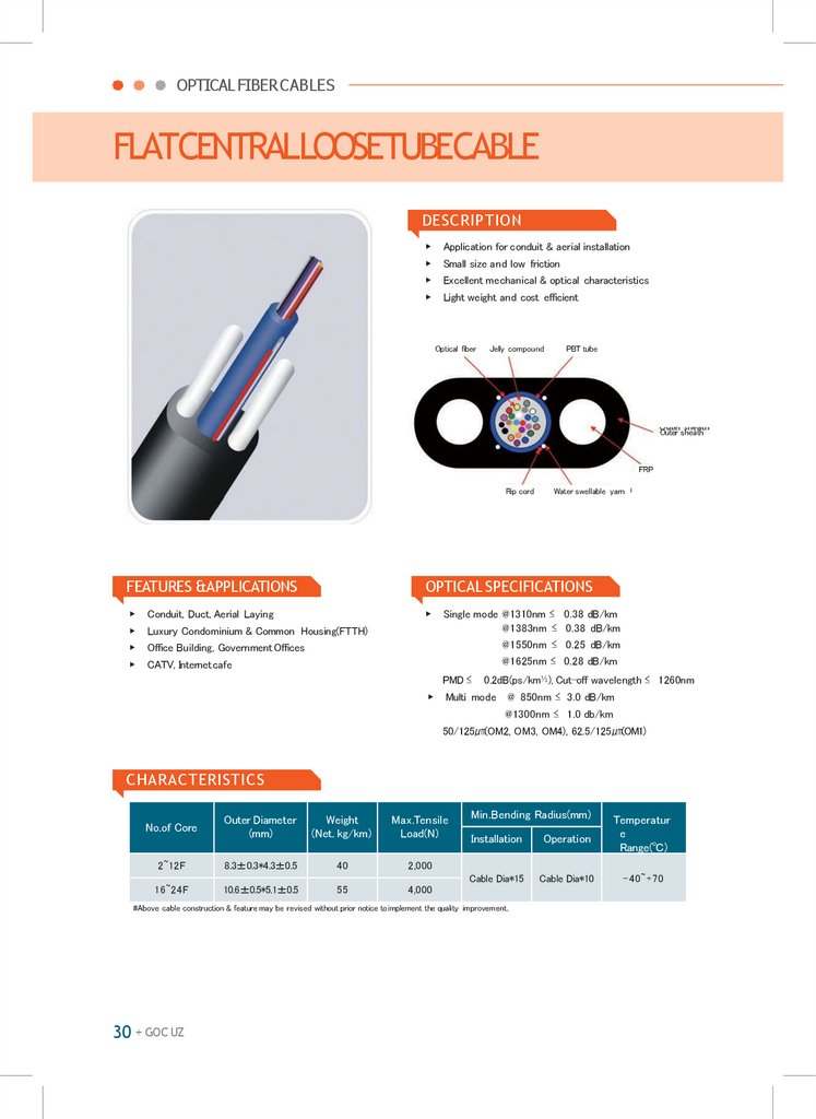
OPTICAL FIBERCABLESFLATCENTRALLOOSETUBECABLE
DESCRIPTION
▶
Application for conduit & aerial installation
▶
Small size and low friction
▶
Excellent mechanical & optical characteristics
▶
Light weight and cost efficient
Optical fiber
Jelly compound
PBT tube
Outer sheath
FRP
Rip cord
Water swellable yarn
FEATURES &APPLICATIONS
OPTICAL SPECIFICATIONS
▶
Conduit, Duct, Aerial Laying
▶
▶
Luxury Condominium & Common Housing(FTTH)
▶
Office Building, Government Offices
▶
CATV, Internetcafe
Single mode @1310nm ≤ 0.38 dB/km
@1383nm ≤ 0.38 dB/km
@1550nm ≤ 0.25 dB/km
@1625nm ≤ 0.28 dB/km
PMD ≤
▶
0.2dB(ps/km½), Cut-off wavelength ≤ 1260nm
Multi mode @ 850nm ≤ 3.0 dB/km
@1300nm ≤ 1.0 db/km
50/125㎛(OM2, OM3, OM4), 62.5/125㎛(OM1)
CHARACTERISTICS
No.of Core
Outer Diameter
(mm)
Weight
(Net. kg/km)
Max.Tensile
Load(N)
2~12F
8.3±0.3*4.3±0.5
40
2,000
16~24F
10.6±0.5*5.1±0.5
55
4,000
Min.Bending Radius(mm)
Installation
Operation
Temperatur
e
Range(℃)
Cable Dia*15
Cable Dia*10
-40~+70
#Above cable construction & feature may be revised without prior notice to implement the quality improvement.
30 + GOC UZ
22.
GOC UZARMOREDCENTRALLOOSETUBECABLE
DESCRIPTION
Highly flexible & light weight
▶
Ease of peeling enabling fast connection
▶
Coating material : flame retardant PVC, PU, LSZH etc.
▶
Operating Temperature Range : -40~70℃
LooseTube Cable
▶
Optical fiber
Jelly compound
Polycarbonate tube
Water swellable yarn
Aramid yarn
Rip cord
Inner jacket
Water swellable tape
Corrugated steel tape
Outer jacket
FEATURES &APPLICATIONS
OPTICAL SPECIFICATIONS
▶
LAN distribution
▶
▶
Outdoor cable
Single mode @1310nm ≤ 0.38 dB/km
@1383nm ≤ 0.38 dB/km
@1550nm ≤ 0.25 dB/km
@1625nm ≤ 0.28 dB/km
PMD ≤
▶
0.2dB(ps/km½), Cut-off wavelength ≤ 1260nm
Multi mode @ 850nm ≤ 3.0 dB/km
@1300nm ≤ 1.0 db/km
50/125㎛(OM2, OM3, OM4), 62.5/125㎛(OM1)
CHARACTERISTICS
No.of Core
Outer Diameter
(mm)
Weight
(Net. kg/km)
Max.Tensile
Load(N)
8.8±0.3
76
1,500
Min.Bending Radius(mm)
Installation
Operation
Temperatur
e
Range(℃)
Cable Dia*15
Cable Dia*10
-40~+70
2F
4F
6F
8F
12F
#Above cable construction & feature may be revised without prior notice to implement the quality improvement.
LooseTube Cable
+ 31
23.
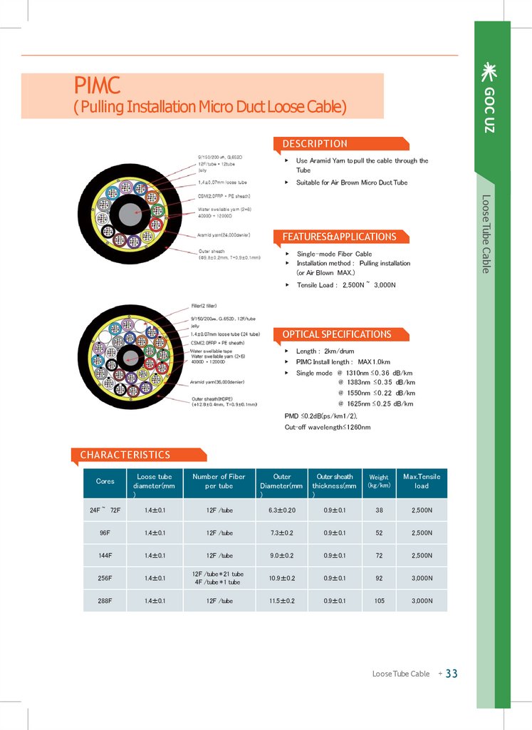
GOC UZPIMC
(Pulling Installation Micro Duct Loose Cable)
DESCRIPTION
▶
Use Aramid Yarn to pull the cable through the
Tube
▶
Suitable for Air Brown Micro Duct Tube
LooseTube Cable
FEATURES&APPLICATIONS
▶
▶
Single-mode Fiber Cable
Installation method : Pulling installation
(or Air Blown MAX.)
▶
Tensile Load : 2,500N ~ 3,000N
OPTICAL SPECIFICATIONS
▶
Length : 2km/drum
▶
PIMC Install length : MAX1.0km
▶
Single mode @ 1310nm ≤0.36 dB/km
@ 1383nm ≤0.35 dB/km
@ 1550nm ≤0.22 dB/km
@ 1625nm ≤0.25 dB/km
PMD ≤0.2dB(ps/km1/2),
Cut-off wavelength≤1260nm
CHARACTERISTICS
Loose tube
diameter(mm
)
Number of Fiber
per tube
Outer
Diameter(mm
)
Outer sheath
thickness(mm
)
Weight
(kg/km)
Max.Tensile
load
24F ~ 72F
1.4±0.1
12F /tube
6.3±0.20
0.9±0.1
38
2,500N
96F
1.4±0.1
12F /tube
7.3±0.2
0.9±0.1
52
2,500N
144F
1.4±0.1
12F /tube
9.0±0.2
0.9±0.1
72
2,500N
256F
1.4±0.1
12F /tube * 21 tube
4F /tube * 1 tube
10.9±0.2
0.9±0.1
92
3,000N
288F
1.4±0.1
12F /tube
11.5±0.2
0.9±0.1
105
3,000N
Cores
LooseTube Cable
+ 33
24.
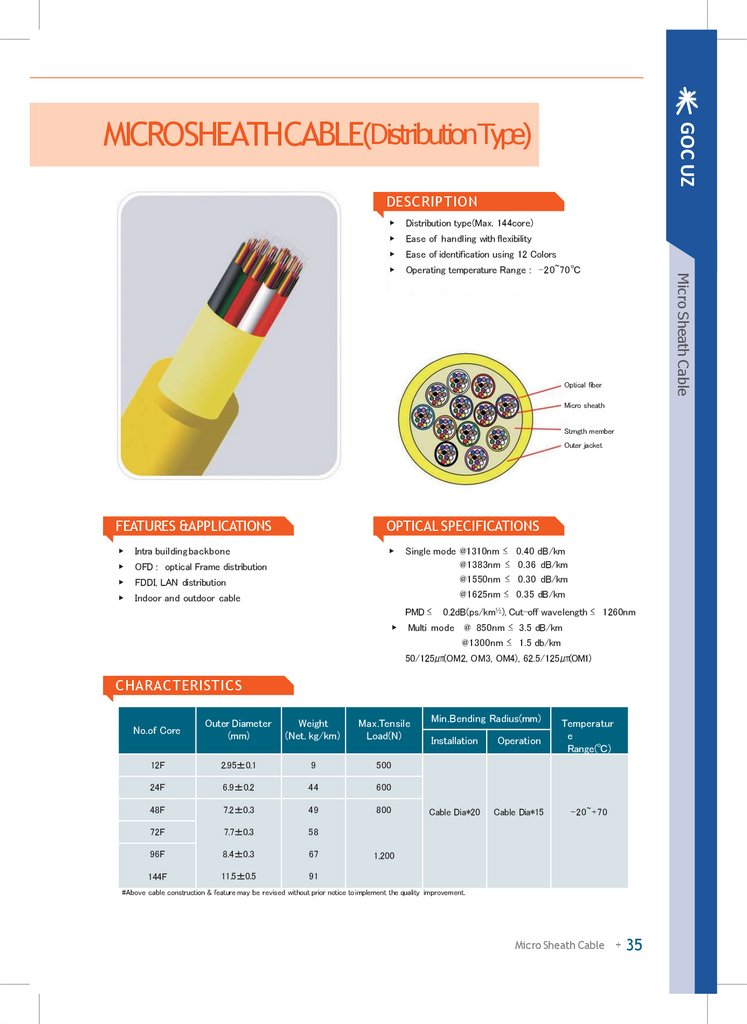
GOC UZMICROSHEATHCABLE(DistributionType)
DESCRIPTION
Distribution type(Max. 144core)
▶
Ease of handling with flexibility
▶
Ease of identification using 12 Colors
▶
Operating temperature Range : -20~70℃
Micro Sheath Cable
▶
Optical fiber
Micro sheath
Strngth member
Outer jacket
FEATURES &APPLICATIONS
OPTICAL SPECIFICATIONS
▶
Intra building backbone
▶
▶
OFD : optical Frame distribution
▶
FDDI, LAN distribution
▶
Indoor and outdoor cable
Single mode @1310nm ≤ 0.40 dB/km
@1383nm ≤ 0.36 dB/km
@1550nm ≤ 0.30 dB/km
@1625nm ≤ 0.35 dB/km
PMD ≤
▶
0.2dB(ps/km½), Cut-off wavelength ≤ 1260nm
Multi mode @ 850nm ≤ 3.5 dB/km
@1300nm ≤ 1.5 db/km
50/125㎛(OM2, OM3, OM4), 62.5/125㎛(OM1)
CHARACTERISTICS
No.of Core
Outer Diameter
(mm)
Weight
(Net. kg/km)
Max.Tensile
Load(N)
12F
2.95±0.1
9
500
24F
6.9±0.2
44
600
48F
7.2±0.3
49
800
72F
7.7±0.3
58
96F
8.4±0.3
67
144F
11.5±0.5
91
Min.Bending Radius(mm)
Installation
Operation
Temperatur
e
Range(℃)
Cable Dia*20
Cable Dia*15
-20~+70
1,200
#Above cable construction & feature may be revised without prior notice to implement the quality improvement.
Micro Sheath Cable
+ 35
25.
GOC UZFIG-8MICROSHEATHCABLE
DESCRIPTION
Light weight, compact & ease of handling
▶
Economic construction for aerial cabling application
▶
Outstanding mechanical & environmental characteristics
▶
Operating Temperature Range : -40~70℃
Micro Sheath Cable
▶
Messenger unit
Steel wire
Coloring fiber
Aramid yarn
Inner jacket
Outer jacket
FEATURES &APPLICATIONS
OPTICAL SPECIFICATIONS
▶
Aerial type
▶
▶
Outdoor cable
▶
FTTH (Fiber To The Home)
Single mode @1310nm ≤ 0.40 dB/km
@1383nm ≤ 0.36 dB/km
@1550nm ≤ 0.30 dB/km
@1625nm ≤ 0.35 dB/km
PMD ≤
▶
0.2dB(ps/km½), Cut-off wavelength ≤ 1260nm
Multi mode @ 850nm ≤ 3.5 dB/km
@1300nm ≤ 1.5 db/km
50/125㎛(OM2, OM3, OM4), 62.5/125㎛(OM1)
CHARACTERISTICS
No.of Core
Min.Bending Radius(mm)
Outer Diameter
(mm)
Weight
(Net. kg/km)
Max.Tensile
Load(N)
Installation
Operation
Temperatur
e
Range(℃)
5.0±0.3*8.0±0.3
45
1,000
Cable Dia*15
Cable Dia*10
-40~+70
4F
6F
12F
#Above cable construction & feature may be revised without prior notice to implement the quality improvement.
Micro Sheath Cable
+ 37
26.
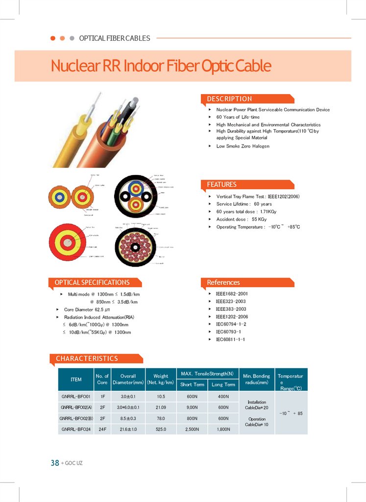
OPTICAL FIBERCABLESNuclearRR IndoorFiberOpticCable
DESCRIPTION
▶
Nuclear Power Plant Serviceable Communication Device
▶
60 Years of Life-time
▶
▶
High Mechanical and Environmental Characteristics
High Durability against High Temperature(110 ℃) by
applying Special Material
▶
Low Smoke Zero Halogen
FEATURES
OPTICAL SPECIFICATIONS
▶
▶
▶
▶
Vertical Tray Flame Test : IEEE1202(2006)
▶
Service Lifetime : 60 years
▶
60 years total dose : 1.71KGy
▶
Accident dose : 55 KGy
▶
Operating Temperature : -10℃ ~ +85℃
References
Multi mode @ 1300nm ≤ 1.5dB/km
▶ IEEE1682-2001
@ 850nm ≤ 3.5dB/km
▶ IEEE323-2003
Core Diameter 62.5 ㎛
▶ IEEE383-2003
Radiation Induced Attenuation(RIA)
▶ IEEE1202-2006
≤ 6dB/km(~100Gy) @ 1300nm
▶
IEC60794-1-2
≤ 10dB/km(~55KGy) @ 1300nm
▶
IEC60793-1
▶
IEC60811-1-1
CHARACTERISTICS
ITEM
No. of
Overall
Weight
Core Diameter(mm) (Net. kg/km)
MAX. TensileStrength(N)
Short Term
Long Term
GNRRL-BFO01
1F
3.0±0.1
10.5
600N
400N
GNRRL-BFO02(A)
2F
3.0*6.0±0.1
21.09
9,00N
600N
GNRRL-BFO02(B)
2F
8.5±0.3
78.0
800N
600N
GNRRL-BFO24
24F
21.6±1.0
525.0
2,500N
1,800N
Min. Bending
radius(mm)
Temperatur
e
Range(℃)
Installation
CableDia* 20
-10 ~ + 85
38 + GOC UZ
Operation
CableDia* 10
27.
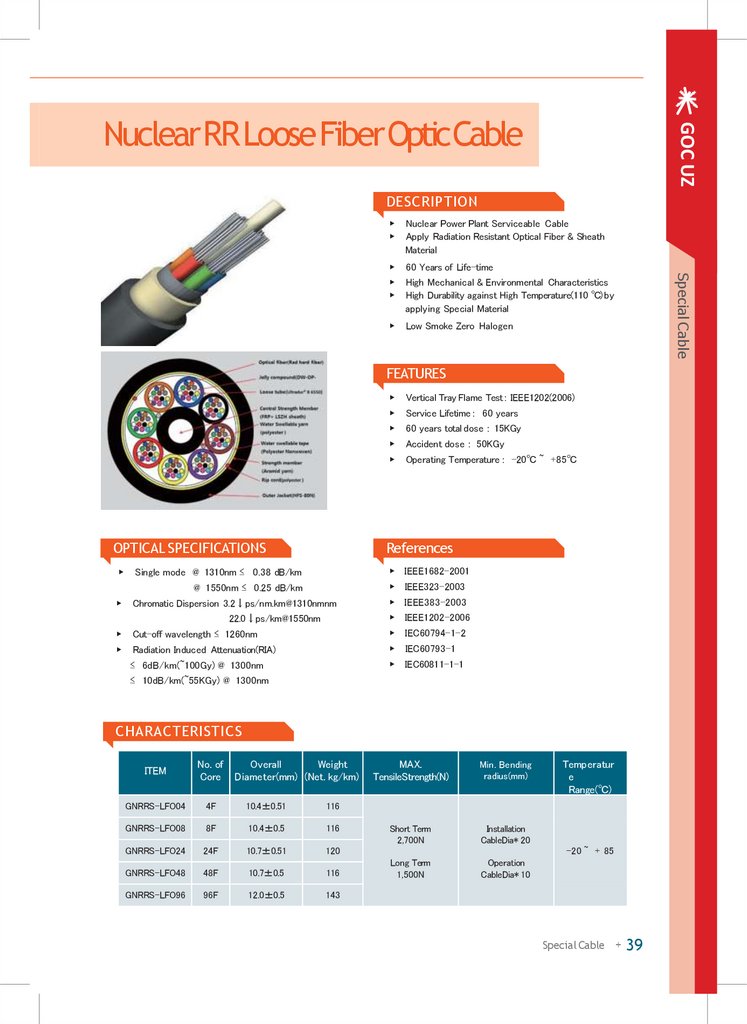
GOC UZNuclearRRLooseFiberOpticCable
DESCRIPTION
Nuclear Power Plant Serviceable Cable
Apply Radiation Resistant Optical Fiber & Sheath
Material
▶
60 Years of Life-time
▶
▶
High Mechanical & Environmental Characteristics
High Durability against High Temperature(110 ℃) by
applying Special Material
▶
Low Smoke Zero Halogen
FEATURES
▶
Vertical Tray Flame Test : IEEE1202(2006)
▶
Service Lifetime : 60 years
▶
60 years total dose : 15KGy
▶
Accident dose : 50KGy
▶
Operating Temperature : -20℃ ~ +85℃
OPTICAL SPECIFICATIONS
References
▶
Single mode @ 1310nm ≤ 0.38 dB/km
▶ IEEE1682-2001
@ 1550nm ≤ 0.25 dB/km
▶ IEEE323-2003
▶
Chromatic Dispersion 3.2↓ps/nm.km@1310nmnm
▶ IEEE383-2003
▶ IEEE1202-2006
22.0↓ps/km@1550nm
▶
Cut-off wavelength ≤ 1260nm
▶
IEC60794-1-2
▶
Radiation Induced Attenuation(RIA)
▶
IEC60793-1
≤ 6dB/km(~100Gy) @ 1300nm
▶
IEC60811-1-1
≤ 10dB/km(~55KGy) @ 1300nm
CHARACTERISTICS
ITEM
No. of
Core
Overall
Weight
Diameter(mm) (Net. kg/km)
GNRRS-LFO04
4F
10.4±0.51
116
GNRRS-LFO08
8F
10.4±0.5
116
GNRRS-LFO24
24F
10.7±0.51
120
GNRRS-LFO48
48F
10.7±0.5
116
GNRRS-LFO96
96F
12.0±0.5
143
MAX.
TensileStrength(N)
Min. Bending
radius(mm)
Short Term
2,700N
Installation
CableDia* 20
Long Term
1,500N
Operation
CableDia* 10
Temperatur
e
Range(℃)
-20 ~ + 85
Special Cable + 39
Special Cable
▶
▶
28.
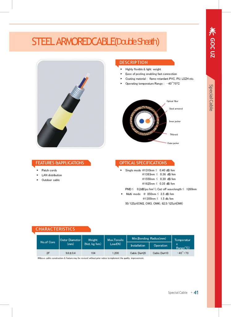
GOC UZSTEEL ARMOREDCABLE(Double Sheath)
DESCRIPTION
Highly flexible & light weight
▶
Ease of peeling enabling fast connection
▶
Coating material : flame retardant PVC, PU, LSZH etc.
▶
Operating temperature Range : -40~70℃
Optical fiber
Steel armored
Inner jacker
TA braid
Outer jacker
FEATURES &APPLICATIONS
OPTICAL SPECIFICATIONS
▶
Patch cords
▶
▶
LAN distribution
▶
Outdoor cable
Single mode @1310nm ≤ 0.40 dB/km
@1383nm ≤ 0.36 dB/km
@1550nm ≤ 0.30 dB/km
@1625nm ≤ 0.35 dB/km
PMD ≤
▶
0.2dB(ps/km½), Cut-off wavelength ≤ 1260nm
Multi mode @ 850nm ≤ 3.5 dB/km
@1300nm ≤ 1.5 db/km
50/125㎛(OM2, OM3, OM4), 62.5/125㎛(OM1)
CHARACTERISTICS
Min.Bending Radius(mm)
No.of Core
Outer Diameter
(mm)
Weight
(Net. kg/km)
Max.Tensile
Load(N)
Installation
Operation
Temperatur
e
Range(℃)
2F
9.8±0.4
104
1,200
Cable Dia*20
Cable Dia*10
-40~+70
#Above cable construction & feature may be revised without prior notice to implement the quality improvement.
Special Cable + 41
Special Cable
▶
29.
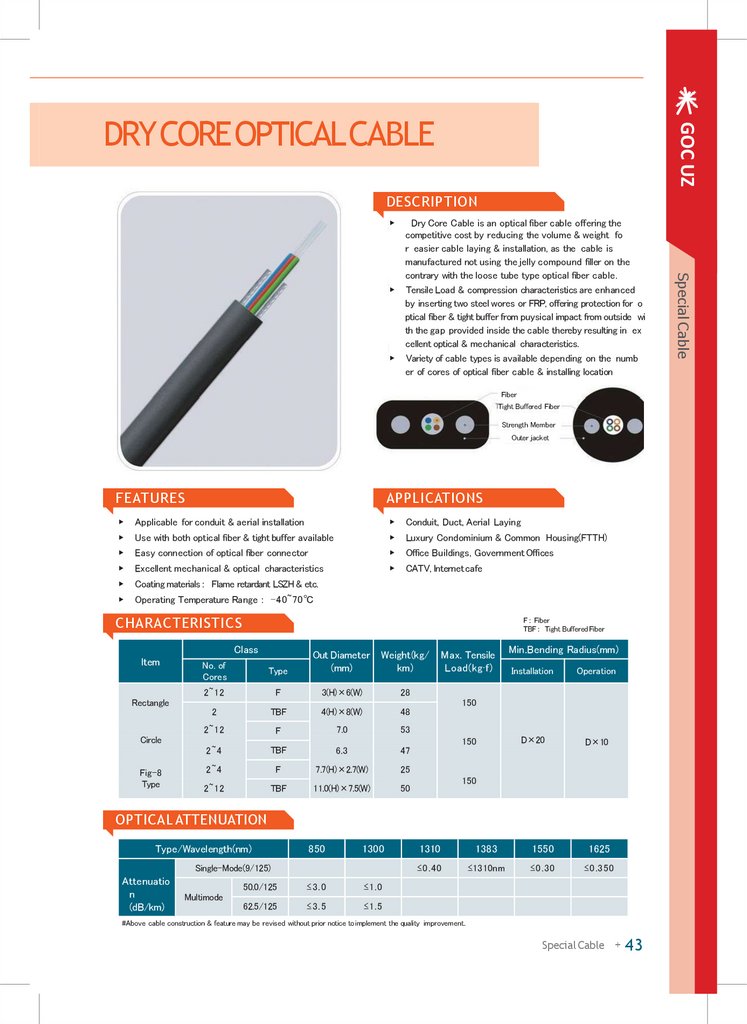
GOC UZDRYCOREOPTICALCABLE
DESCRIPTION
▶
▶
Fiber
Tight Buffered Fiber
Strength Member
Outer jacket
FEATURES
APPLICATIONS
▶
Applicable for conduit & aerial installation
▶
Conduit, Duct, Aerial Laying
▶
Use with both optical fiber & tight buffer available
▶
Luxury Condominium & Common Housing(FTTH)
▶
Easy connection of optical fiber connector
▶
Office Buildings, Government Offices
▶
Excellent mechanical & optical characteristics
▶
CATV, lnternetcafe
▶
Coating materials : Flame retardant LSZH & etc.
▶
Operating Temperature Range : -40~70℃
CHARACTERISTICS
F : Fiber
TBF : Tight BufferedFiber
Class
ltem
Rectangle
No. of
Cores
Type
Out Diameter
(mm)
2~12
F
3(H)×6(W)
28
2
TBF
4(H)×8(W)
48
2~12
F
7.0
53
2~4
TBF
6.3
47
2~4
F
7.7(H)×2.7(W)
25
2~12
TBF
11.0(H)×7.5(W)
50
Circle
Fig-8
Type
Weight(kg/
km)
Max. Tensile
Load(kg·f)
Min.Bending Radius(mm)
Installation
Operation
D×20
D×10
150
150
150
OPTICAL ATTENUATION
Type/Wavelength(nm)
850
1300
Single-Mode(9/125)
Attenuatio
n
(dB/km)
Multimode
50.0/125
≤ 3 .0
≤1.0
62.5/125
≤ 3 .5
≤1.5
1310
1383
1550
1625
≤0.40
≤1310nm
≤0.30
≤0.350
#Above cable construction & feature may be revised without prior notice to implement the quality improvement.
Special Cable + 43
Special Cable
▶
Dry Core Cable is an optical fiber cable offering the
competitive cost by reducing the volume & weight fo
r easier cable laying & installation, as the cable is
manufactured not using the jelly compound filler on the
contrary with the loose tube type optical fiber cable.
Tensile Load & compression characteristics are enhanced
by inserting two steel wores or FRP, offering protection for o
ptical fiber & tight buffer from puysical impact from outside wi
th the gap provided inside the cable thereby resulting in ex
cellent optical & mechanical characteristics.
Variety of cable types is available depending on the numb
er of cores of optical fiber cable & installing location
30.
OPTICAL FIBERCABLESSPECIALITYOPTICALPATCHCORD
DESCRIPTION
▶
▶
Specialty Optical Fiber Jumper Cable is designed
to be suitable for the applications under vulnerable enviro
nments & special purpose applications considering the m
echanical & environmental conditions.
The optical fiber cable provides the special connector a
rrangement on both ends of cable for the ease of cable
laying concenience & connections at emergency situati
ons.
Fiber
Tight Buffered Fiber
Strength Member
Outer jacket
FEATURES
APPLICATIONS
▶
▶
For emergency area, national disaster area & military
applications
▶
▶
For optical fiber cable assembly
Communication terminals or connection between
equipments
▶
▶
▶
▶
Connection of specialty optical fiber connector of
1 ~ 4 core cables
Connector construction of protective cover
connecting section
Ease of handling with compact & light weight
Tubing with Aluminum or Stainless Steel provided
with diverse connector connection availability
Use of cable moving bobbin for easy moving for
emergency application
▶
Coating Materials : Flame retardant LSZH
▶
Operating Temperature Range : -40~70℃
CHARACTERISTICS
D : Outer Diameter
TBF : Tight BufferedFiber
Class
ltem
No. of
Cores
Type
Rectangle
4
TBF
Out Diameter
(mm)
Weight(kg/
km)
Max. Tensile
Load(kg·f)
3(H)×6(W)
25
150
4(H)×8(W)
48
150
40
150
Circle
Min.Bending Radius(mm)
Installation
Operation
D×20
D×10
OPTICAL ATTENUATION
Item
Water proofing
Test(10m)
Contact Test
(500)
Connecting
Attenuation
Temperature
Characteristic
Salt Spray Test
Result
pass
pass
Max.1.0
Max.1.5
Good
Test
◈
◈
◈
Water Proofing Test : 5 min. test on the receptacle & plug sprayed with water from 1.3m distance
Temperature Test Condition : 5 routines under +7℃ for 30min. /-40℃ for 30min.(Total 5hours)
Salt Test : Test inside the Temperatute Chamber for 48hours
(Density-5%, ph6.8, Temperature -35℃, Spray Liquid : 2.4ml/h)
#Above cable construction & feature may be revised without prior notice to implement the quality improvement.
44 + GOC UZ
31.
GOC UZMILITARYTACTICALOPTICALCABLE
DESCRIPTION
▶
Central strength member
Tight buffered fiber
Aramid yarn
Inner jacket
Outer jacket
Rip cord
FEATURES
APPLICATIONS
▶ Ease of handling when laying the cable
(Excellent mechanical characteristics)
▶
Military tactical application
▶
Emergency recovery cable
▶
Ease of handling with flexibility & light weight
▶
Mining, commercial & other risky areas
▶
Similar construction with break out cable
▶
Coating materials : Flame retardant PU & etc.
▶
Operating Temperature Range : -40~70℃
CHARACTERISTICS
No.of Core
Outer Diameter
(mm)
Weight
(Net. kg/km)
Max.Tensile
Load(N)
2
6.5
38
200
4
7.0
45
200
Min.Bending Radius(mm)
Crush(N)
Installation
Operation
DX20
D×10
DX20
OPTICAL ATTENUATION
Type/Wavelength(nm)
850
1300
Single-Mode(9/125)
Attenuatio
n
(dB/km)
50.0/125
≤3.00
≤1.00
62.5/125
≤3.50
≤1.50
1310
1383
1550
1625
≤0.40
≤1310nm
≤0.30
≤0.350
Multimode
#Above cable construction & feature may be revised without prior notice to implement the quality improvement.
Special Cable + 45
Special Cable
▶
Military tactical cable is of construction inserting two or
four optical fiber cords offering application to connector at
tached optical fiber cable as well with ease connection an
d handing of optical fiber cords at the cable ends.
Insertion of 900 ㎛ tight buffer and aramid yarn protects
the optical fiber strengthening the mechanical & environ
mental characteristics.
32.
OPTICAL FIBERCABLESEMERGENCYREPAIRINGOPTICALCABLE
DESCRIPTION
▶
▶
▶
Emergency Recovery Optical Fiber Cable is designed to
conveniently install at the cable laying locations where th
e urgent connections are required prior to the normal rec
overy, by simply coiling on a bobbin after connecting the
common connectors at the both ends of optical fiber cabl
es.
The optical fiber cable is of rectangular dry core constructio
n, provided with strong withstandingperformance against the
external environmental changes and superior mechanical ch
aracteristic.
The cable is guaranteed with in outstanding tensile strength, f
lexibility, torsion characteristics & long term reliability meeting
the application purpose of using under emergency situations.
Fiber
Tight Buffered Fiber
Strength Member
Outer jacket
FEATURES
APPLICATIONS
▶
Excellent tensile strength & flexibility
▶
For Emergency Recovery, LAN
▶
Use of bobbin for ease of cable laying & rewinding
▶
Urgent temporary communication system
▶
Connection with variety of connectors available
▶
For elevator application
▶
Coating materials : Flame retardant PU & etc.
▶
Emergency horizontal & vertical cable laying
▶
Operating Temperature Range : -40~70℃
▶
For tactical military operations
F: Fiber
D: Outer Diameter
TBF: Tight Buffered Fiber
CHARACTERISTICS
Class
ltem
Rectangle
Circle
Type
Out Diameter
(mm)
Weight(kg/
km)
2~12
F
3(H)×6(W)
28
2
TBF
4(H)×8(W)
48
2~12
F
7.0
53
2~4
TBF
6.3
47
No. of
Cores
Max. Tensile
Load(kg·f)
150
Min.Bending Radius(mm)
Installation
Operation
D×20
D×10
OPTICAL ATTENUATION
Type/Wavelength(nm)
850
1300
Single-Mode(9/125)
Attenuatio
n
(dB/km)
Multimode
50.0/125
≤ 3 .0
≤1.0
62.5/125
≤ 3 .5
≤1.5
1310
1383
1550
1625
≤0.40
≤1310nm
≤0.30
≤0.35
#Above cable construction & feature may be revised without prior notice to implement the quality improvement.
46 + GOC UZ
33.
GOC UZHYBRIDCABLE
DESCRIPTION
Access control systems
▶
Airports
▶
Auto and storage lots
▶
Bridges
▶
CCTV video surveillance
▶
Commercial aerospace
Special Cable
▶
Optical fiber
Tight buffer
Strength member
Simplex cord
Water swellable yarn
AWG 16
Central strength member
Water swellable tape
Rip cord
Al shield tape
Outer jacket
FEATURES &APPLICATIONS
OPTICAL SPECIFICATIONS
▶
Connectivity environment : Hybrid Fiber
▶
▶
Optic/Electrical
Single mode @1310nm ≤ 0.40 dB/km
@1383nm ≤ 0.36 dB/km
@1550nm ≤ 0.30 dB/km
@1625nm ≤ 0.35 dB/km
PMD ≤
▶
0.2dB(ps/km½), Cut-off wavelength ≤ 1260nm
Multi mode @ 850nm ≤ 3.5 dB/km
@1300nm ≤ 1.5 db/km
50/125㎛(OM2, OM3, OM4), 62.5/125㎛(OM1)
CHARACTERISTICS
Min.Bending Radius(mm)
No.of Core
Outer Diameter
(mm)
Weight
(Net. kg/km)
Max.Tensile
Load(N)
Installation
Operation
Temperatur
e
Range(℃)
4F
13±0.3
180
1,400
Cable Dia*20
Cable Dia*15
-40~+70
#Above cable construction & feature may be revised without prior notice to implement the quality improvement.
Special Cable + 47
34.
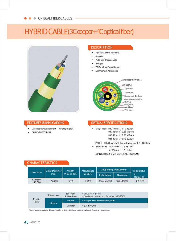
OPTICAL FIBERCABLESHYBRIDCABLE(3Ccooper+4Copticalfiber)
DESCRIPTION
▶
Access Control Systems
▶
Airports
▶
Auto and StorageLots
▶
Bridges
▶
CCTV Video Surveillance
▶
Commercial Aerospace
AWG14(0.26/41), Ф3.5mm
SM G.657b2
Tight buffer
Aramid yarn
Simplex cord Ф3.5mm
Central strength member
Rip Cord
Inner jacket
Aramid yarn
Outer jacket
FEATURES &APPLICATIONS
OPTICAL SPECIFICATIONS
▶
Connectivity Environment : HYBRID FIBER
▶
▶
OPTIC/ELECTRICAL
Single mode @1310nm ≤ 0.40 dB/km
@1383nm ≤ 0.36 dB/km
@1550nm ≤ 0.30 dB/km
@1625nm ≤ 0.35 dB/km
PMD ≤
▶
0.2dB(ps/km½), Cut-off wavelength ≤ 1260nm
Multi mode @ 850nm ≤ 3.5 dB/km
@1300nm ≤ 1.5 db/km
50/125㎛(OM2, OM3, OM4), 62.5/125㎛(OM1)
CHARACTERISTICS
Min.Bending Radius(mm)
No.of Core
Outer Diameter
(mm)
Weight
(Net. kg/km)
Max.Tensile
Load(N)
Installation
Operation
Temperatur
e
Range(℃)
3C copper
+ 4F Fiber
17.0±0.5
340
3.000
Cable Dia*150
Cable Dia*10
-20~+70
Copper wire
IEC60364
Stranded wire
Electric
Power
- 3ea, 0.67/7, 2.5 ㎟
- Conductor resistance : 7.41Ω/km, 450/750V
material
- Halogen Free Reraedant Polyolefin
Diameter
- 3.5 ± 0.2mm
Sheath
#Above cable construction & feature may be revised without prior notice to implement the quality improvement.
48 + GOC UZ
35.
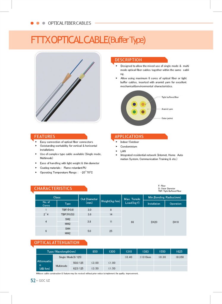
OPTICAL FIBERCABLESFTTXOPTICALCABLE(BufferType)
DESCRIPTION
▶
▶
Designed to allow the mixed use of single mode & multi
mode optical fiber cables together within the same cabli
ng.
Allow using maximum 6 cores of optical fiber or tight
buffer cables, inserted with aramid yarn for excellent
mechanical&environmental characteristics.
Tight buffered fiber
Aramid yarn
Outer jacket
FEATURES
APPLICATIONS
▶
▶
▶
Indoor/Outdoor
▶
Condominium
▶
▶
LAN
Integrated residential network (Internet, Home Auto
mation System, Communication Training & etc.)
▶
Easy connection of optical fiber connectors
Outstanding workability for vertical & horizontal
installations
Use of complex type cable available (Single mode,
Multimode)
▶
Ease of handling with light weight & thin diameter
▶
Coating materials : Flame retardant PU
▶
Operating Temperature Range : -20~70℃
F: Fiber
D: Outer Diameter
TBF: Tight Buffered Fiber
CHARACTERISTICS
Class
No. of
Cores
1
2~4
Type
Out Diameter
(mm)
Weight(kg/km)
TBF(Ф0.9)
3.0
8
TBF(Ф0.53)
3.6
14
3.8
11
5.0
25
SM2
4
MM2
SM4
6
MM2
Min.Bending Radius(mm)
Max. Tensile
Load(kg·f)
Installation
Operation
66
DX20
DX10
OPTICAL ATTENUATION
Type/Wavelength(nm)
850
1300
Single-Mode(9/125)
Attenuatio
n
(dB/km)
Multimode
50.0/125
≤3.00
≤1.00
62.5/125
≤3.50
≤1.50
1310
1383
1550
1625
≤0.40
≤1310nm
≤0.30
≤0.350
#Above cable construction & feature may be revised without prior notice to implement the quality improvement.
52 + GOC UZ
36.
GOC UZFTTXDROPCABLE(Fiber Type)
DESCRIPTION
▶
Indoor/outdoor tight-buffered cable design for use instal
lations requring a flame-retardant, low-smoke and zero
-halogen cable
FTTX Cable
Optical fiber
Buffered
Strength member
Outer jacket
Coloring fiber
Strength member
Outer sheath
FEATURES &APPLICATIONS
OPTICAL SPECIFICATIONS
▶
Suitable for indoor or outdoor applications
▶
▶
Jacket is UV, fungus and moisture resistant
Single mode @1310nm ≤ 0.38 dB/km
@1383nm ≤ 0.36 dB/km
@1550nm ≤ 0.25 dB/km
@1625nm ≤ 0.30 dB/km
PMD ≤
▶
0.2dB(ps/km½), Cut-off wavelength ≤ 1260nm
Multi mode @ 850nm ≤ 3.5 dB/km
@1300nm ≤ 1.5 db/km
50/125㎛(OM2, OM3, OM4), 62.5/125㎛(OM1)
CHARACTERISTICS
No.of Core
Outer Diameter
(mm)
Weight
(Net. kg/km)
1F
3.0±0.1
8.5
2F
3.0±0.1
7.8
4F
3.0±0.1
8.0
6F
3.2±0.1
8.6
Min.Bending Radius(mm)
Max.Tensile
Load(N)
Installation
Operation
Temperatur
e
Range(℃)
800
Cable Dia*15
Cable Dia*10
-20~+70
▶ 1F : buffer type, 2/4/6F : coloring fiber type . Jacket material : Frame retardant polyurethan
#Above cable construction & feature may be revised without prior notice to implement the quality improvement.
FTTX Cable + 53
37.
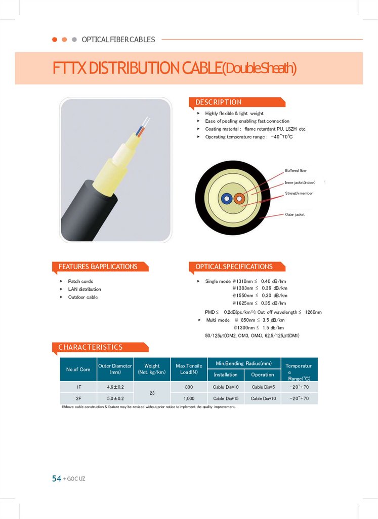
OPTICAL FIBERCABLESFTTXDISTRIBUTIONCABLE(DoubleSheath)
DESCRIPTION
▶
Highly flexible & light weight
▶
Ease of peeling enabling fast connection
▶
Coating material : flame retardant PU, LSZH etc.
▶
Operating temperature range : -40~70℃
Buffered fiber
Inner jacket(indoor)
Strength member
Outer jacket
FEATURES &APPLICATIONS
OPTICAL SPECIFICATIONS
▶
Patch cords
▶
▶
LAN distribution
▶
Outdoor cable
Single mode @1310nm ≤ 0.40 dB/km
@1383nm ≤ 0.36 dB/km
@1550nm ≤ 0.30 dB/km
@1625nm ≤ 0.35 dB/km
PMD ≤
▶
0.2dB(ps/km½), Cut-off wavelength ≤ 1260nm
Multi mode @ 850nm ≤ 3.5 dB/km
@1300nm ≤ 1.5 db/km
50/125㎛(OM2, OM3, OM4), 62.5/125㎛(OM1)
CHARACTERISTICS
No.of Core
Outer Diameter
(mm)
1F
4.6±0.2
Weight
(Net. kg/km)
Min.Bending Radius(mm)
Max.Tensile
Load(N)
Installation
Operation
Temperatur
e
Range(℃)
800
Cable Dia*10
Cable Dia*5
-20~+70
1,000
Cable Dia*15
Cable Dia*10
-20~+70
23
2F
5.0±0.2
#Above cable construction & feature may be revised without prior notice to implement the quality improvement.
54 + GOC UZ
38.
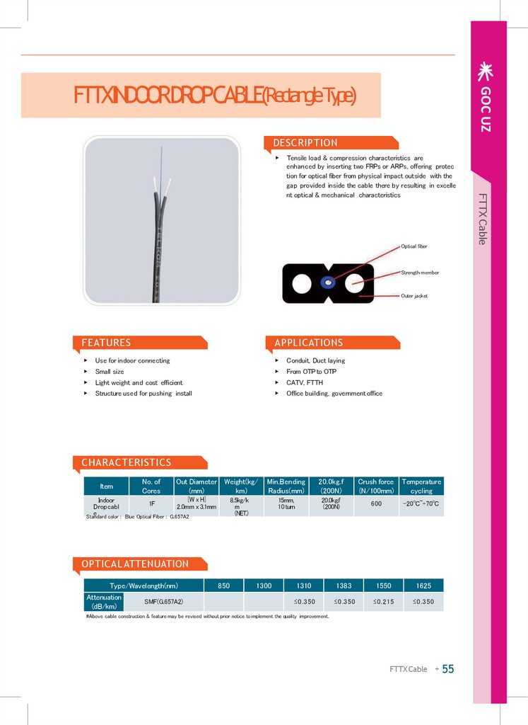
GOC UZFTTXINDOORDROPCABLE(RectangleType)
DESCRIPTION
▶
Optical fiber
Strength member
Outer jacket
FEATURES
APPLICATIONS
▶
Use for indoor connecting
▶
Conduit, Duct laying
▶
Small size
▶
From OTP to OTP
▶
Light weight and cost efficient
▶
CATV, FTTH
▶
Structure used for pushing install
▶
Office building, government office
CHARACTERISTICS
ltem
No. of
Cores
Out Diameter Weight(kg/
(mm)
km)
[W x H]
Indoor
1F
2.0mm x 3.1mm
Dropcabl
e
Standard color : Blue Optical Fiber : G.657A2
Min.Bending
Radius(mm)
20.0kg.f
(200N)
Crush force
(N/100mm)
Temperature
cycling
15mm,
10 turn
20.0kg.f
(200N)
600
-20℃~+70℃
8.5kg/k
m
(NET.)
OPTICAL ATTENUATION
Type/Wavelength(nm)
Attenuation
(dB/km)
SMF(G.657A2)
850
1300
1310
1383
1550
1625
≤0.350
≤0.350
≤0.215
≤0.350
#Above cable construction & feature may be revised without prior notice to implement the quality improvement.
FTTX Cable + 55
FTTX Cable
Tensile load & compression characteristics are
enhanced by inserting two FRPs or ARPs, offering protec
tion for optical fiber from physical impact outside with the
gap provided inside the cable there by resulting in excelle
nt optical & mechanical characteristics
39.
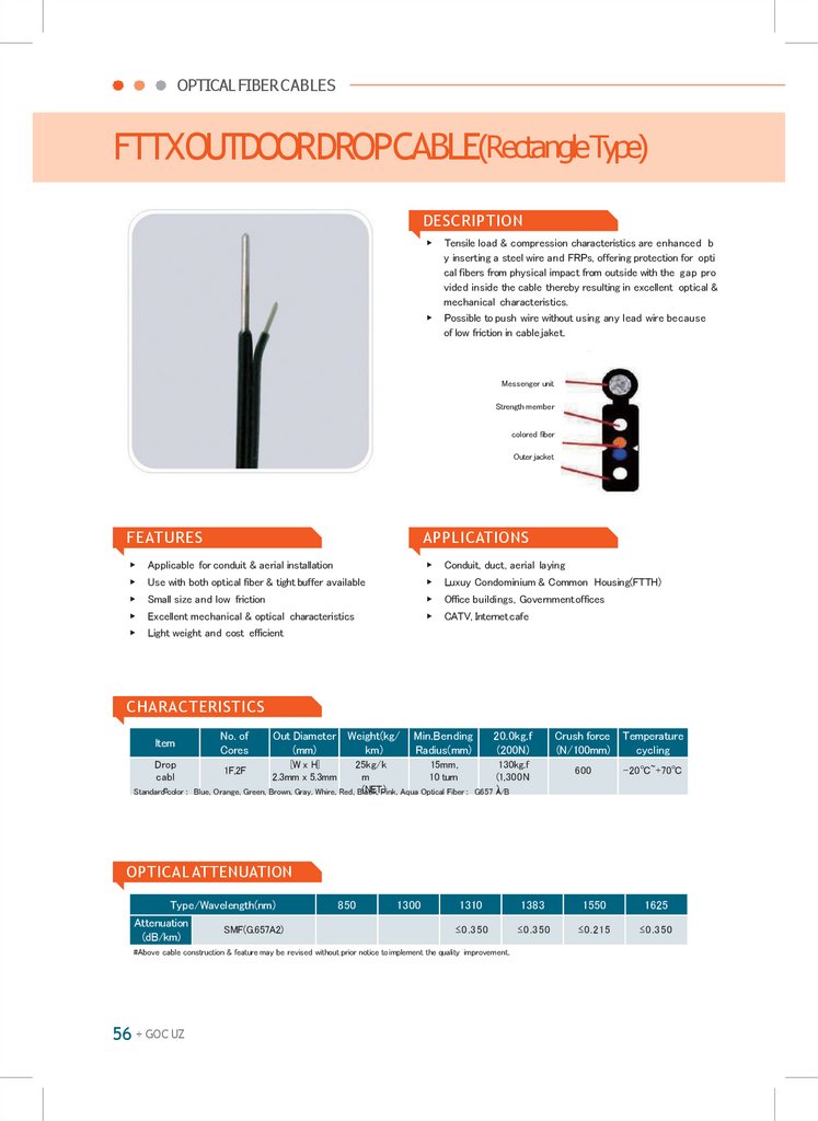
OPTICAL FIBERCABLESFTTXOUTDOORDROPCABLE(RectangleType)
DESCRIPTION
▶
▶
Tensile load & compression characteristics are enhanced b
y inserting a steel wire and FRPs, offering protection for opti
cal fibers from physical impact from outside with the gap pro
vided inside the cable thereby resulting in excellent optical &
mechanical characteristics.
Possible to push wire without using any lead wire because
of low friction in cable jaket.
Messenger unit
Strength member
colored fiber
Outer jacket
FEATURES
APPLICATIONS
▶
Applicable for conduit & aerial installation
▶
Conduit, duct, aerial laying
▶
Use with both optical fiber & tight buffer available
▶
Luxuy Condominium & Common Housing(FTTH)
▶
Small size and low friction
▶
Office buildings, Government offices
▶
Excellent mechanical & optical characteristics
▶
CATV, Internetcafe
▶
Light weight and cost efficient
CHARACTERISTICS
ltem
No. of
Cores
Out Diameter Weight(kg/
(mm)
km)
Min.Bending
Radius(mm)
20.0kg.f
(200N)
[W x H]
Drop
25kg/k
15mm,
130kg.f
1F,2F
cabl
m
10 turn
(1,300N
2.3mm x 5.3mm
(NET.)
)
Standardecolor : Blue, Orange, Green, Brown, Gray, Whire, Red, Black,
Pink, Aqua Optical Fiber : G657 A/B
Crush force
(N/100mm)
Temperature
cycling
600
-20℃~+70℃
OPTICAL ATTENUATION
Type/Wavelength(nm)
Attenuation
(dB/km)
SMF(G.657A2)
850
1300
1310
1383
1550
1625
≤0.350
≤0.350
≤0.215
≤0.350
#Above cable construction & feature may be revised without prior notice to implement the quality improvement.
56 + GOC UZ
40.
GOC UZFig-8TYPEOPTICALCABLE
DESCRIPTION
▶
▶
Messenger wire
Tight buffered fiber
Aramid yarn
Outer jacket
FEATURES
APPLICATIONS
▶
Light weight, compact & ease of handling
▶
LAN
▶
▶
Economical construction for aerial cabling application
Outstanding mechanical & environmental
characteristics
▶
Subscriber network
▶
CATV, PCCafe
▶
Coating materials : Flame retardant LSZH & etc.
▶
Operating Temperature Range: -40~70℃
CHARACTERISTICS
D: Outer Diameter
No. of
Cores
Outer Diameter
(Height x Width)
Weight(kg/km)
Max. Tensile
Load(kg·f)
2
4.7 X 8
27
80
4
4.7 X 8
28
80
6
5.5 X 9
29
80
Min.Bending Radius(mm)
Installation
Operation
DX20
DX10
OPTICAL ATTENUATION
Type/Wavelength(nm)
850
1300
Single-Mode(9/125)
Attenuatio
n
(dB/km)
Multimode
50.0/125
≤3.00
≤1.00
62.5/125
≤3.50
≤1.50
1310
1383
1550
1625
≤0.40
≤1310nm
≤0.30
≤0.350
#Above cable construction & feature may be revised without prior notice to implement the quality improvement.
FTTX Cable + 57
FTTX Cable
▶
Outdoor type Cable purposely manufactured for ease of
cabling between the electric poles or leading into buildin f
rom pole, manufactured with the self standing, "8" shape c
onstruction.
Designed to have the appropriate tensile load considerin t
he cable laying stress and stable Bending characteristic
Offering excellent mechanical & environmental characteri
stics that may occur after the cable laying wor considerin
g the stress &impact from outside and weathe change.
41.
GOC UZABMC(AIR BLOWNMICRO CABLE)
DESCRIPTION
▶
Optical fiber
Jelly compound
PBT loose tube
Water swellable yarn
CSM
Water swellable tape
Rip cord
Outer jacket
(HDPE, core-lock type)
FEATURES &APPLICATIONS
OPTICAL SPECIFICATIONS
▶
▶
▶
▶
High performance components and construction UL Lis
ted in accordance with NEC sections 770.179(b) for use
in vertical runs in building riser shafts or from floor th flo
or
Cable materials are indoor/outdoor : UV, water and
fungus resistant
Wide operating temperature Range : -40~+85℃
Single mode @1310nm ≤ 0.36 dB/km
@1383nm ≤ 0.35 dB/km
@1550nm ≤ 0.22 dB/km
@1625nm ≤ 0.25 dB/km
PMD ≤
▶
0.2dB(ps/km½), Cut-off wavelength ≤ 1260nm
Multi mode @ 850nm ≤ 3.0 dB/km
@1300nm ≤ 1.0 db/km
50/125㎛(OM2, OM3, OM4), 62.5/125㎛(OM1)
CHARACTERISTICS
No.of Core
Outer Diameter
(mm)
Weight
(Net. kg/km)
12F
36
24F
37
36F
6.7±0.2
38
48F
39
72F
47
Min.Bending Radius(mm)
Max.Tensile
Load(N)
Installation
Operation
Temperatur
e
Range(℃)
1,000
Cable Dia*15
Cable Dia*10
-40~+70
#Above cable construction & feature may be revised without prior notice to implement the quality improvement.
FTTX Cable + 59
FTTX Cable
▶
Indoor/outdoor tight-buffered design allows cables to be
installed in intra-building backbone and inter-building co
mpus locations without costly transitions between cabl ty
pes
The construction of the cable allows multi fiber sub cable t
o be routed to multiple locations such as wiring racks and
sets
42.
OPTICAL FIBERCABLESFTTHTransparentStrongBuffer&Rail
DESCRIPTION
▶
Indoor Purpose
▶
Transparent Buffer
▶
Strength Member : Aramid yarn
FEATURES&APPLICATIONS
▶
▶
Single-mode fiber cable
Installation method : fixed by inserting to the
rail
▶
MAX. Tensile Load : 50N
OPTICAL SPECIFICATIONS
▶
Single mode @ 1310nm ≤ 0.36 dB/km
@ 1383nm ≤ 0.35 dB/km
@ 1550nm ≤ 0.22 dB/km
@ 1625nm ≤ 0.25 dB/km
▶
PMD ≤ 0.2dB(ps/km1/2)
▶
Cut-off Wavelength ≤ 1260nm
CHARACTERISTICS
Buffer
diameter(mm
)
Number of Fiber
per tube
Weight
(kg/km)
Max.Tensile load
1F
0.9±0.1
1F /tube
0.7
4kg
1F
1.5±0.1
1F /tube
1.9
4kg
Cores
62 + GOC UZ
43.
GOC UZFTTHFIG-8DISTRIBUTIONCABLE
DESCRIPTION
Single mode, 1 or 2 fibers
▶
Semi Strip Buffer
▶
Reinforced Aramid Yarn
▶
LSZH(FR-PE) Jacket
FTTX Cable
▶
FEATURES&APPLICATIONS
OPTICAL SPECIFICATIONS
▶
Aerial type drop cable
▶
▶
Outdoor cable
▶
Easy Installation
▶
FTTH(Fiber To The Home)
Single mode @ 1310nm ≤ 0.36 dB/km
@ 1383nm ≤ 0.36 dB/km
@ 1550nm ≤ 0.22 dB/km
@ 1625nm ≤ 0.30 dB/km
PMD ≤ 0.2dB(ps/km1/2)
Cut-off wavelength ≤ 1260nm
CHARACTERISTICS
No. of
Core
Outer Diameter(mm)
Weight
(Net.Kg/km)
1F
3.0±0.1*5.8±0.2
20
Max. Tensile
Load(N)
1,300
4F
3.2±0.1*5.9±0.2
Min. Bending Radius(mm) Temperatur
e
Installation
Operation
Range(℃)
D X 20
D X 15
10℃ ~ 70℃
21
FTTX Cable + 63
44.
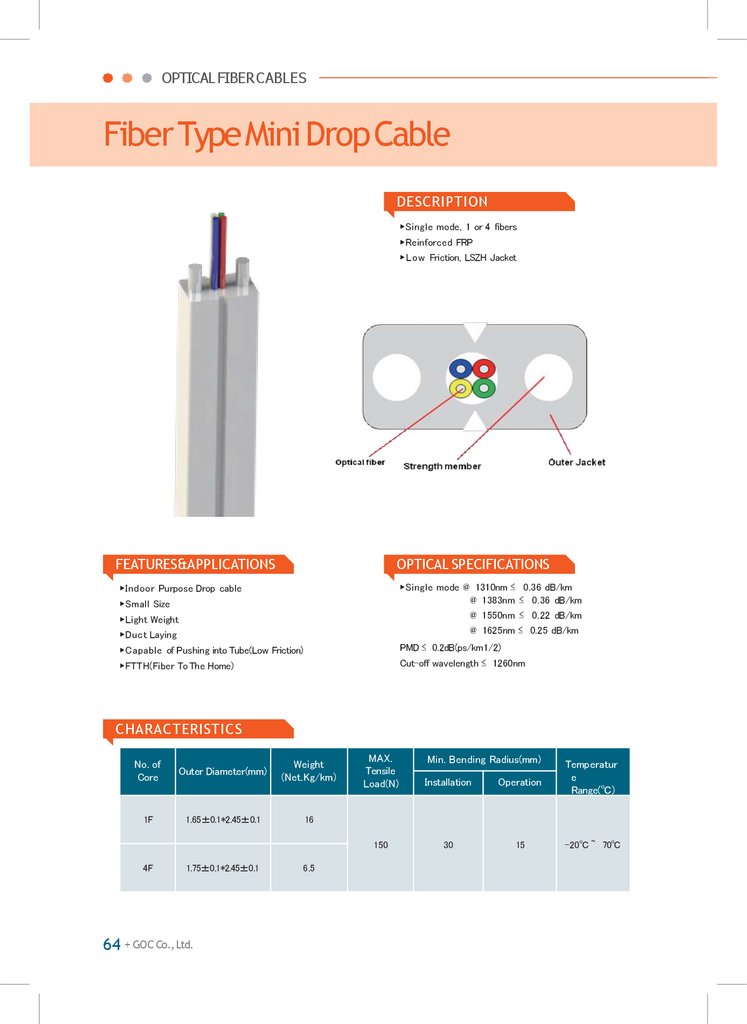
OPTICAL FIBERCABLESFiber TypeMini Drop Cable
DESCRIPTION
▶Single mode, 1 or 4 fibers
▶Reinforced FRP
▶Low Friction, LSZH Jacket
FEATURES&APPLICATIONS
OPTICAL SPECIFICATIONS
▶Indoor Purpose Drop cable
▶Duct Laying
▶Single mode @ 1310nm ≤ 0.36 dB/km
@ 1383nm ≤ 0.36 dB/km
@ 1550nm ≤ 0.22 dB/km
@ 1625nm ≤ 0.25 dB/km
▶Capable of Pushing into Tube(Low Friction)
PMD ≤ 0.2dB(ps/km1/2)
▶FTTH(Fiber To The Home)
Cut-off wavelength ≤ 1260nm
▶Small Size
▶Light Weight
CHARACTERISTICS
No. of
Core
Outer Diameter(mm)
Weight
(Net.Kg/km)
1F
1.65±0.1*2.45±0.1
16
4F
1.75±0.1*2.45±0.1
64 + GOC Co., Ltd.
6.5
MAX.
Tensile
Load(N)
Installation
Operation
150
30
15
Min. Bending Radius(mm)
Temperatur
e
Range(℃)
-20℃ ~ 70℃
45.
FTTxPre-Connectorized PatchCordFTTX Cable
DESCRIPTION
The Pre-Connectorized Drop & Cord cables could be used for the purpose of the transition from Fiber Distribution Ter
minal to the individual living units or Multi Dwelling Units (MDU), and provide quick and easy deployment with the increa
sed reliability. It also allowsfast turn up service and network reach, and lowers maintenance costs
SPECIFICATIONS
Description
UNIT
Specifications
Insertion Loss
dB
≤ 0.3
Return Loss
dB
Cord Length
m
Ordering Customized
Jacketing Color
-
Black
Remarks
≥ 50
UPC
≥ 60
APC
Parts
Structure
Material
colors
Ferrule Cap
Ferrule Protect
CapHousing, Boot
LDPE
UPC: BlueAPC: Green
UPC
Zirconia Ceramic
White
APC
Zirconia Ceramic
WhiteAngle:8°±0.3
Plug Frame
SC Type
PBT
White
Stopper Frame
SC Type
PBT
White
-
Steel
-
Ferrule
Remarks
FTTX Cable + 65
46.
OPTICAL FIBERCABLESFan-OutTypePLC SPLITTER1(2×)N
PLC (planar lightwave circuit) splitter is fabricated by using silica optical w
aveguide technology. It features wide operating wavelength range,
good channel-to-channel uniformity, high reliability and small size, and is wid
ely used in PON networks to realize optical signal power management. We pr
ovide a whole series of 1 x N splitters that are tailored for specific applications.
All products meet Telcordia 1209 and 1221 reliability requirements and are cer
tified by TLC for network development requirement.
GOC can provide customized designs to meet specialized applications, and
also offer modulars assemblies that integrated other components to form a full
function module.
APPLICATIONS
▶
FTTX Solutions
▶
Passive Optical Network(PON)
FURCATIONDIMENSTION(mm)
Dimension(nm)
1x2
1x4
1x8
1x16
1x32
1x64
L
40
40
50
50
55
55
W
4
4
7
7
7
13
H
4
4
4
4
4
4
■ Parameter for 1xNPLC Splitter(Without Connector)
PARAMETER
1x2
1x4
1x8
1x16
1x32
Insertion Loss(dB)
≤3.7
≤7.2
≤10.5
≤13.5
≤16.5
Uniformity(dB)
≤0.6
≤ 0 .6
≤0.8
≤1.2
≤1.7
PDL(dB)
≤0.2
≤ 0 .3
≤0.3
≤ 0 .3
≤ 0 .3
Return Loss(dB)
≥ 55
Directivity(dB)
≥ 55
Operating Wavelength(nm)
1260 ~
1360nm & 1450 ~ 1650nm
Oprating Temperature(℃)
-40℃ ~ 85℃
Humidty Range
5% to 85% RH
66 + GOC UZ
47.
GOC UZFan-OutTypePLCSPLITTER1(2×)N
Optical PLC Splitter
PLC
XXX
XXX
X
XX
XX
X
Input&Output
Input Tube Type
L1 length
L2 length
Count
9=90mm Tight
buffer
12=1.2m
12=1.2m
0=Nome
0=None
104=1X4
Fiber
15=1.5m
15=1.5m
FC/PC
FC/PC
.........
2=Ø2.0mm Fiber
150=15m
150=15m
AFC=FC/APC
AFC=FC/APC
208=2X8
3=Ø3.0mm Fiber
.........
.........
SC/PC
SC/PC
ASC=SC/APC
ASC=SC/APC
Others
Others
Input Connector Output Connector
■ Parameter for 2xNPLC Splitter(Without Connector)
PARAMETER
2x2
2x4
2x8
2x16
2x32
2x64
Insertion Loss(dB)
≤ 3 .9
≤7.5
≤10.8
≤14.1
≤17.4
≤21
Uniformity(dB)
≤ 0 .8
≤1.2
≤1.5
≤ 2 .0
≤ 2 .5
≤ 2 .5
PDL(dB)
≤ 0 .2
≤ 0 .3
≤0.4
≤ 0 .4
≤ 0 .4
≤ 0 .4
Optical PLC Splitter + 67
48.
OPTICAL FIBERCABLESINTERGRATEDTYPEPLC SPLITTER1×N
PLC (planar lightwave circuit) splitter is fabricated by using silica optical
waveguide technology. It features wide operating wavelength range, good ch
annel-to-channel uniformity, high reliability and small size, and is widely used
in PON networks to realize optical signal power management. We provide a w
hole series of 1 x N and 2 x N splitters that are tailored for specific application
s. All products meet Telcordia 1209 and 1221 reliability requirements and are
certified by TLC for network development requirement.
GOC can provide customized designs to meet specialized applications, and
also offer modulars assemblies that integrated
other components to form a full function module.
APPLICATIONS
SPLITTER STAINLESSBAR
▶
FTTX Solutions
▶
Passive Optical Network(PON)
■ Parameter for 1xNPLC Splitter(Without Connector)
PARAMETER
1x2
1x4
1x8
1x16
1x32
Insertion Loss(dB)
≤3.7
≤7.2
≤10.5
≤13.5
≤16.5
Uniformity(dB)
≤ 0 .6
≤ 0 .6
≤ 0 .8
≤1.2
≤1.7
PDL(dB)
≤ 0 .2
≤ 0 .3
≤ 0 .3
≤ 0 .3
≤ 0 .3
Return Loss(dB)
≥ 55
Directivity(dB)
≥ 55
Operating Wavelength(nm)
1260 ~
1360nm & 1450 ~ 1650nm
Oprating Temperature(℃)
-40℃ ~ 85℃
Humidty Range
5% to 85% RH
DIMENSION FOR PLC BAR
Dimension(nm) 1x2
PLC
XXX
XXX
X
XX
XX
X
L1 length
L2 length
Input Connector
Output
Connecto
r
9=90mm
bufferTight
12=1.2m
12=1.2m
0=Nome
0=None
104=1X4
Fiber
15=1.5m
15=1.5m
FC/PC
FC/PC
.........
2=Ø2.0mm
Fiber
150=15m
150=15m
AFC=FC/APC
AFC=FC/APC
208=2X8
3=Ø3.0mm
Fiber
.........
.........
SC/PC
SC/PC
ASC=SC/APC
ASC=SC/APC
Others
Others
Input&Output
Input Tube Type
Count
68 + GOC UZ
1x4
1x8 1x16 1x32
L
60
60
60
60
80
W
7
7
7
12
20
H
4
4
4
4
6
SCHEMATIC DIAGRAM
49.
GOC UZBOXTYPEPLC SPLITTER1(2)×N
Optical PLC Splitter
PLC (planar lightwave circuit) splitter is fabricated by using silica optical waveg
uide technology. It features wide operating wavelength range, good channelto-channel uniformity, high reliability and small size, and is widely used in PO
N networks to realize optical signal power management. We provide a whole s
eries of 1 x N and 2 x N splitters that are tailored for specific applications. All p
roducts meet Telcordia 1209 and 1221 reliability requirements and are certifie
d by TLC for network development requirement.
GOC can provide customized designs to meet specialized applications, and
also offer modulars assemblies that integrated other components to form a full
function module.
APPLICATIONS
▶
FTTX Solutions
▶
Passive Optical Network(PON)
PLC-BOX
Unit(mm)
Fan-out cable
L(mm) W(mm) H(mm) A(mm) B(mm)
1(2) x 2-8
0.9mm or 2.0mm
100
80
10
70
73
1(2) x 16-32
0.9mm
120
80
18
80
74
1(2) x 16
2.0mm
120
80
18
80
74
1(2) x 32
2.0mm
140
115
18
100
106
1(2) x 64
0.9mm or 2.0mm
140
115
18
100
106
XXX
XXX
X
XX
XX
X
Input&Output
Input Tube Type
L1 length
L2 length
Count
9=90mm Tight
buffer
12=1.2m
12=1.2m
0=Nome
0=None
104=1X4
Fiber
15=1.5m
15=1.5m
FC/PC
FC/PC
.........
2=Ø2.0mm Fiber
150=15m
150=15m
AFC=FC/APC
AFC=FC/APC
208=2X8
3=Ø3.0mm Fiber
.........
.........
SC/PC
SC/PC
ASC=SC/APC
ASC=SC/APC
Others
Others
Input Connector Output Connector
Optical PLC Splitter + 69
50.
OPTICAL FIBERCABLESFIELD INSTALLABLECONNECTOR
INTRODUCTION
The Field Installable Connector is cost-effective, and is designed for reusage, ease of installation, optical attenuation from 1d
B to 20dB, and Fiber Bragg Grating (FBG) for fiber monitoring system.
FIC requires no field polishing or epoxy, so no heat cure devices or special tooling are needed to terminate the fiber. It ta
kes about one to two minutes per fiber to install a connector out in the field.
Specifications for GSCand GLC
PARAMETER
SM : SC/PC, LC/PC
MM : SC/PC, LC/PC
Fiver Type
Single Mode : 9/125 ㎛
Multi Mode : 50/125㎛, 62.5//125㎛
Insertion Loss
Max. ≤ 0 . 5 dB
Avg. ≤ 0 . 3 dB
Max. ≤ 0 . 5 dB
Avg. ≤ 0 . 3 dB
Reflectance
≥
40-50 dB(PC/UPC), ≥ 50-60 dB(APC)
Operational Temperature
- 40 ~ 75℃
Storage Temperature
- 40 ~ 80℃
Tensile Load
3N Load ≤ 0.2 dB Change(0.9mm cable)
30N Load ≤ 0.2 dB Change(2.0/3.0mm cable)
70 + GOC UZ
51.
GOC UZFIBER OPTICALPATCHCORD
Accessory
FEATURES
APPLICATIONS
▶
Low insertion loss
▶
Fiber optic telecommunications
▶
High return loss
▶
Optical network equipments
▶
Various connector type available
▶
FTTH
▶
100% in-house tested
▶
CATV, IPTV
▶
High speed transmission system
TECHNICALSPECIFICATIONS
Fiber Mode
Single Mode
Multi Mode
Type
FC, SC, ST, LC, MU
FC, SC, ST, LC, MU
Ext. Diameter (mm)
0.9, 2.0, 3.0
0.9, 2.0, 3.0
Ferrule Type
PC
APC
PC
Insertion Loss (dB)
≤ 0.3
≤ 0.3
≤ 0.3
Return Loss (dB)
≥ 55
≥ 60
-
Operation Temperature(℃)
- 40 ~ 7 5
Storage Temperature(℃)
- 55 ~ 85
Accessory + 71
52.
OPTICAL FIBERCABLESACCESSTERMINAL BOX
INTRODUCTION
GOC has designed Access Terminal Box(ATB) to protect and funcation as a terminal for fiber optic drop cable and/or pat
ch cords in the FTTH Networks. ATB is compact and cost-effective, and being used for the Indoor closure.
This ATB accepts the field-installable connector, fusion splice, and 1×4 splitter and 1×4 coupler for termination.
FEATURES
- Compact design for installation on the wall as well as inside the terminal panel.
- Two screw mounting holes are compatible with the size of the wall switch and telephone box.
- This box protects drop cable and other related optical fiber connection from accidentaldamage.
- Two inner holders retain up to two fusion splice sleeves or splitters/couplers.
- Inner storage area allows the minimum bend radius to prevent micro bends and attenuation.
- Two adapter slots allows up to two SC Type duplex adapters.
- Removable cover is designed for easy access.
TECHNICALSPECIFICATIONS
72 + GOC UZ
PARAMETER
VALUE
Dimension(mm)
117×88×29
Weight(g)
75
Cable Count
1
Adapte
2 Duplex SC Adapter max.
Connection Type
Fusion splice, mechanical splice or field assembly connector
53.
GOC UZAerialJointClosure (Ventilationtype)
Accessory
DESCRIPTION
▶
1 X 8ch : 2ea, 1ⅹ16ch : 1ea optical splitter / 16 SC adapters can be mounted
▶
16 drop cables(2.0mm*3.0mm) can be connected
▶
Passed humidity test : 2days, 55℃ / 90~96R.H
▶
IEC68-2-10 / 20 / 52
▶
IP 65 protection level
SPECIFICATIONS
Box Material
PP+Fiberglass
Size(mm)
670*160*70
Fiber Tray
Capacity
16
Weight(kg)
2.0-2.5
PACKING
Type
Name
GPJ09-9403
Ventilation type aerial joint Closure
Accessory + 73
54.
OPTICAL FIBERCABLESAerialTypeFiberOpticTerminalBox
DESCRIPTION
▶
1ⅹ16 optical splitters and 16 SC adapters can be mounted
▶
16 drop cables can be connected
▶
Protection Class IP55
SPECIFICATIONS
Box material
PP+Fiberglass
Size(mm)
600*153*73
Fiber tray
capacity
24
Weight(kg)
1.8-2.5
PACKING
74 + GOC UZ
Type
Name
GPJ09-9402
Optical Fiber Cable Connector Box
55.
GOC UZPoleTypeFiberOpticDistribution Box
Accessory
DESCRIPTION
▶
Installation / fixing method: wall-mounting or pole-mounting
▶
▶
The maximum fiber capacity: 16 fibers
Features : Fiber Optic Distribution Box could be used for the protection of the branch cables from the feeder ca
ble in building in FTTH of PON technology
SPECIFICATIONS
Box Material
high strength engineeringplastics ABS
Appearance
size(mm)
292 X 248 X 100
Fiber tray
capacity
16fibers2×1:8 PLC splitters and
1×1:16 PLC
Weight(kg)
2.5
PACKING
Type
Name
GF6-15N6S
Pole type Fiber Optic Distribution Box
Accessory + 75
56.
OPTICAL FIBERCABLESOptical DistributionCabinet(ODC)
DESCRIPTION
▶
Installation / Fixing method: Bottom-mounting.
▶
Maximum Fiber Capacity ; 144 & 288 fibers
▶
Features
ODC is an intermediaclosure(housing) dividing a feeder cableinto the distribution c
ables. It is installed on the ground, and branched out by using splitter inside Feede
r cable could obtain up to 144 cores or 288 cores. It satisfies waterproof characteri
stics.
SPECIFICATIONS
12F splicing & distribution tray
Fiber tray
capacity
24F splicing & distribution tray
PACKING
76 + GOC UZ
Type
Name
GODC-144
GOC Optical Distribution Cabinet 144F
GODC-288
GOC Optical Distribution Cabinet 288F
57.
GOC UZFIBER OPTICCABLECLAMP
FEATURES
▶
Use to support messenger drop cable between the pole and house
▶
Accept 3.0mm diameter fiber optic drop cable
▶ Suitable for usage with most one and two pair drop cables
Stainless steel tail wire, plastic(PVC) body
▶
RoHS compliant
▶
Mechanical (tensile) strength exceeds 50kg
▶
Patented
Accessory
▶
TECHNICALSPECIFICATIONS
Size
220mm(L)x20mm(H)x40mm(W)
Bending Radius Allowance
>25mm
Tensile Load
50kgf
Material for Tail wire
STS-304
Material for Body
PVC
Operational Temperature
-30 ~ 40℃
Accessory + 77
58.
OPTICAL FIBERCABLESS-TYPEFASTENER
DESCRIPTION
Binding or Pole self-supporting FTTH drop cable, then pull the cable
with the supporting device. (Material:304stainless steel wire, fire-retardant ABS plastic parts)
SPECIFICATIONS
Box Material
304stainless steel wire, fire-retardant
ABS plastic parts
Appearance
size(mm)
135*23*12
COLOR
BLACK
Weight(kg)
0.03
PACKING
78 + GOC UZ
Type
Name
FTTH S-TYPE FASTENER
S-TYPE fastener
59.
GOC UZC-TYPE WIRERETRACTOR
Accessory
DESCRIPTION
Use the screw to install the C-Type wire retractor on the outer wall of buildings, and connect the S type fastener to con
nect and fix the Self-supporting Optical Fiber Cable
SPECIFICATIONS
Material
3.0mm cold-rolled sheet
Appearance
size(mm)
54*54*35
Surface
finishing
cold galvanizing
Weight(kg)
0.054
PACKING
Type
Name
Wire Retractor
C-typeWire Retractor
Accessory + 79
60.
OPTICAL FIBERCABLESOPTICAL CONNECTORPLIER
(OpticalConnectorExtraction Tool)
FEATURES
▶
▶
Design for ease of use with one hand
Safe and easy installation and removal of each type optical
connectors
▶
Excellent performance in areas of populated connections
▶
Accident Prevention from worket's carelessness
▶
High Reliability and Stability
PRODUCT LIST
80 + GOC UZ
Item No.
Connector Type
CP-1
SC Type only
CP-2
SC/LC Type
61.
DOMESTICDomestic jolee@goc2001.com
GOCkyle
(Headquarters
& Main Factory)
@goc2001.com
Overseas
10, Cheomdan venture-ro 60beon-gil, Buk-gu,
Gwangju, 61009 South Korea
Tel : +82-62-973-6114
Fax : +82-62-973-6116
E-mail : csji@goc2001.com
GOC (Pangyo Sales Office)
U-Space2 B#1008-1, 670, Daewangpangyo-ro, Bundanggu, Seongnam-si, Gyeonggi-do, 13494 South Korea
Tel : +82-31-781-6115
Fax : +82-31-781-6116
Domestic sales : jolee@goc2001.com
Overseas sales : kyle@goc2001.com
E-mail cdi@goc2001.com
Accessory + 81
62.
OVERSEASHeadOffice& South Korea Plant
10. Cheomdan venture-ro
60beon-gil,
500-470,
INTI-GOC
(Joint
Factory)
Buk-gu,
Gwangju,500-470,
61009,
SouthVenture
Korea
TelJL.
+82-62-973-6114
Moch. Toha No.225 Pasawahan, Kec. Dayeuhkolot,
Fax +82-62-973-6116
Bandung,
Indonesia
@goc2001.com
Domestic
jolee40258
Overseas kyle@goc2001.com
Tel : +62-22-520-6510
Fax : +62-22-520-4010
E-mail : jeon@goc2001.com
GOCI (Jakarta Sales Office)
Wisma Kodel Lt 8, Jl. H. R. Rasuna Said, KAV. B-4
Setia Budi, Kota Jakarta Selatan, Daerah Khusus
Ibukota, Jakarta, 12920 Indonesia
Tel : +62-21-522-2266
E-mail : sjpark@goc2001.com
TELGO (Joint Venture Factory)
Rua das Poças - 4455-186 LAVRA | Matosinhos,
Portugal
E-mail : kyle@goc2001.com
GOC-UZ (Joint Venture Factory)
HangzhouGOTOpticalCommunicationCo.,Ltd.
Industrial Zone "A“, Jizzakh region, Jizzakh City,
608# GolfRoad,DongzhouTown,Fuyang City,Zhejiang
Republic of Uzbekistan
China
Tel +86-571-63167319
E-mail : yangij@goc2001.com
Fax +86-571-63373008
E-mail cdi@goc2001.com
jdj@goc2001.com
Accessory + 82