
 industry
Similar presentations:


MS8600S OZON Up Kit Install Manual
1.
MS8600S OZON, Up Kit Install Manual2025.07.15
2.
Revision HistoryRev.
00
Date
WRT
2025.07.15 S.S.JEONG
CHK
APL
Contents
MS8600S, OZON Up Kit ASSEMBLY MANUAL
2 / 23
3.
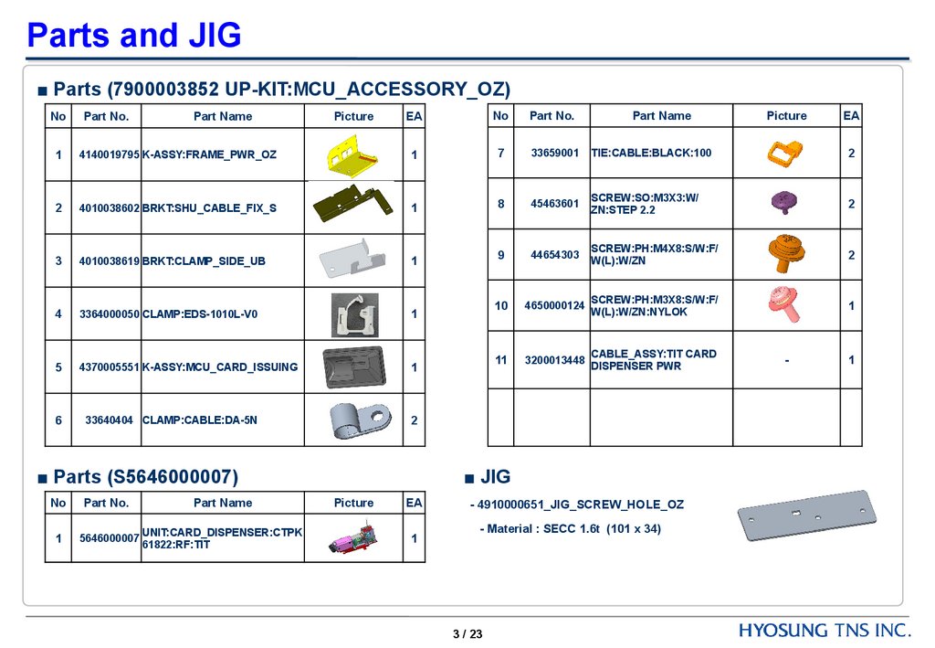
Parts and JIG■ Parts (7900003852 UP-KIT:MCU_ACCESSORY_OZ)
EA
No
Part No.
4140019795 K-ASSY:FRAME_PWR_OZ
1
7
33659001
TIE:CABLE:BLACK:100
2
2
4010038602 BRKT:SHU_CABLE_FIX_S
1
8
45463601
SCREW:SO:M3X3:W/
ZN:STEP 2.2
2
3
4010038619 BRKT:CLAMP_SIDE_UB
1
9
44654303
SCREW:PH:M4X8:S/W:F/
W(L):W/ZN
2
4
3364000050 CLAMP:EDS-1010L-V0
1
10
4650000124
SCREW:PH:M3X8:S/W:F/
W(L):W/ZN:NYLOK
1
5
4370005551 K-ASSY:MCU_CARD_ISSUING
1
11
3200013448
CABLE_ASSY:TIT CARD
DISPENSER PWR
6
33640404 CLAMP:CABLE:DA-5N
2
No
Part No.
1
Part Name
Picture
■ Parts (S5646000007)
No
Part No.
Part Name
1
5646000007
UNIT:CARD_DISPENSER:CTPK
61822:RF:TIT
Part Name
■ JIG
Picture
EA
1
- 4910000651_JIG_SCREW_HOLE_OZ
- Material : SECC 1.6t (101 x 34)
3 / 23
Picture
-
EA
1
4.
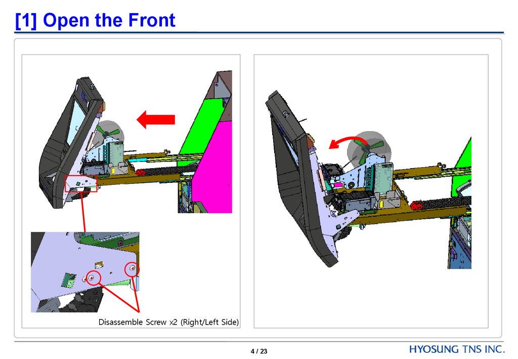
[1] Open the FrontDisassemble Screw x2 (Right/Left Side)
4 / 23
5.
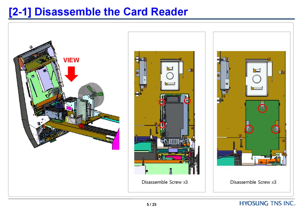
[2-1] Disassemble the Card ReaderVIEW
Disassemble Screw x3
5 / 23
Disassemble Screw x3
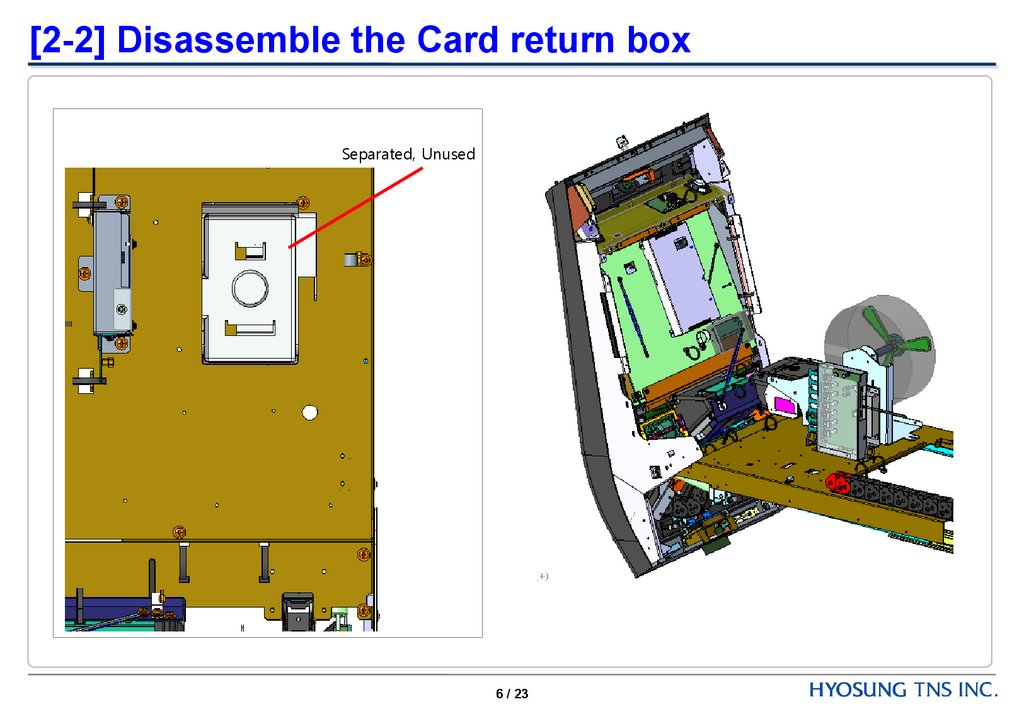
6.
[2-2] Disassemble the Card return boxSeparated, Unused
6 / 23
7.
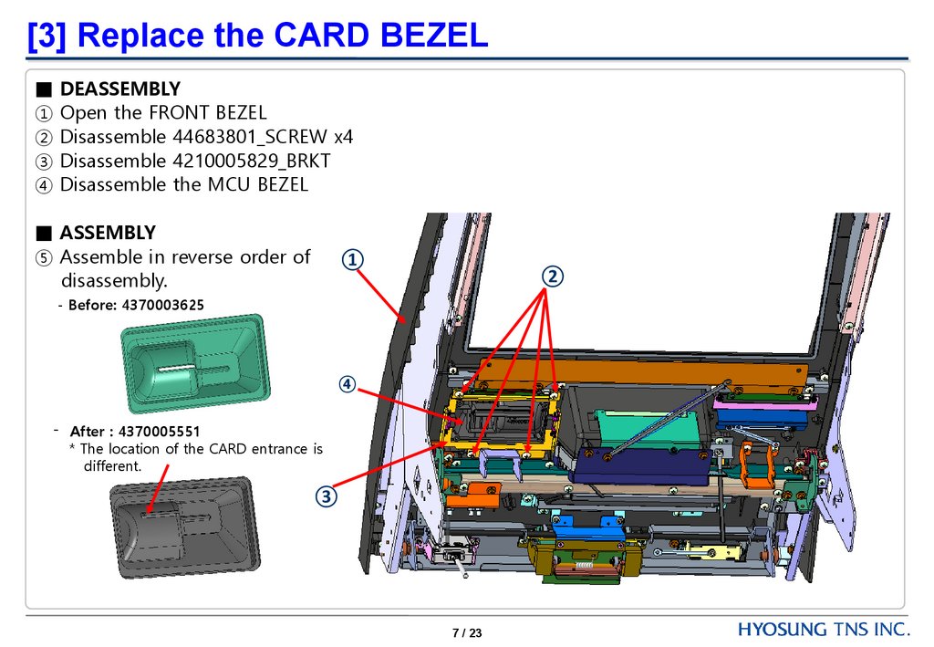
[3] Replace the CARD BEZEL■ DEASSEMBLY
① Open the FRONT BEZEL
② Disassemble 44683801_SCREW x4
③ Disassemble 4210005829_BRKT
④ Disassemble the MCU BEZEL
■ ASSEMBLY
⑤ Assemble in reverse order of
disassembly.
①
②
- Before: 4370003625
④
- After : 4370005551
* The location of the CARD entrance is
different.
③
7 / 23
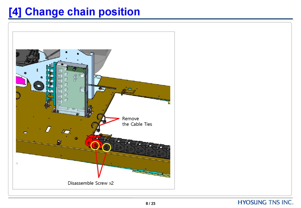
8.
[4] Change chain positionRemove
the Cable Ties
Disassemble Screw x2
8 / 23
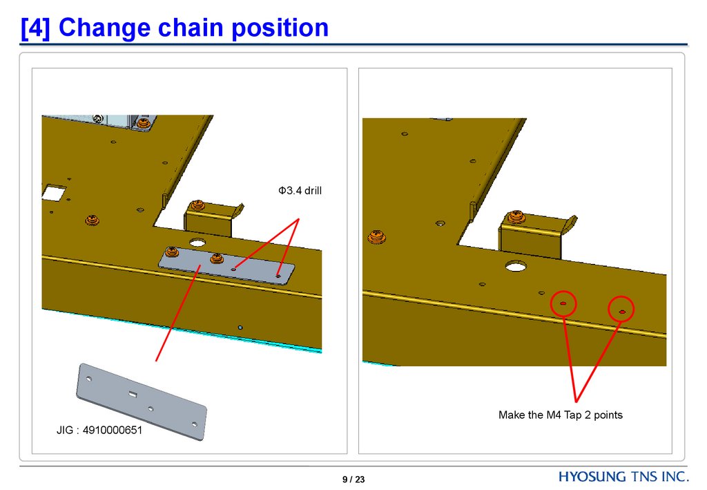
9.
[4] Change chain positionФ3.4 drill
Make the M4 Tap 2 points
JIG : 4910000651
9 / 23
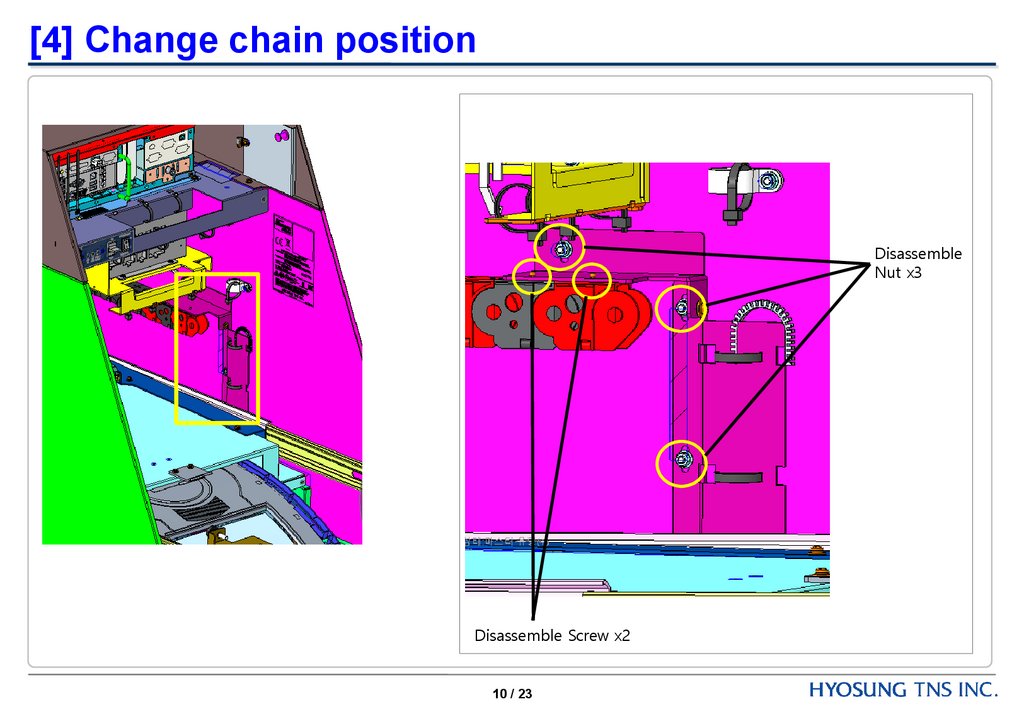
10.
[4] Change chain positionDisassemble
Nut x3
Disassemble Screw x2
10 / 23
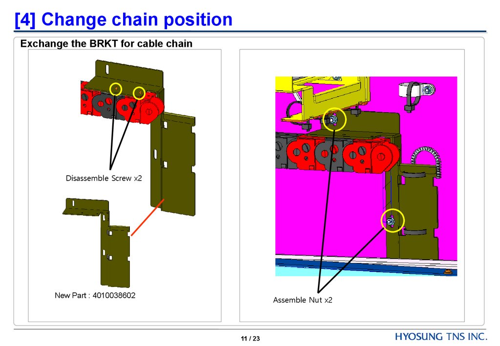
11.
[4] Change chain positionExchange the BRKT for cable chain
Disassemble Screw x2
New Part : 4010038602
Assemble Nut x2
11 / 23
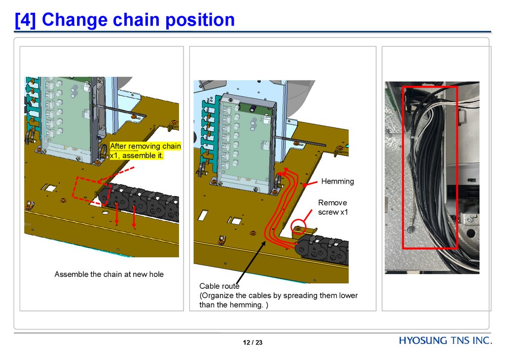
12.
[4] Change chain positionAfter removing chain
x1, assemble it.
Hemming
Remove
screw x1
Assemble the chain at new hole
Cable route
(Organize the cables by spreading them lower
than the hemming. )
12 / 23
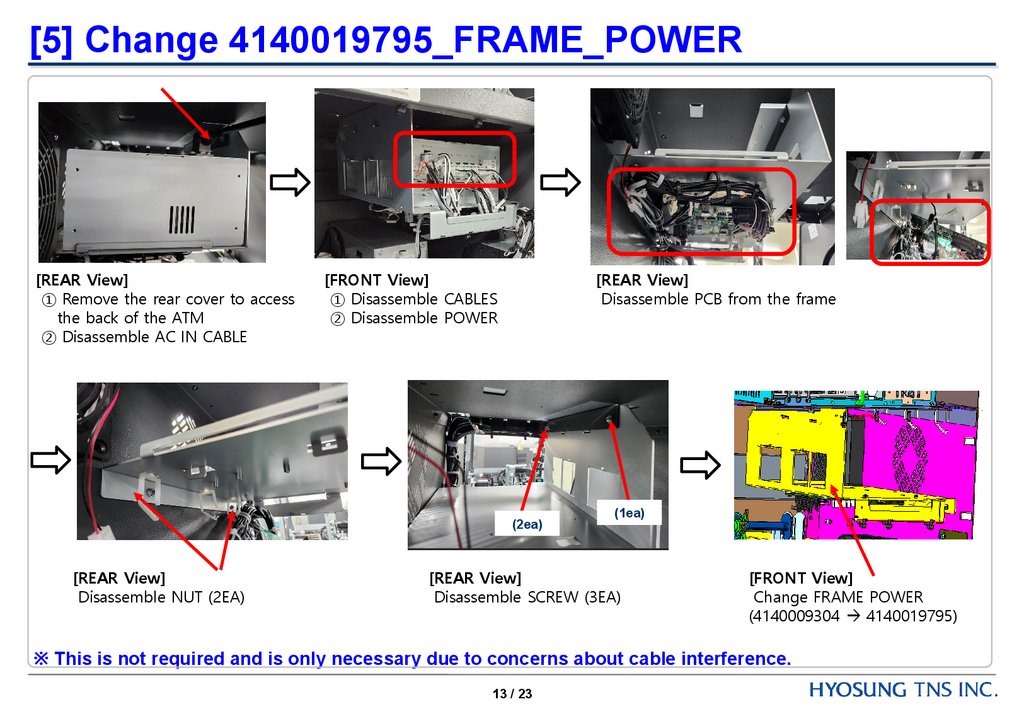
13.
[5] Change 4140019795_FRAME_POWER[REAR View]
① Remove the rear cover to access
the back of the ATM
② Disassemble AC IN CABLE
[FRONT View]
① Disassemble CABLES
② Disassemble POWER
[REAR View]
Disassemble PCB from the frame
(2ea)
[REAR View]
Disassemble NUT (2EA)
(1ea)
[REAR View]
Disassemble SCREW (3EA)
[FRONT View]
Change FRAME POWER
(4140009304 4140019795)
※ This is not required and is only necessary due to concerns about cable interference.
13 / 23
14.
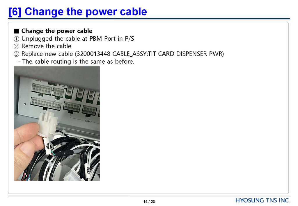
[6] Change the power cable■ Change the power cable
① Unplugged the cable at PBM Port in P/S
② Remove the cable
③ Replace new cable (3200013448 CABLE_ASSY:TIT CARD DISPENSER PWR)
- The cable routing is the same as before.
14 / 23
15.
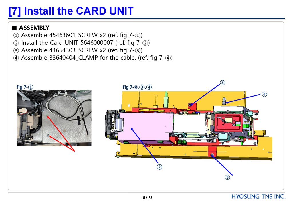
[7] Install the CARD UNIT■ ASSEMBLY
① Assemble 45463601_SCREW x2 (ref. fig 7-①)
② Install the Card UNIT 5646000007 (ref. fig 7-②)
③ Assemble 44654303_SCREW x2 (ref. fig 7-③)
④ Assemble 33640404_CLAMP for the cable. (ref. fig 7-④)
fig 7-①
③
fig 7-②,③,④
④
②
③
15 / 23
16.
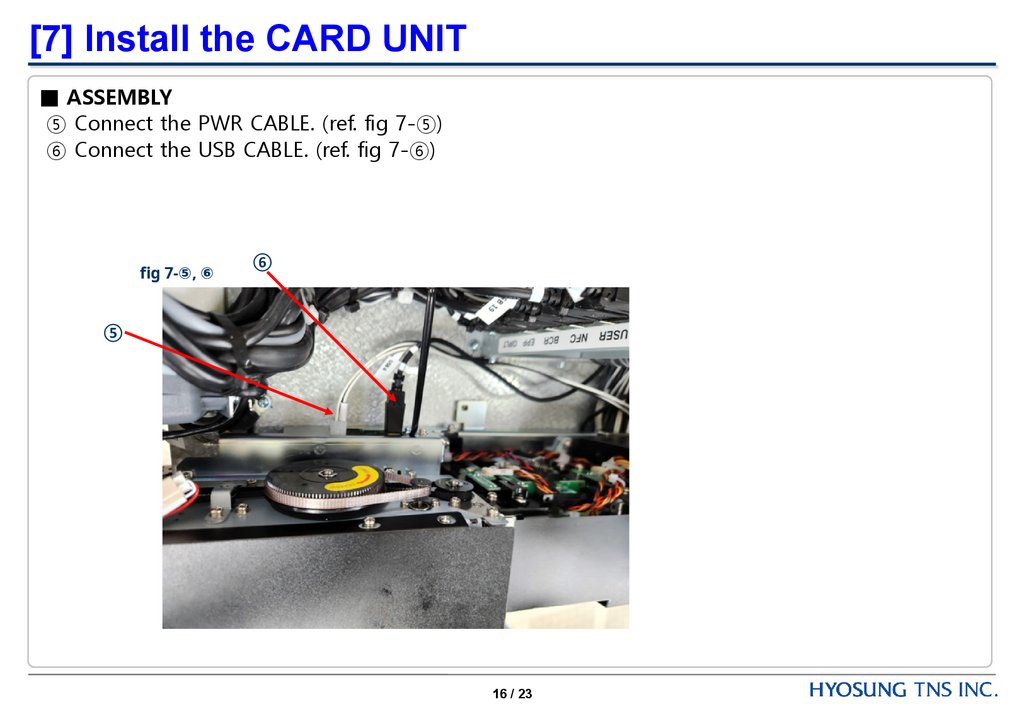
[7] Install the CARD UNIT■ ASSEMBLY
⑤ Connect the PWR CABLE. (ref. fig 7-⑤)
⑥ Connect the USB CABLE. (ref. fig 7-⑥)
fig 7-⑤, ⑥
⑥
⑤
16 / 23
17.
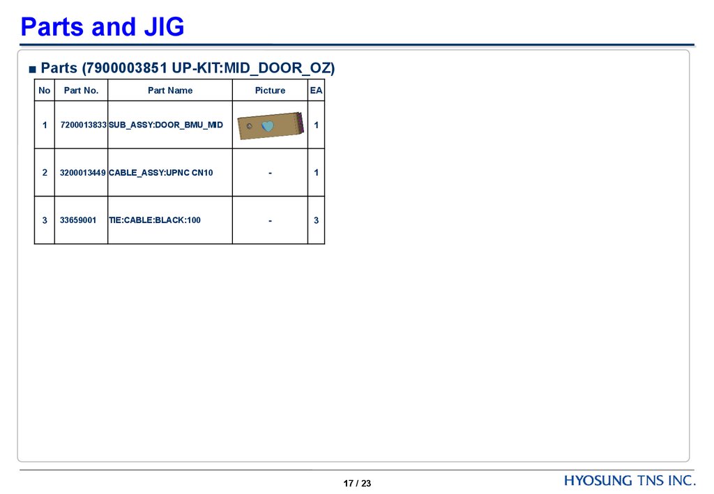
Parts and JIG■ Parts (7900003851 UP-KIT:MID_DOOR_OZ)
No
Part No.
Part Name
1
7200013833 SUB_ASSY:DOOR_BMU_MID
2
3200013449 CABLE_ASSY:UPNC CN10
-
1
3
33659001
-
3
TIE:CABLE:BLACK:100
Picture
EA
1
17 / 23
18.
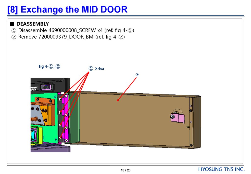
[8] Exchange the MID DOOR■ DEASSEMBLY
① Disassemble 4690000008_SCREW x4 (ref. fig 4-①)
② Remove 7200009379_DOOR_BM (ref. fig 4-②)
fig 4-①, ②
① X 4ea
②
18 / 23
19.
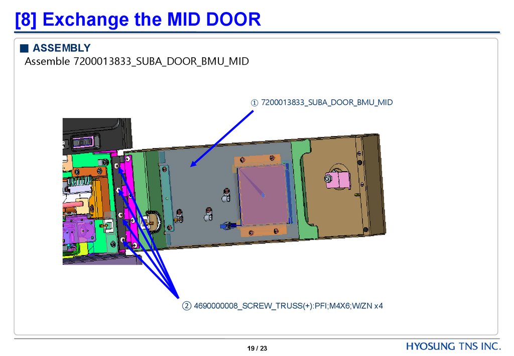
[8] Exchange the MID DOOR■ ASSEMBLY
Assemble 7200013833_SUBA_DOOR_BMU_MID
① 7200013833_SUBA_DOOR_BMU_MID
② 4690000008_SCREW_TRUSS(+):PFI;M4X6;W/ZN x4
19 / 23
20.
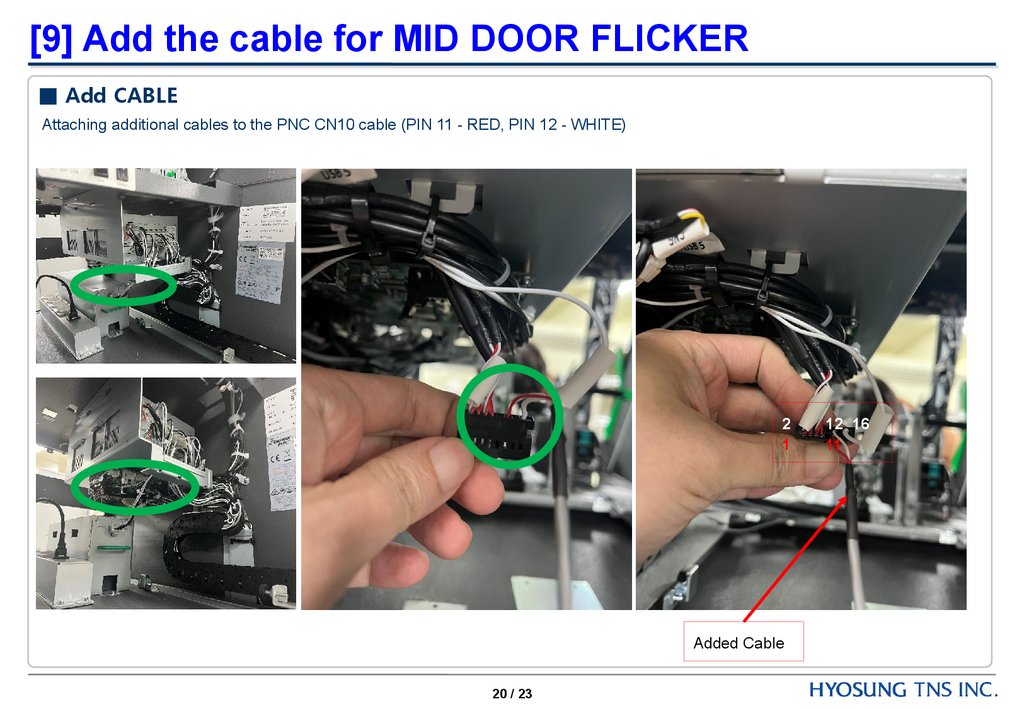
[9] Add the cable for MID DOOR FLICKER■ Add CABLE
Attaching additional cables to the PNC CN10 cable (PIN 11 - RED, PIN 12 - WHITE)
2
1
Added Cable
20 / 23
12 16
11
21.
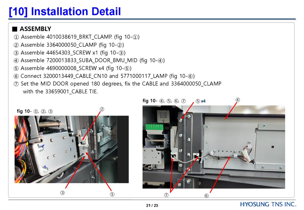
[10] Installation Detail■ ASSEMBLY
① Assemble 4010038619_BRKT_CLAMP. (fig 10-①)
② Assemble 3364000050_CLAMP (fig 10-②)
③ Assemble 44654303_SCREW x1 (fig 10-③)
④ Assemble 7200013833_SUBA_DOOR_BMU_MID (fig 10-④)
⑤ Assemble 4690000008_SCREW x4 (fig 10-⑤)
⑥ Connect 3200013449_CABLE_CN10 and 5771000117_LAMP (fig 10-⑥)
⑦ Set the MID DOOR opened 180 degrees, fix the CABLE and 3364000050_CLAMP
with the 33659001_CABLE TIE.
fig 10- ④, ⑤, ⑥, ⑦
⑤ x4
②
fig 10- ①, ②, ③
③
①
⑦
21 / 23
⑥
④
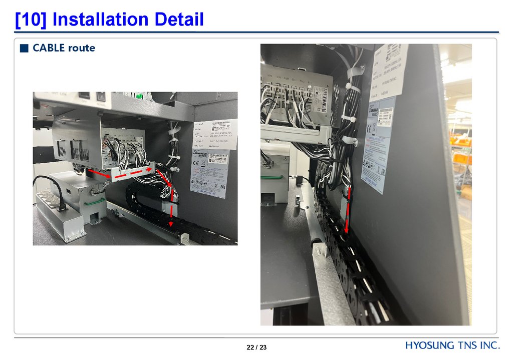
22.
[10] Installation Detail■ CABLE route
22 / 23
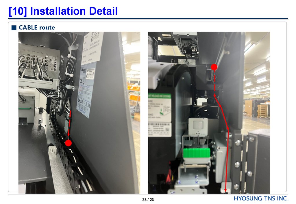
23.
[10] Installation Detail■ CABLE route
23 / 23
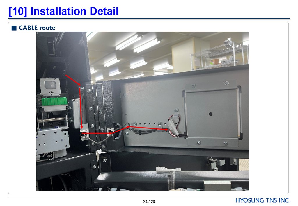
24.
[10] Installation Detail■ CABLE route
24 / 23