Similar presentations:
")


4-4) Maintenance (iPECS-MG)
1.
MaintenanceBusiness Enabled Communications
2.
Contents• System Maintenance by Web-Admin
• Text Database Management
• Trace & Maintenance
• System Recovery
3.
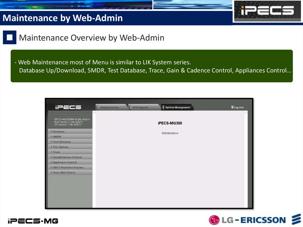
Maintenance by Web-AdminMaintenance Overview by Web-Admin
- Web Maintenance most of Menu is similar to LIK System series.
Database Up/Download, SMDR, Test Database, Trace, Gain & Cadence Control, Appliances Control… etc
4.
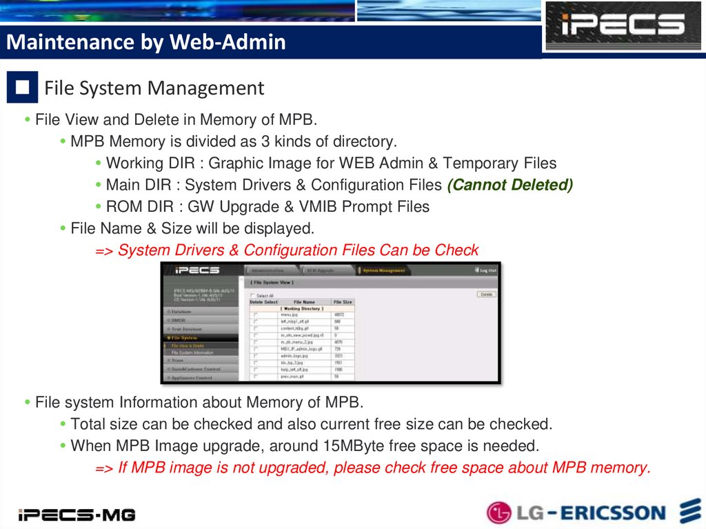
Maintenance by Web-AdminFile System Management
File View and Delete in Memory of MPB.
MPB Memory is divided as 3 kinds of directory.
Working DIR : Graphic Image for WEB Admin & Temporary Files
Main DIR : System Drivers & Configuration Files (Cannot Deleted)
ROM DIR : GW Upgrade & VMIB Prompt Files
File Name & Size will be displayed.
=> System Drivers & Configuration Files Can be Check
File system Information about Memory of MPB.
Total size can be checked and also current free size can be checked.
When MPB Image upgrade, around 15MByte free space is needed.
=> If MPB image is not upgraded, please check free space about MPB memory.
5.
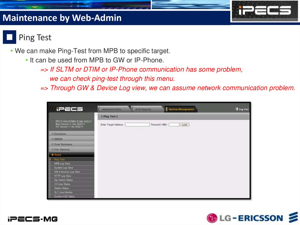
Maintenance by Web-AdminPing Test
We can make Ping-Test from MPB to specific target.
It can be used from MPB to GW or IP-Phone.
=> If SLTM or DTIM or IP-Phone communication has some problem,
we can check ping-test through this menu.
=> Through GW & Device Log view, we can assume network communication problem.
6.
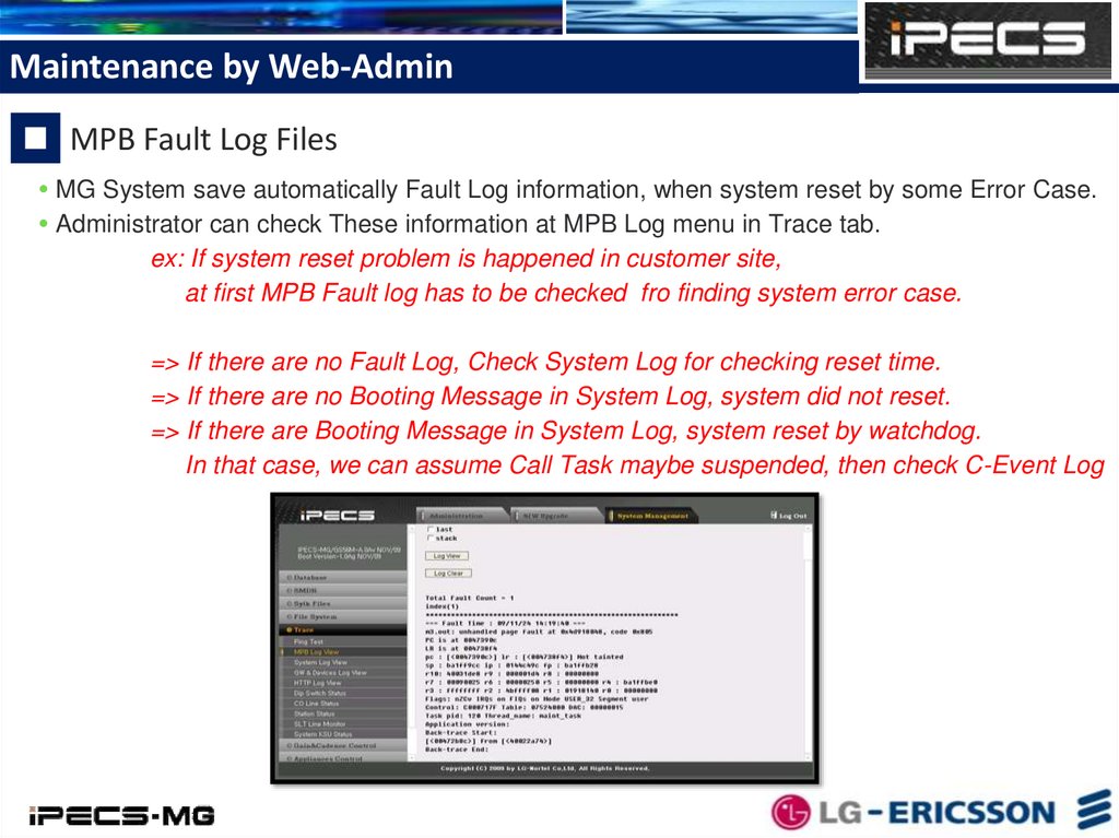
Maintenance by Web-AdminMPB Fault Log Files
MG System save automatically Fault Log information, when system reset by some Error Case.
Administrator can check These information at MPB Log menu in Trace tab.
ex: If system reset problem is happened in customer site,
at first MPB Fault log has to be checked fro finding system error case.
=> If there are no Fault Log, Check System Log for checking reset time.
=> If there are no Booting Message in System Log, system did not reset.
=> If there are Booting Message in System Log, system reset by watchdog.
In that case, we can assume Call Task maybe suspended, then check C-Event Log
7.
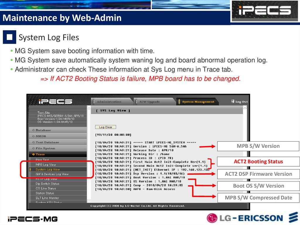
Maintenance by Web-AdminSystem Log Files
MG System save booting information with time.
MG System save automatically system waning log and board abnormal operation log.
Administrator can check These information at Sys Log menu in Trace tab.
=> If ACT2 Booting Status is failure, MPB board has to be changed.
MPB S/W Version
ACT2 Booting Status
ACT2 DSP Firmware Version
Boot OS S/W Version
MPB S/W Compressed Date
8.
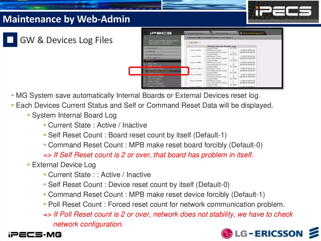
Maintenance by Web-AdminGW & Devices Log Files
MG System save automatically Internal Boards or External Devices reset log.
Each Devices Current Status and Self or Command Reset Data will be displayed.
System Internal Board Log
Current State : Active / Inactive
Self Reset Count : Board reset count by itself (Default-1)
Command Reset Count : MPB make reset board forcibly (Default-0)
=> If Self Reset count is 2 or over, that board has problem in itself.
External Device Log
Current State : : Active / Inactive
Self Reset Count : Device reset count by itself (Default-0)
Command Reset Count : MPB make reset device forcibly (Default-1)
Poll Reset Count : Forced reset count for network communication problem.
=> If Poll Reset count is 2 or over, network does not stability, we have to check
network configuration.
9.
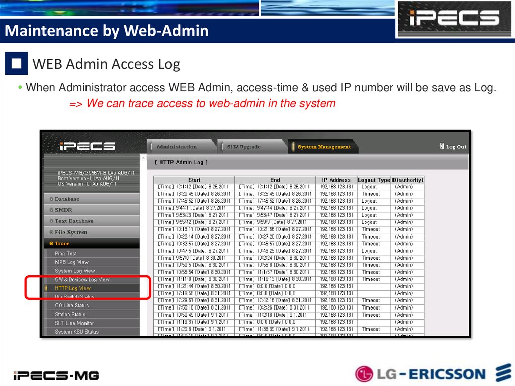
Maintenance by Web-AdminWEB Admin Access Log
When Administrator access WEB Admin, access-time & used IP number will be save as Log.
=> We can trace access to web-admin in the system
10.
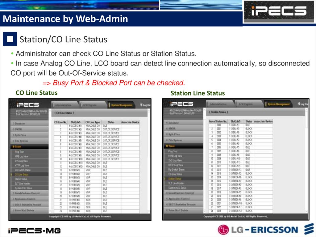
Maintenance by Web-AdminStation/CO Line Status
Administrator can check CO Line Status or Station Status.
In case Analog CO Line, LCO board can detect line connection automatically, so disconnected
CO port will be Out-Of-Service status.
=> Busy Port & Blocked Port can be checked.
CO Line Status
Station Line Status
11.
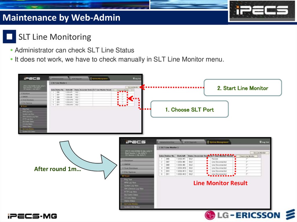
Maintenance by Web-AdminSLT Line Monitoring
Administrator can check SLT Line Status
It does not work, we have to check manually in SLT Line Monitor menu.
2. Start Line Monitor
1. Choose SLT Port
After round 1m…
Line Monitor Result
12.
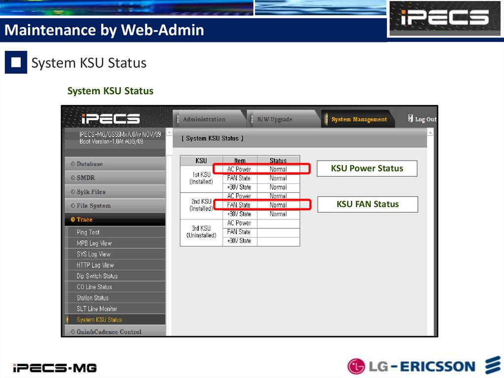
Maintenance by Web-AdminSystem KSU Status
System KSU Status
KSU Power Status
KSU FAN Status
13.
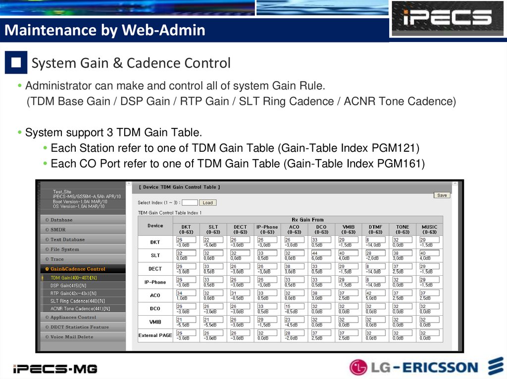
Maintenance by Web-AdminSystem Gain & Cadence Control
Administrator can make and control all of system Gain Rule.
(TDM Base Gain / DSP Gain / RTP Gain / SLT Ring Cadence / ACNR Tone Cadence)
System support 3 TDM Gain Table.
Each Station refer to one of TDM Gain Table (Gain-Table Index PGM121)
Each CO Port refer to one of TDM Gain Table (Gain-Table Index PGM161)
14.
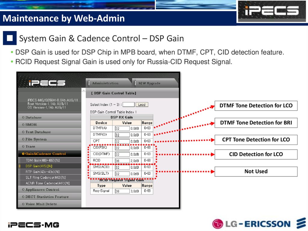
Maintenance by Web-AdminSystem Gain & Cadence Control – DSP Gain
DSP Gain is used for DSP Chip in MPB board, when DTMF, CPT, CID detection feature.
RCID Request Signal Gain is used only for Russia-CID Request Signal.
DTMF Tone Detection for LCO
DTMF Tone Detection for BRI
CPT Tone Detection for LCO
CID Detection for LCO
Not Used
15.
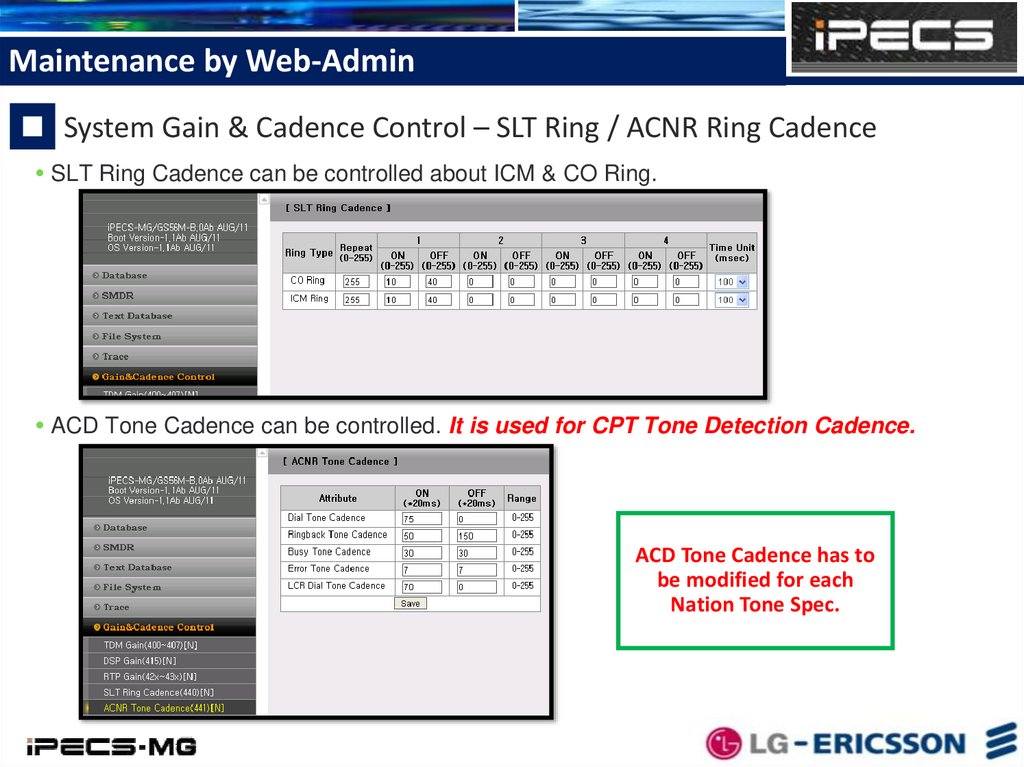
Maintenance by Web-AdminSystem Gain & Cadence Control – SLT Ring / ACNR Ring Cadence
SLT Ring Cadence can be controlled about ICM & CO Ring.
ACD Tone Cadence can be controlled. It is used for CPT Tone Detection Cadence.
ACD Tone Cadence has to
be modified for each
Nation Tone Spec.
16.
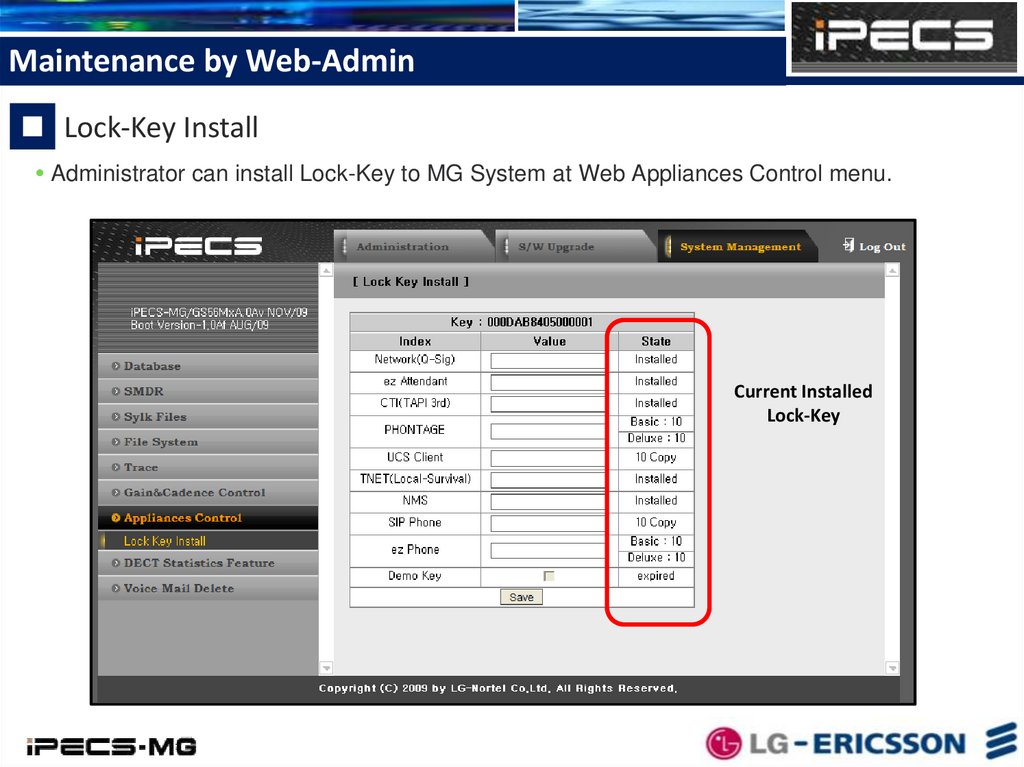
Maintenance by Web-AdminLock-Key Install
Administrator can install Lock-Key to MG System at Web Appliances Control menu.
Current Installed
Lock-Key
17.
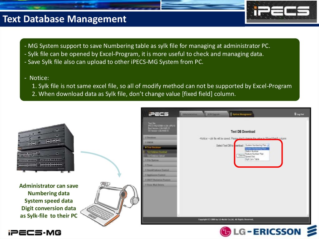
Text Database Management- MG System support to save Numbering table as sylk file for managing at administrator PC.
- Sylk file can be opened by Excel-Program, it is more useful to check and managing data.
- Save Sylk file also can upload to other iPECS-MG System from PC.
- Notice:
1. Sylk file is not same excel file, so all of modify method can not be supported by Excel-Program
2. When download data as Sylk file, don’t change value [fixed field] column.
Administrator can save
Numbering data
System speed data
Digit conversion data
as Sylk-file to their PC
18.
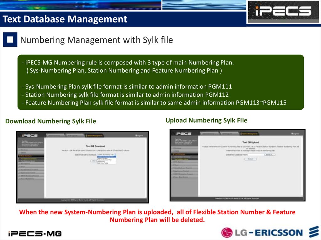
Text Database ManagementNumbering Management with Sylk file
- iPECS-MG Numbering rule is composed with 3 type of main Numbering Plan.
( Sys-Numbering Plan, Station Numbering and Feature Numbering Plan )
- Sys-Numbering Plan sylk file format is similar to admin information PGM111
- Station Numbering sylk file format is similar to admin information PGM112
- Feature Numbering Plan sylk file format is similar to same admin information PGM113~PGM115
Download Numbering Sylk File
Upload Numbering Sylk File
When the new System-Numbering Plan is uploaded, all of Flexible Station Number & Feature
Numbering Plan will be deleted.
19.
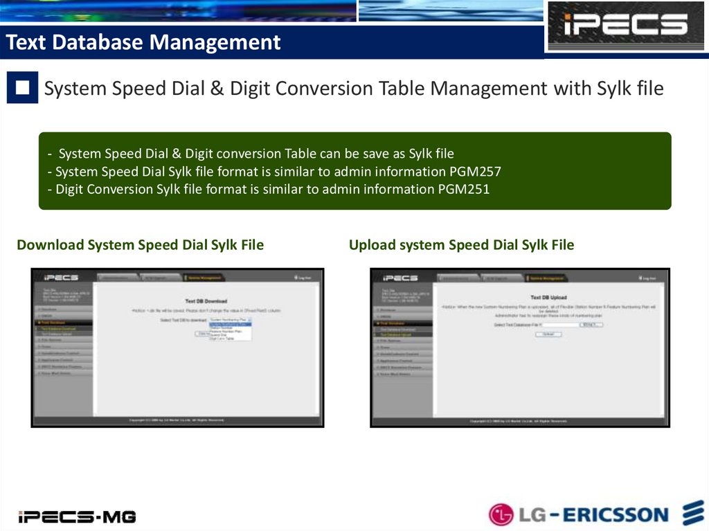
Text Database ManagementSystem Speed Dial & Digit Conversion Table Management with Sylk file
- System Speed Dial & Digit conversion Table can be save as Sylk file
- System Speed Dial Sylk file format is similar to admin information PGM257
- Digit Conversion Sylk file format is similar to admin information PGM251
Download System Speed Dial Sylk File
Upload system Speed Dial Sylk File
20.
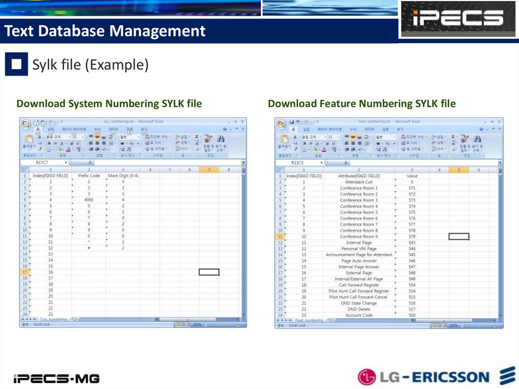
Text Database ManagementSylk file (Example)
Download System Numbering SYLK file
Download Feature Numbering SYLK file
21.
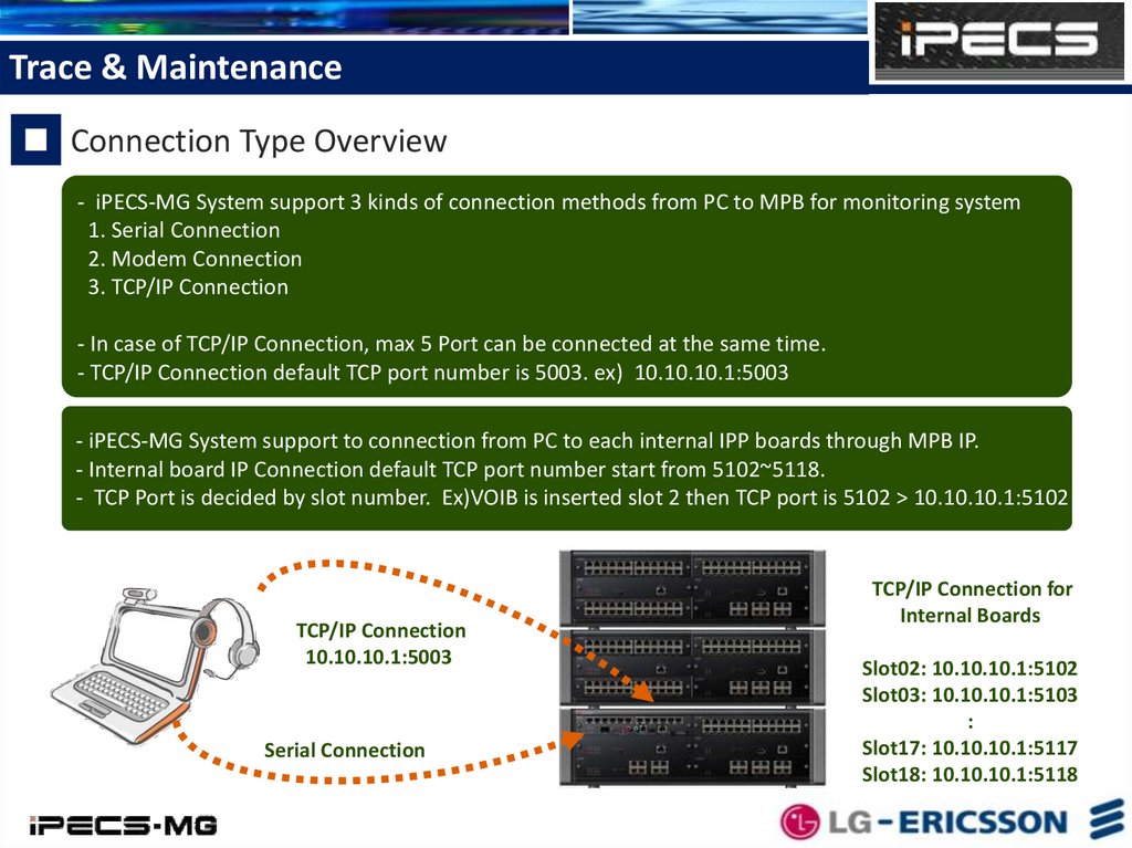
Trace & MaintenanceConnection Type Overview
- iPECS-MG System support 3 kinds of connection methods from PC to MPB for monitoring system
1. Serial Connection
2. Modem Connection
3. TCP/IP Connection
- In case of TCP/IP Connection, max 5 Port can be connected at the same time.
- TCP/IP Connection default TCP port number is 5003. ex) 10.10.10.1:5003
- iPECS-MG System support to connection from PC to each internal IPP boards through MPB IP.
- Internal board IP Connection default TCP port number start from 5102~5118.
- TCP Port is decided by slot number. Ex)VOIB is inserted slot 2 then TCP port is 5102 > 10.10.10.1:5102
TCP/IP Connection
10.10.10.1:5003
Serial Connection
TCP/IP Connection for
Internal Boards
Slot02: 10.10.10.1:5102
Slot03: 10.10.10.1:5103
:
Slot17: 10.10.10.1:5117
Slot18: 10.10.10.1:5118
22.
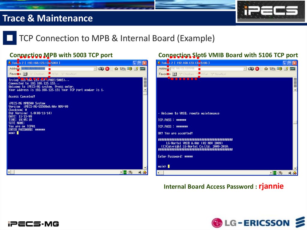
Trace & MaintenanceTCP Connection to MPB & Internal Board (Example)
Connection MPB with 5003 TCP port
Connection Slot6 VMIB Board with 5106 TCP port
Internal Board Access Password : rjannie
23.
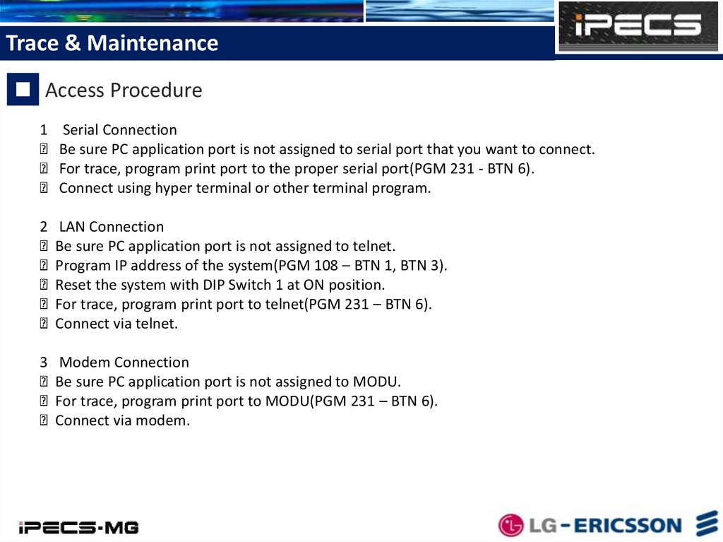
Trace & MaintenanceAccess Procedure
1 Serial Connection
Be sure PC application port is not assigned to serial port that you want to connect.
For trace, program print port to the proper serial port(PGM 231 - BTN 6).
Connect using hyper terminal or other terminal program.
2 LAN Connection
Be sure PC application port is not assigned to telnet.
Program IP address of the system(PGM 108 – BTN 1, BTN 3).
Reset the system with DIP Switch 1 at ON position.
For trace, program print port to telnet(PGM 231 – BTN 6).
Connect via telnet.
3 Modem Connection
Be sure PC application port is not assigned to MODU.
For trace, program print port to MODU(PGM 231 – BTN 6).
Connect via modem.
24.
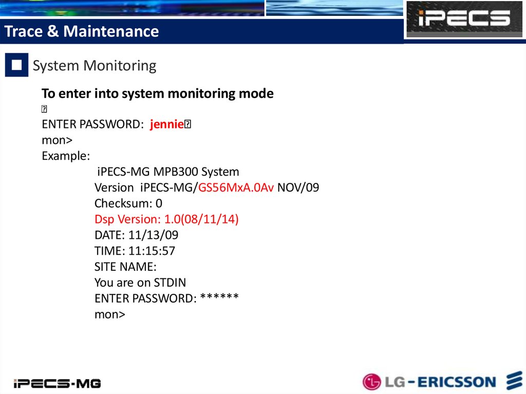
Trace & MaintenanceSystem Monitoring
To enter into system monitoring mode
ENTER PASSWORD: jennie
mon>
Example:
iPECS-MG MPB300 System
Version iPECS-MG/GS56MxA.0Av NOV/09
Checksum: 0
Dsp Version: 1.0(08/11/14)
DATE: 11/13/09
TIME: 11:15:57
SITE NAME:
You are on STDIN
ENTER PASSWORD: ******
mon>
25.
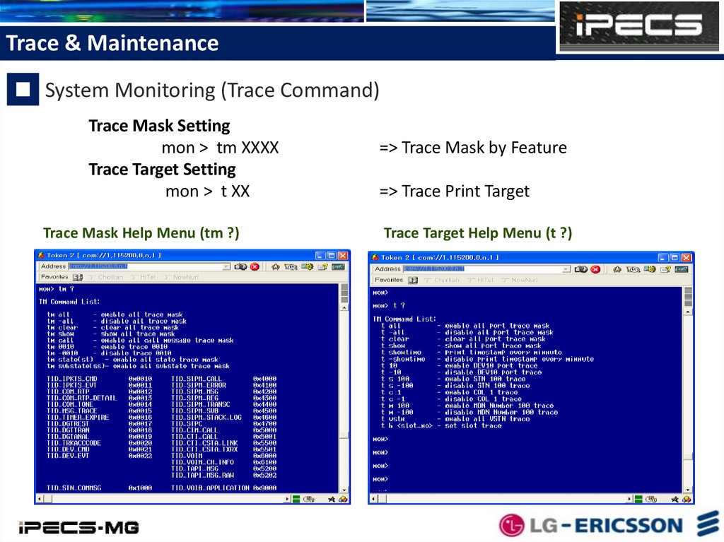
Trace & MaintenanceSystem Monitoring (Trace Command)
Trace Mask Setting
mon > tm XXXX
Trace Target Setting
mon > t XX
Trace Mask Help Menu (tm ?)
=> Trace Mask by Feature
=> Trace Print Target
Trace Target Help Menu (t ?)
26.
Trace & MaintenanceSystem Monitoring (Trace Command)
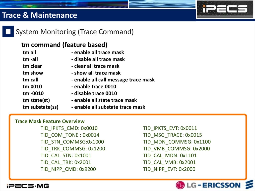
tm command (feature based)
tm all
tm -all
tm clear
tm show
tm call
tm 0010
tm -0010
tm state(st)
tm substate(ss)
- enable all trace mask
- disable all trace mask
- clear all trace mask
- show all trace mask
- enable all call message trace mask
- enable trace 0010
- disable trace 0010
- enable all state trace mask
- enable all substate trace mask
Trace Mask Feature Overview
TID_IPKTS_CMD: 0x0010
TID_COM_TONE : 0x0014
TID_STN_COMMSG:0x1000
TID_TRK_COMMSG: 0x1200
TID_CAL_STN: 0x1001
TID_CAL_TRK: 0x2001
TID_NIPP_CMD: 0x9200
TID_IPKTS_EVT: 0x0011
TID_MSG_TRACE: 0x0015
TID_MDN_COMMSG: 0x1100
TID_VMB_COMMSG: 0x2000
TID_CAL_MDN: 0x1101
TID_CAL_VMB: 0x2001
TID_NIPP_EVT: 0x2000
27.
Trace & MaintenanceSystem Monitoring (Trace Command)
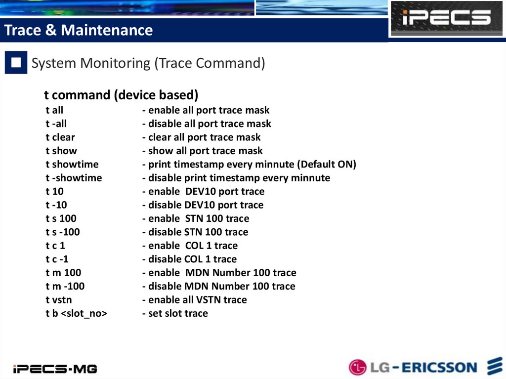
t command (device based)
t all
t -all
t clear
t show
t showtime
t -showtime
t 10
t -10
t s 100
t s -100
tc1
t c -1
t m 100
t m -100
t vstn
t b <slot_no>
- enable all port trace mask
- disable all port trace mask
- clear all port trace mask
- show all port trace mask
- print timestamp every minnute (Default ON)
- disable print timestamp every minnute
- enable DEV10 port trace
- disable DEV10 port trace
- enable STN 100 trace
- disable STN 100 trace
- enable COL 1 trace
- disable COL 1 trace
- enable MDN Number 100 trace
- disable MDN Number 100 trace
- enable all VSTN trace
- set slot trace
28.
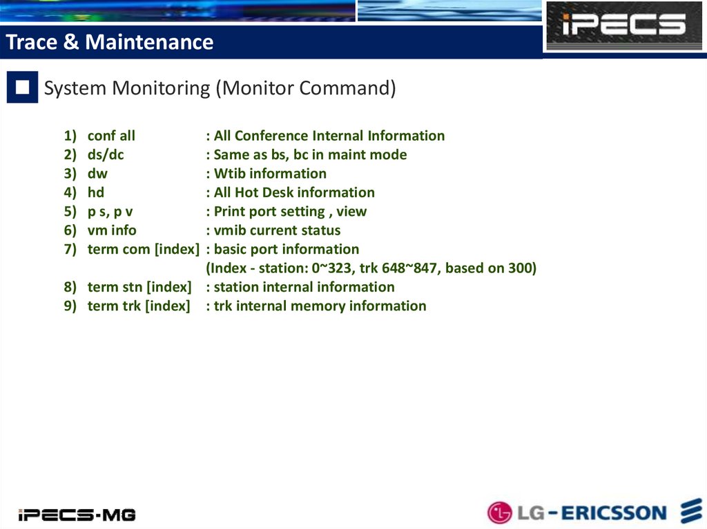
Trace & MaintenanceSystem Monitoring (Monitor Command)
1) conf all
: All Conference Internal Information
2) ds/dc
: Same as bs, bc in maint mode
3) dw
: Wtib information
4) hd
: All Hot Desk information
5) p s, p v
: Print port setting , view
6) vm info
: vmib current status
7) term com [index] : basic port information
(Index - station: 0~323, trk 648~847, based on 300)
8) term stn [index] : station internal information
9) term trk [index] : trk internal memory information
29.
Trace & MaintenanceSystem Maintenance
To enter into system monitoring mode
ENTER PASSWORD: brandy
maint>
30.
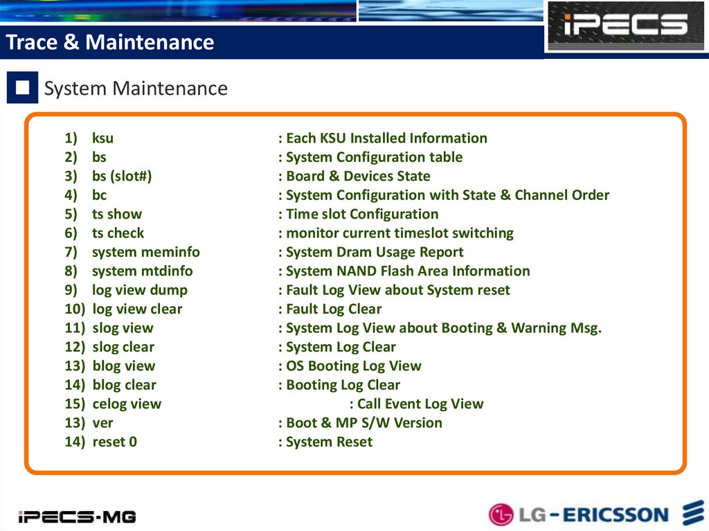
Trace & MaintenanceSystem Maintenance
1) ksu
2) bs
3) bs (slot#)
4) bc
5) ts show
6) ts check
7) system meminfo
8) system mtdinfo
9) log view dump
10) log view clear
11) slog view
12) slog clear
13) blog view
14) blog clear
15) celog view
13) ver
14) reset 0
: Each KSU Installed Information
: System Configuration table
: Board & Devices State
: System Configuration with State & Channel Order
: Time slot Configuration
: monitor current timeslot switching
: System Dram Usage Report
: System NAND Flash Area Information
: Fault Log View about System reset
: Fault Log Clear
: System Log View about Booting & Warning Msg.
: System Log Clear
: OS Booting Log View
: Booting Log Clear
: Call Event Log View
: Boot & MP S/W Version
: System Reset
31.
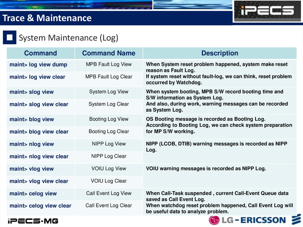
Trace & MaintenanceSystem Maintenance (Log)
Command
Command Name
Description
maint> log view dump
MPB Fault Log View
maint> log view clear
MPB Fault Log Clear
When System reset problem happened, system make reset
reason as Fault Log.
If system reset without fault-log, we can think, reset problem
occurred by Watchdog.
maint> slog view
System Log View
maint> slog view clear
System Log Clear
maint> blog view
Booting Log View
maint> blog view clear
Booting Log Clear
maint> nlog view
NIPP Log View
maint> nlog view clear
NIPP Log Clear
maint> vlog view
VOIU Log View
maint> vlog view clear
VOIU Log Clear
maint> celog view
Call Event Log View
maint> celog view clear
Call Event Log Clear
When system booting, MPB S/W record booting time and
S/W information as System Log.
And also, during work, warning messages can be recorded
as System Log.
OS Booting message is recorded as Booting Log.
According to Booting Log, we can check system preparation
for MP S/W working.
NIPP (LCOB, DTIB) warning messages is recorded as NIPP
Log.
VOIU warning messages is recorded as NIPP Log.
When Call-Task suspended , current Call-Event Queue data
saved as Call Event Log.
When watchdog reset problem happened, Call Event Log will
be useful data to analyze problem.
32.
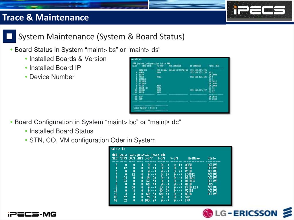
Trace & MaintenanceSystem Maintenance (System & Board Status)
Board Status in System “maint> bs” or “maint> ds”
Installed Boards & Version
Installed Board IP
Device Number
Board Configuration in System “maint> bc” or “maint> dc”
Installed Board Status
STN, CO, VM configuration Oder in System
33.
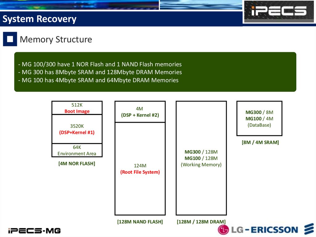
System RecoveryMemory Structure
- MG 100/300 have 1 NOR Flash and 1 NAND Flash memories
- MG 300 has 8Mbyte SRAM and 128Mbyte DRAM Memories
- MG 100 has 4Mbyte SRAM and 64Mbyte DRAM Memories
512K
Boot Image
4M
(DSP + Kernel #2)
MG300 / 8M
MG100 / 4M
(DataBase)
3520K
(DSP+Kernel #1)
[8M / 4M SRAM]
64K
Environment Area
[4M NOR FLASH]
124M
(Root File System)
[128M NAND FLASH]
MG300 / 128M
MG100 / 128M
(Working Memory)
[128M / 128M DRAM]
34.
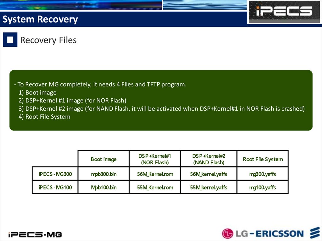
System RecoveryRecovery Files
- To Recover MG completely, it needs 4 Files and TFTP program.
1) Boot image
2) DSP+Kernel #1 image (for NOR Flash)
3) DSP+Kernel #2 image (for NAND Flash, it will be activated when DSP+Kernel#1 in NOR Flash is crashed)
4) Root File System
Boot image
DSP+Kernel#1
(NOR Flash)
DSP+Kernel#2
(NAND Flash)
Root File System
iPECS-MG300
mpb300.bin
56M_Kernel.rom
56M_kernel.yaffs
mg300.yaffs
iPECS-MG100
Mpb100.bin
55M_Kernel.rom
55M_kernel.yaffs
mg100.yaffs
35.
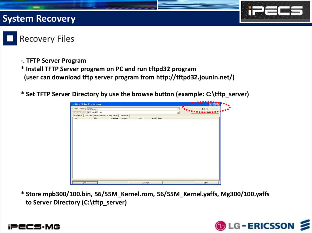
System RecoveryRecovery Files
-. TFTP Server Program
* Install TFTP Server program on PC and run tftpd32 program
(user can download tftp server program from http://tftpd32.jounin.net/)
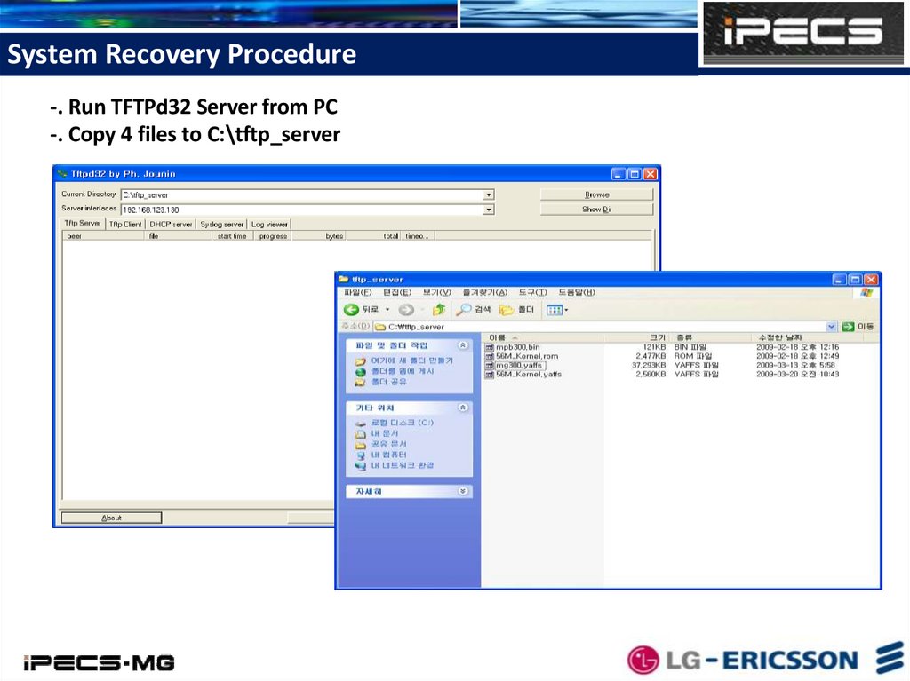
* Set TFTP Server Directory by use the browse button (example: C:\tftp_server)
* Store mpb300/100.bin, 56/55M_Kernel.rom, 56/55M_Kernel.yaffs, Mg300/100.yaffs
to Server Directory (C:\tftp_server)
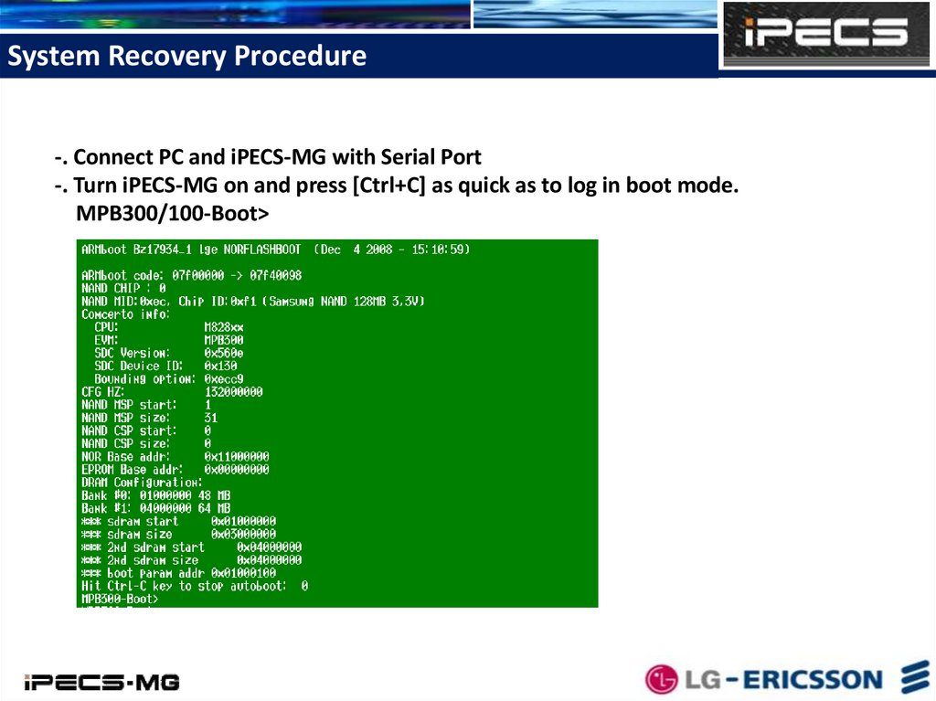
36.
System Recovery Procedure-. Connect PC and iPECS-MG with Serial Port
-. Turn iPECS-MG on and press [Ctrl+C] as quick as to log in boot mode.
MPB300/100-Boot>
37.
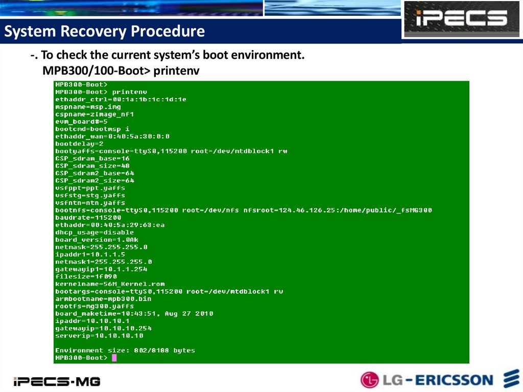
System Recovery Procedure-. To check the current system’s boot environment.
MPB300/100-Boot> printenv
38.
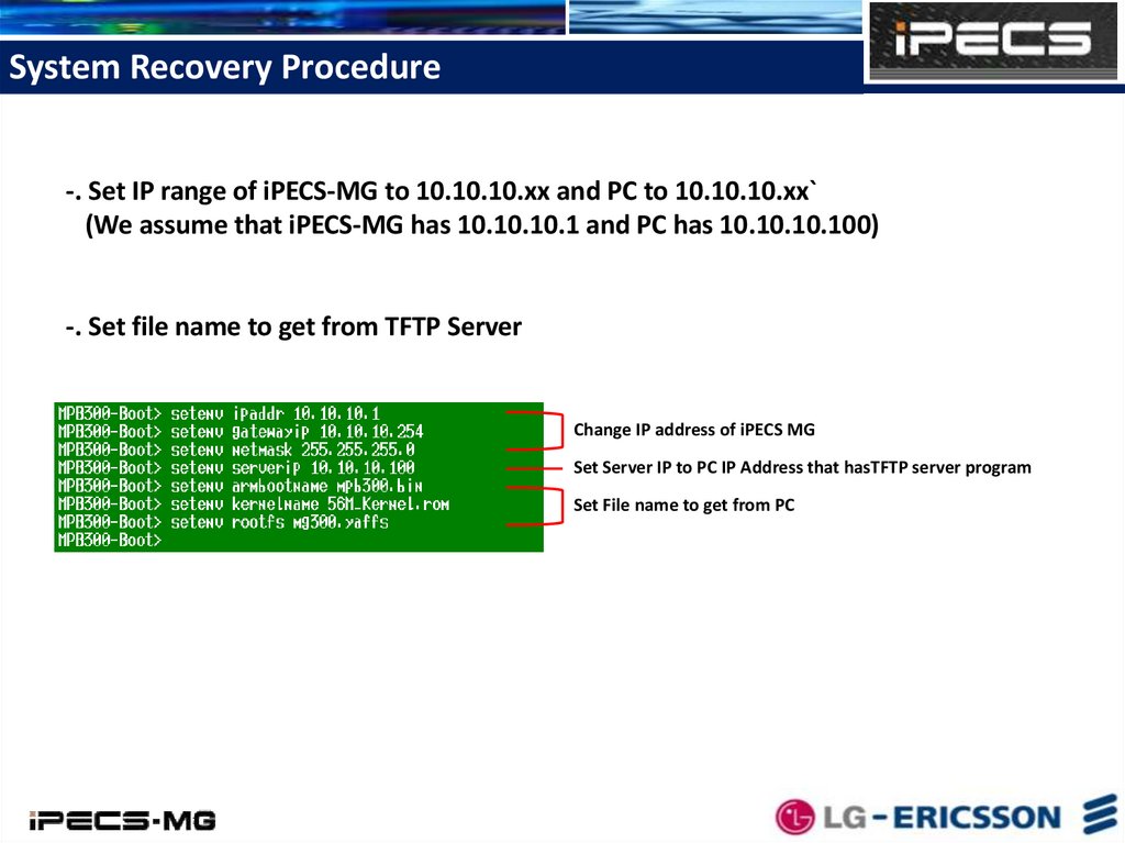
System Recovery Procedure-. Set IP range of iPECS-MG to 10.10.10.xx and PC to 10.10.10.xx`
(We assume that iPECS-MG has 10.10.10.1 and PC has 10.10.10.100)
-. Set file name to get from TFTP Server
Change IP address of iPECS MG
Set Server IP to PC IP Address that hasTFTP server program
Set File name to get from PC
39.
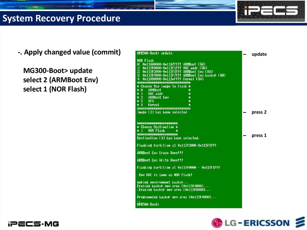
System Recovery Procedure-. Apply changed value (commit)
update
MG300-Boot> update
select 2 (ARMBoot Env)
select 1 (NOR Flash)
press 2
press 1
40.
System Recovery Procedure-. Run TFTPd32 Server from PC
-. Copy 4 files to C:\tftp_server
41.
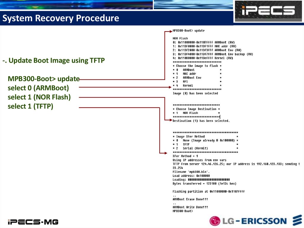
System Recovery Procedure-. Update Boot Image using TFTP
MPB300-Boot> update
select 0 (ARMBoot)
select 1 (NOR Flash)
select 1 (TFTP)
42.
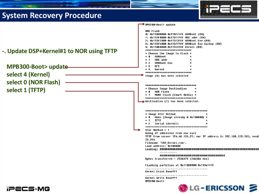
System Recovery Procedure-. Update DSP+Kernel#1 to NOR using TFTP
MPB300-Boot> update
select 4 (Kernel)
select 0 (NOR Flash)
select 1 (TFTP)
43.
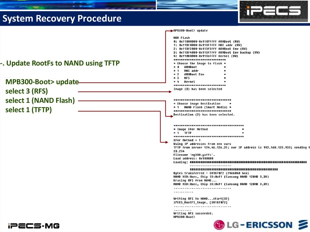
System Recovery Procedure-. Update RootFs to NAND using TFTP
MPB300-Boot> update
select 3 (RFS)
select 1 (NAND Flash)
select 1 (TFTP)
44.
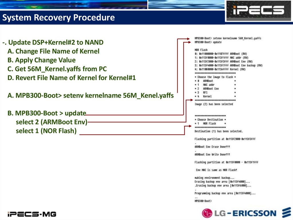
System Recovery Procedure-. Update DSP+Kernel#2 to NAND
A. Change File Name of Kernel
B. Apply Change Value
C. Get 56M_Kernel.yaffs from PC
D. Revert File Name of Kernel for Kernel#1
A. MPB300-Boot> setenv kernelname 56M_Kenel.yaffs
B. MPB300-Boot > update
select 2 (ARMBoot Env)
select 1 (NOR Flash)
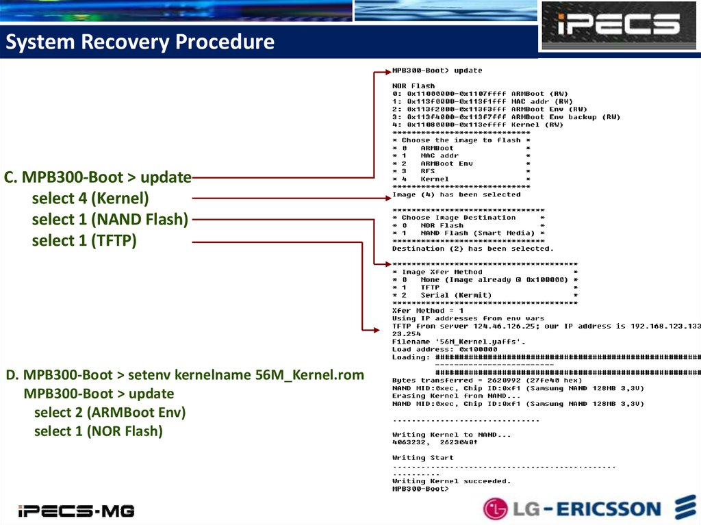
45.
System Recovery ProcedureC. MPB300-Boot > update
select 4 (Kernel)
select 1 (NAND Flash)
select 1 (TFTP)
D. MPB300-Boot > setenv kernelname 56M_Kernel.rom
MPB300-Boot > update
select 2 (ARMBoot Env)
select 1 (NOR Flash)
46.
System Recovery Procedure-. Reset iPECS-MG System after updating 4 files.