 industry
Similar presentations:


United States Patent
1.
OUnited States Patent
72 inventor Wilhelm Buechler
Munich, Germany
21 Appl. No. 771,553
22 Filed
Oct. 29, 1968
45 Patented Mar. 23, 1971
73 Assignee Peters
Widmann
gesellschaft
Munich, Germany
32 Priority
(33)
Oct. 30, 1967
Germany
31
P 16 S8 587.8
54). APPARATUSFOR CONCRETING MULTIPLE
SECTIONSTRUCTURES, PARTICULARLY
BRIDGESUPPORTSOFREINFORCEDOR
PRESTRESSED CONCRETE
9 Claims, 11 Drawing Figs.
52) U.S.C. .......................................................
14/1,
25/13.6,264/33
51) int.C......................................................... E01d 1100
(50 Field of Search............................................ 25/131X;
264/33, 34; 1471; 52/122-127, 173,632
56
References Cited
UNITED STATES PATENTS
1,584,756 5/1926 Dougherty.................... 25/131.6UX
(ii) 3,571,835
1,70l., 13 2/929 Keller........................... 25/13. UX
2,060,046 l/1936 Giacomo..................... 25/3.5UX
2,578,057 12/195. Flores...........................
3,003,219 10/1961 Suter.........
O
3,299,9l 1967 Mantscheff..................
25/35
264/33
141X
Primary Examiner-Jacob L. Nackenoff
att
Robert H. Jacob
orney-Kobert
H. Jaco
ABSTRACT: Apparatus for concreting multiple section or
multipanel structures such as elevated highway and bridge
structures of reinforced or prestressed concrete, comprising
two girders that are movable relative to one another, one of
which is a scaffold girder and the other an advancing girder
that supports the scaffold girder as it is advanced, which gir
ders are generally of the same length and disposed across a
section being concretcd where they absorb the load together,
and which after hardening of the concrete can be shifted to a
new section to be concreted, with the advancing girder mov
ing across the new section first while supported on the scaffold
girder, whereupon the scaffold girder is moved into position
above the advancing girder with its front end supported
thereon and the rearward end supported on a frame having
rollers.
2.
PATENTED AR 23973,571,835
SHEET i OF 4
S
n
S on
S.
S
O'K
Z
CO
|
&
Q.N.
s
S.
INVENTOR,
AWZAZM7 asøgaae
" a ty.
3.
PATENTED MAR 23973,571,835
SHEET 2 OF 4
INVENTOR,
WA/AZM adoA4%?
BY eary
4.
PATENTED AR 23973,571,835
SHEET 3 OF 4.
-
11
37
36 NS-3,4
Y2A%22
22%
2322f4
2222222222
assig-E
6.
SS
R
2
Sy"WS
11
zza
NSTN
Z%224%.72272
Ves
INVENTOR.
WZAZMy asocazae
BY /624/1
5.
PATENTED MAR 23973,571,835
- 26
l
zz-z-z%
2. 74
/
31
14
5-N
N
tis
Zoo
Z.
-
XXX.AXY
1.
starsays:
N
27
ZaayaaaaaaaaaaaaaaaZZYZZZZYaaZZYYYYaa2a2a2.
---
-- - -
aduated
- --- - -
-
R.C.R.A. tal
INVENTOR.
A/Z/7ZZM4OCAA
" a 44
6.
3,571,8352
The basic concept of the apparatus in accordance with the
STRUCTURES, PARTICULARLY BRIDGESUPPORTS OF
invention is considered to be that for pure displacement
REINFORCED OR PRESTRESSED CONCRETE
problems, for which as a consequence of the absence of struc
tural
loads a smaller carrying capacity may be tolerated, they
BACKGROUND OF THE INVENTION
can each be shifted one relative to the other, while during
The present invention relates to equipment or apparatus for concreting, i.e., at a time when no shifting movement occurs
concreting multiple section elevated structures, particularly but when big loads must be absorbed, both girders are
elevated highways and bridges. More in particular, the inven disposed in the same bridge section and take part in absorbing
tion is concerned with equipment and apparatus for construct the structural loads.
ing bridge supporting structures of reinforced or prestressed 10 Owing to its particular manner of construction the equip
concrete. The equipment comprises two girders that are dis ment in accordance with the invention provides the further
placeable or slidable relative to one another, one of which is in advantage that due to the shorter length of the advancing
the form of a scaffold or casing girder and the other as an ad girder as compared to that of the known arrangement, the
vancing girder for supporting the former while it is advanced 5 same can be swung more readily in horizontal directions, so
as the construction progresses.
that also the construction of curved orangularly offset bridges
An arrangement for concreting elongated structural com is facilitated.
ponents is known from U.S. Pat. No. 3,003,219 which has at
For supporting the scaffold girder on the advancing girder
least one travelling or advancing girder that can be displaced for construction operations, a plurality of equally spaced
longitudinally of the structure in freely cantilevering fashion, 20 hydraulic presses are suitably distributed along the longitu
as well as one or more scaffold girders which can be con dinal extent of the girder.
nected with the scaffold girder. In this arrangement the
The travelling br advancing girder itself is arranged to ride
travelling or advancing girder is provided above the roadway in a suspended frame that is firmly mounted to the forward
or surface of the bridge and arranged in a manner that with end of the scaffold girder while it is supported at its rearward
one part, which cantilevers out over the part of the structure 25 end against the bottom of the scaffold girder by way of inter
which has already been concreted, it can hold the one end of
rollers. The hanging frame may only have two ledges
the scaffolding girders that are held at both ends and disposed mediate
in
lieu
of
lower connecting bar, which are rigidly connected
below the bridge plate, and that the scaffolding girders are dis with the alateral
or vertical bars, which ledges are provided
placeable on the advancing girder and on the concreted part with
riding rollers for carrying the advancing girder.
of the structure by at least the distance between two columns. 30 The scaffold girder as well as the advancing girder are
The advancing girder in that arrangement serves merely for
in the form of torsion resisting box girders.
shifting the scaffold girder or girders after completion of a suitably
The
scaffold
girder is provided on both sides with freely
bridge section while the supporting rollers of the scaffold cantilevering transverse
beams for mounting the casings for
girder run on the advancing girder. In order to be safely ad the bridge structure which
suspended from the beams.
35
vanced onto the roller block or support that has already been Generally U-shaped frames are
are
provided as casing carriers,
prepared on the next column, the advancing girder must span whose upper horizontal leg is disposed
parallel to one of the
two sections. It serves only for the advancing of the scaffold or transverse beams to which it is connected
a manner to be
casing girder or girders and is idle while the concreting takes adjustable in height, while the verticalin connecting
bar
place.
the connection externally of the roadway panel
The operation of this known arrangement takes place in 40 completes
that after completion of one bridge section the casing girder is with the leg carrying the casing below the panel.
advanced first, while it is suspended at its forward end on the
BRIEF DESCRIPTION OF THEDRAWINGs
advancing girder and at its rearward end on the bridge section
already completed, and that then the advancing roller is ad 45 Further advantages, and features of the invention will
vanced to cantilever out over the length of an entire section to become apparent from the following description of an em
bodiment of the invention illustrated in the accompanying
be supported on the next following column. . . . .
While recognizing the principle of using mutually displacea drawings, in which:
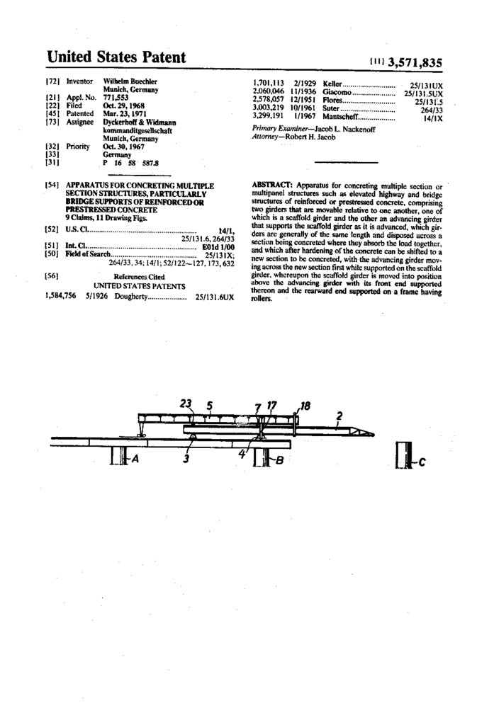
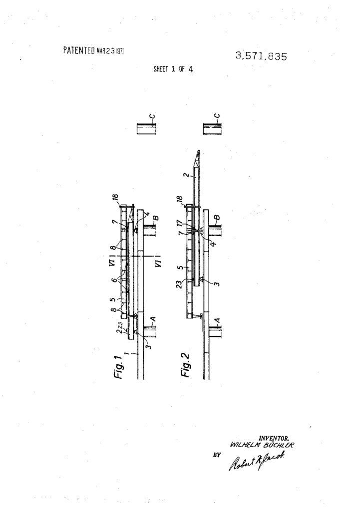
FIGS. 1 to 5 illustrate in schematic side views the construc
ble girders as advantageous for concreting multisection bridge
supporting structures, it is an object of the invention to pro 50 tion of a bridge section in different phases,
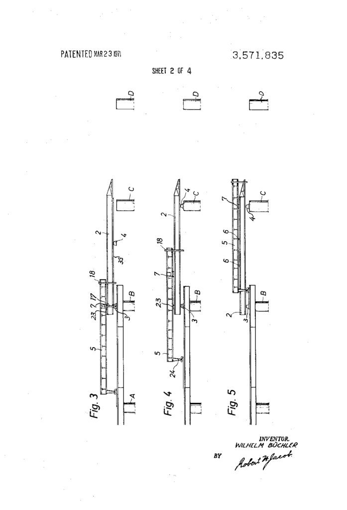
FIG. 6 is a cross section taken along line Vl-VI in FIG. 1,
vide a possibility to decrease the expenses of the apparatus
which can merely be utilized for concreting operations,
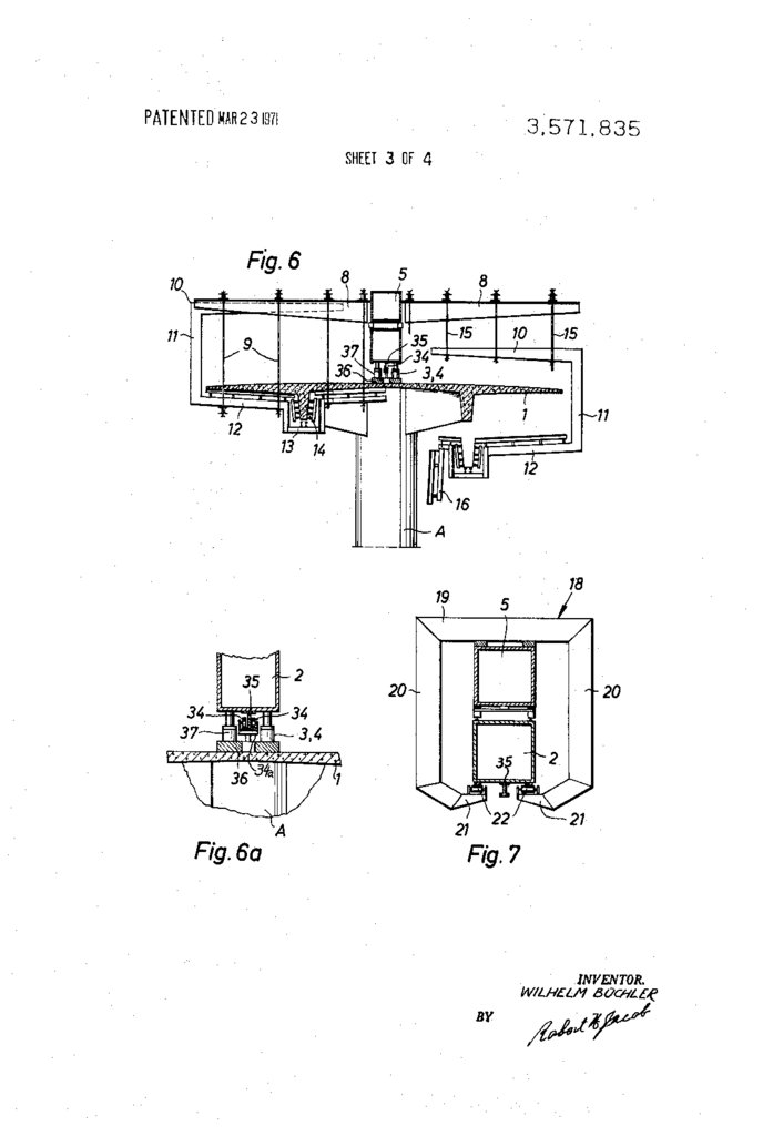
F.G. 6a shows a detail of FIG. 6 to an enlarged scale,
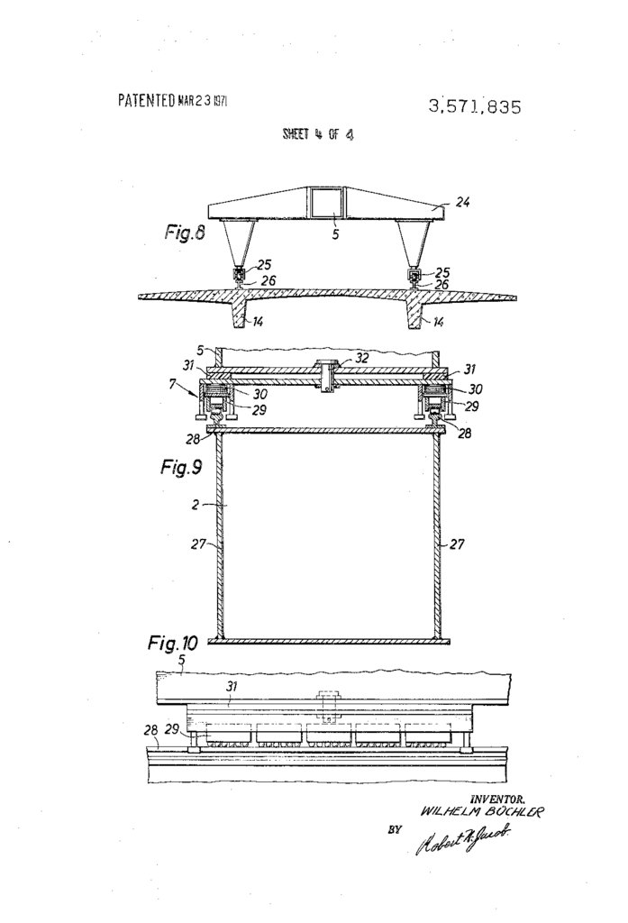
FIG. 7 shows the front support of the advancing girder on
the scaffold girder,
THE INVENTION
FIG. 8 shows the rear travelling mechanism of the scaffold
The problem is solved in accordance with the invention, in
supported on the roadway panel,
that the two girders, the scaffolding girder and the advancing 55 girder
FIG. 9 is a section, and
girder, which during the concreting operation until the
FIG. 10 is a side view of the forward riding mechanism
hardening of the concrete are located in the same bridge sec
tion, are substantially of equal length spanning a bridge sec between the scaffold girder and the advancing girder.
tion and are so constructed and arranged with respect to one 60 DESCRIPTION OF APREFERREDEMBODIMENT
another, that they can be connected with one another in a
FIGS. 1 to 5 illustrate schematically side views of the build
sense of absorbing the structural loads together and that this
connection can be released for the subsequent advancing of ing procedure for a part of a superstructure disposed
the apparatus to the section of the bridge to be produced next.
between the supports or columns A and B of a multiple-sec
For this purpose the scaffold girder is suitably disposed 65 tion bridge structure and the subsequent displacing or sliding
above the advancing girder which is mounted on the bridge of the apparatus in accordance with the invention into the
roadway and supported thereon during the building operation, bridge section disposed between the supports Band C.
while for the displacing or advancing condition the scaffold
In the stage of construction illustrated in FIG. the ap
girder is first firmly supported on the bridge plate or panel, paratus is in that position in which it carries the concrete loads
and the advancing girder is adapted to ride on it, and then the 70 of the bridge section bounded by columns A and B, For this
advancing girder in the new position rests firmly on the bridge the advancing girder 2 located at the botton is supported on
panel at one end and on the next following column at the other the runway of the bridge by two supporting jacks or blocks 3
end, and the scaffold girder can ride with the forward end on and 4 and each, more particularly, in the area of a column A
that girder and with its rearward end on the bridge roadway by or 3. The scaffold girder 5 which is of approximately the same
75 length as the advancing girder 2 is supported by load distribut
means of a support provided with rollers.
APPARATUSFOR CONCRETING MULTIPLESECTION
7.
3,571,8353
ing means in the form of hydraulic presses 6 arranged along its
bottom side, and a carriage means 7 upon the upper surface of
the advancing girder 2, inasmuch as the scaffold girder 5 car
ries the frames or casings with the concrete loads on the trans
verse beams 8, which cantilever laterally outward from the
girder to which they are secured, both girders cooperate at
this stage of construction to absorb the structural loads.
in the cross section through the apparatus in accordance
with the invention reflected by F.G. 6 the left half shows that
4
frame 18 are lowered in order to be free of the advancing
girder, and the rigid connection in the area of the rearward
support 24 of the scaffold girder 5 is removed. The scaffold
girder 5 is then advanced by means of the rollers 25 arranged
at the lower end of the portal shaped support framc 24, which
rollers rest on the rails 26 above the longitudinal girders 4 of
the bridge and by way of the carriage means 7 between the
lower edge of the scaffold girder and the upper edge of the ad
vancing girder 2.
10
condition in which the structural loads rest completely on the
The carriage means 7 is illustrated more in detail in FIGS. 9
framework or casings. In the transverse beams 8 which freely
and 10. FIG. 9 here is a cross section through the scaffold
cantilever out transversely from the scaffold girder 5 U girder 5 and the advancing girder 2, while FIG. 0 is a side
shaped frames are suspended by means of the suspension view of the travelling mechanism. Above the web shects 27 of
members 9. These frames are composed of a top leg 20 ex the box-shaped advancing girder 2 rails 28 are provided on
tending parallel to the transverse beams 3, a vertical connect 5 which roller blocks 29 may roll, which consist of a plurality of
roilers mounted in suitable housings with track followers,
ing yoke i and a bottom horizontal leg 12. The invention is
here explained with reference to the example of a plate beam. These roller blocks are provided with disc springs 30 at the
For that reason the leg 2 has a downwardly extending bight top. Between the travelling mechanism 7 and the bottom side
23 for receiving the casing for the longitudinal girder 4 of the of the scaffold girder 5, sliding bearings 32 of plastic material,
bridge supporting structure.
for example Teflon, are located which in cooperation with a
pivot pin or stud 32 permit the mutual rotary displacement
in the condition of construction, i.e., when the casing must
carry the concrete loads, the suspension members 9 establish a between the advancing girder 2 and the scaffold girder 5 in the
manner of a rotating frame. This arrangement provides thc
lower frame legs 2. When the casing is lowered for advancing 25 possibility of constructing bridges by means of the apparatus
the casing girder, then shorter suspension members 5 are in in accordance with the invention which are located at curves
serted which engage the upper legs 10 of the frames. At the or bends in a better and simpler manner.
After the scaffold girder 5 has assumed the position above
same time the inner part 6 of the casing platform can be
flapped or tilted over in order to travel past the column A. In the columns B and C as illustrated in FIG. 5, the hydraulic
this condition the entire casing structure is freely suspended 30 presses 6 are again inserted for supporting it with respect to
on the transverse beams 8 so that the scaffold girder is freely the advancing girder 2 so that the casing can again be raised to
the suitable position to receive concrete and to be loaded.
displaceable.
Having now described my invention with reference to the
With the lowering of the casing just described first the scaf
fold girder S is supported upon the bridge runway above the embodiment illustrated in the drawings, what I desire to pro
Patent of the United States is set forth in the
column B by a forward auxiliary support 17. Then the support 35 tect by Letters
claims.
ing means 4 of the advancing girder is released and the load of appended
i claim:
the girder is transferred at its forward end to the carrying
A. Apparatus for concreting multiple-section structures,
capacity of the supporting frame 8 secured to the scaffold particularly
elevated highway and bridge structures of rein
girder S. This supporting frame 18 is illustrated in FiG. 7 in a forced or prestressed
concrete, said apparatus comprising two
front view of the arrangement in accordance with the inven 40 girders that are displaceable
relative to one another, one said
tion. It has an approximate U-shaped configuration, is sup girder being an advancing girder
the other said girder
ported by means of an upper beam or bar 9 upon the scaffold being a scaffold girder supported and
on said advancing girder
girder S and is connected thereto. The laterally suspended during advancing operations, each of
girders being sub
bars 28 have connected thereto at their lower ends supporting 45 stantially of a length corresponding tosaid
a
section
struc
brackets 25, the top side of which is provided with rollers 22 ture being built and both being located togetherofin the
the same
for supporting the advancing girder 2 at its forward end.
section of the structure and jointly carrying the load during
By journaling the advancing girder 2 upon these rollers 22 the
pouring and hardening stage, and load distribut
and by its support at the rearward roller block 3, the load on ing concrete
means intermediate said girders distributing the load
which is eased more and more as the advancing towards the 50 therebetween,
said load distributing means being releasable to
column C progresses in favor of a roller bearing 23 which is permit movement
the girders separately to a new section of
disposed between the rearward end of the advancing girder 2 the structure and ofretaining
said scaffold girder during con
and the lower edge of the scaffold girder S, the advancing struction
operations
above
said
advancing girder; and support
girder is finally moved into the position above the column C as ing frame means operative during
the advancing stage to sup
illustrated in F.G. 3. In this condition the advancing girder
said scaffold girder on the roadway and to support said
cantilevers out freely from the column B; the cantilever mo port
advancing girder movably on said scaffold girder, jack means
ment is absorbed solely by the supporting frame 8 and the operative
to support said advancing girder in a new position at
support 23 against the bottom side of the scaffold girder 5 its rearward
end on the roadway and at its forward end over a
which is somewhat obscure in F.G. 3. The scaffold girder 5 succeeding column
a series, girder support means for sup
must be anchored for this purpose at its rearward end in the 60 porting said scaffoldingirder
on the rearward end of said ad
surface of the runway. At this stage of construction the for vancing girder and means including
a support having rollers
ward support 4 is simultaneously advanced to be supported on provided at the rearward end of said scaffold
girder operative
the column C.
to
ride
on
the
roadway
while
moving
said
scaffold
girder into
The supporting blocks 3 and 4 on which the advancing position above said advancing girder.
girder 2 is supported during construction operations are pro 65. 2. Apparatus in accordance with claim , where said sup
vided with hydraulic presses 37. These presses are located in a port means for retaining said scaffold girder include a plurality
frame 35. In the advancing condition of the advancing girder 2 of
hydraulic presses disposed at equally spaced distances
which hangs on the scaffold girder 5 during this condition, this along said girders.
frame can be displaced by means of rollers 34 in a frame 34a
3. Apparatus in accordance with claim , where said sup
while suspended on a riding rail 35 over the bridge section that 70 porting frame means include a suspended frame depending
has not yet been concreted onto the next column C. The riding from the forward end of said scaffold girder and movably sup
rail35 is secured to the advancing girder 2.
porting said advancing girder and rollers intermediate said ad
When the advancing girder 2 has been moved to its new varcing and said scaffold girder slidably supporting the rear
position above the columns 8 and C, the forward auxiliary ward upper end of said advancing girder against said scaffold
support 27 is removed, the riding rollers 22 on the supporting 75 girder.
direct connection between the transverse beams 8 and the
8.
3,571,835S
6
4. Apparatus in accordance with claim 3, where said and suspension members supporting casting frames or shells
suspended frame comprises downwardly extending bars and
beams and thereby on said girders.
supporting brackets extending inwardly from said bars toward on8.saidApparatus
in accordance with claim 7 comprising U
one another, and rollers on said brackets for movably support shaped frames, each
having an upper horizontal leg adjustably
ing said advancing girder.
S. Apparatus in accordance with claim 1, where said scaf supported on one of said beams and parallel thereto, a vertical
fold girder and said advancing girder are torsion resisting box connecting yoke and a bottom horizontal leg supporting cast
girders.
ing frames or casings, said vertical yoke being arranged in a lo
6. Apparatus in accordance with claim 1, where said sup cation away from the panel of the roadway being constructed.
port having rollers is in the form of a portal frame having legs 10 9. Apparatus in accordance with claim including a pivot
on which said rollers are mounted.
pin disposed in operation intermediate said scaffold girder and
7. Apparatus in accordance with claim including trans said advancing girder.
verse beams cantilevering outwardly from said scaffold girder
5
20
25
30
35
40
45
50
55
60
70