 industry
Similar presentations:


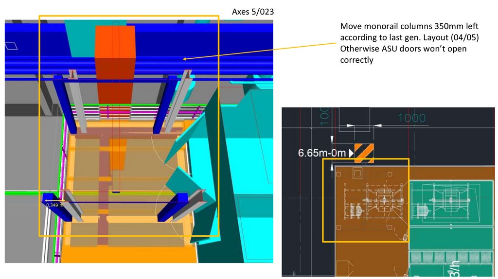
Axes 5/023 Move monorail columns 350mm left
1.
Axes 5/023Move monorail columns 350mm left
according to last gen. Layout (04/05)
Otherwise ASU doors won’t open
correctly
2.
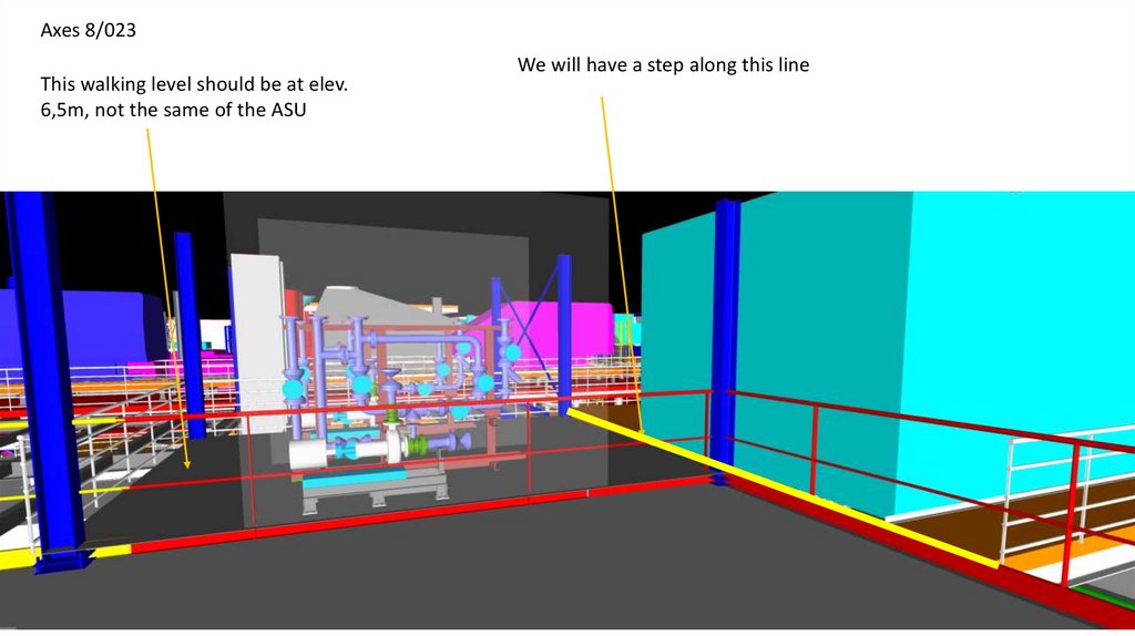
Axes 8/023This walking level should be at elev.
6,5m, not the same of the ASU
We will have a step along this line
3.
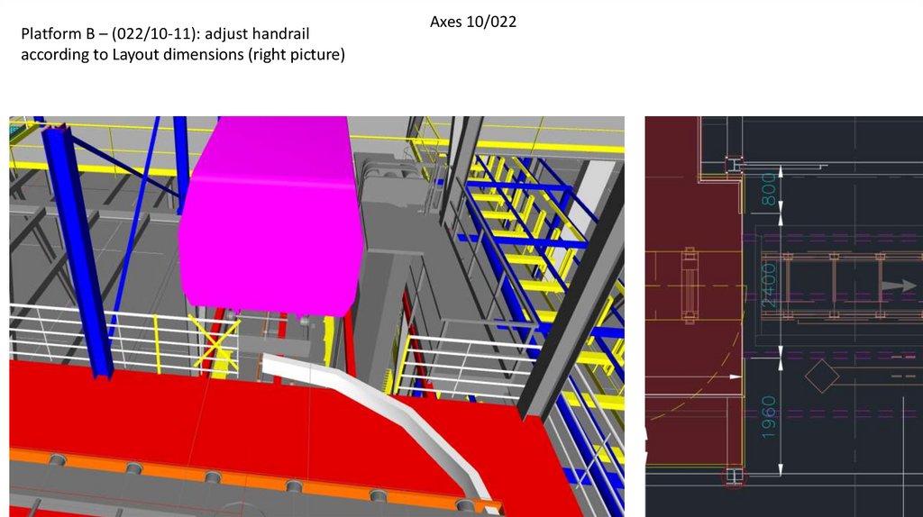
Platform B – (022/10-11): adjust handrailaccording to Layout dimensions (right picture)
Axes 10/022
4.
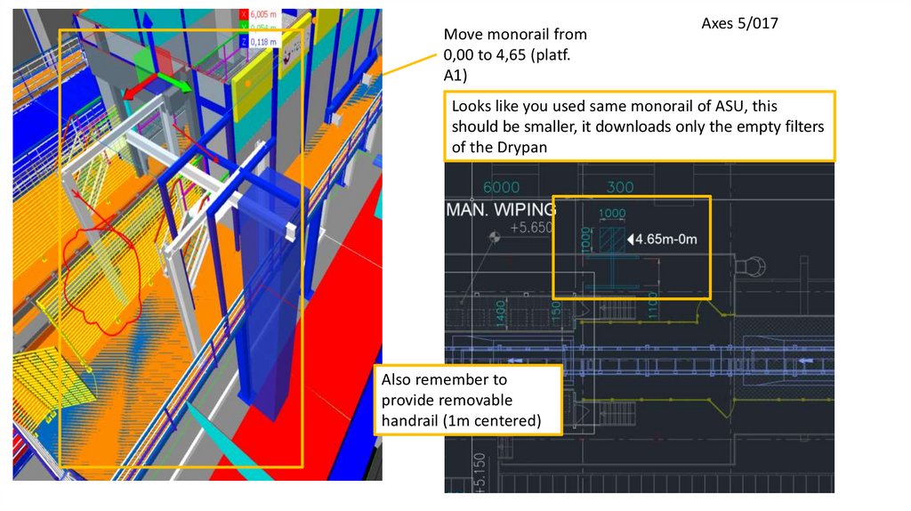
Move monorail from0,00 to 4,65 (platf.
A1)
Axes 5/017
Looks like you used same monorail of ASU, this
should be smaller, it downloads only the empty filters
of the Drypan
Also remember to
provide removable
handrail (1m centered)
5.
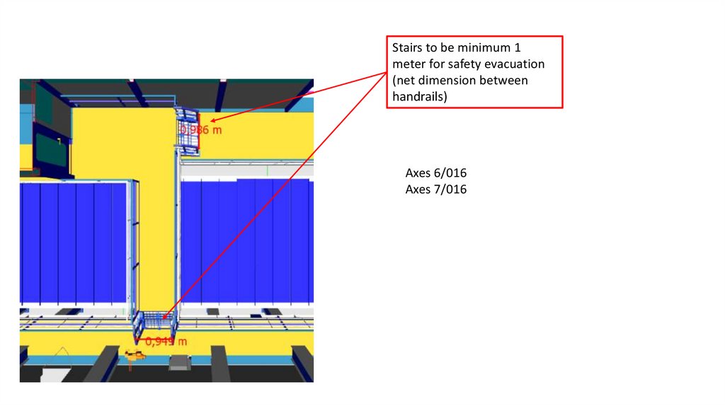
Stairs to be minimum 1meter for safety evacuation
(net dimension between
handrails)
Axes 6/016
Axes 7/016
6.
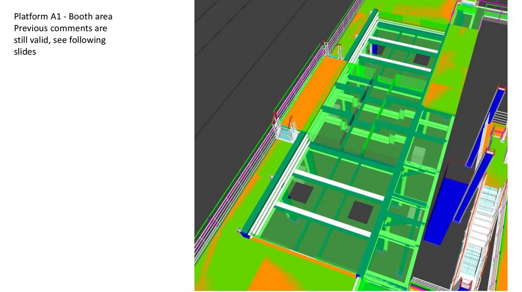
Platform A1 - Booth areaPrevious comments are
still valid, see following
slides
7.
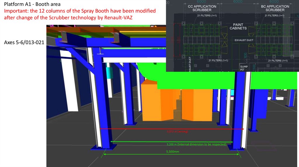
Platform A1 - Booth areaImportant: the 12 columns of the Spray Booth have been modified
after change of the Scrubber technology by Renault-VAZ
Axes 5-6/013-021
(wrong)
(Internal dimension to be respected)
5,500mm
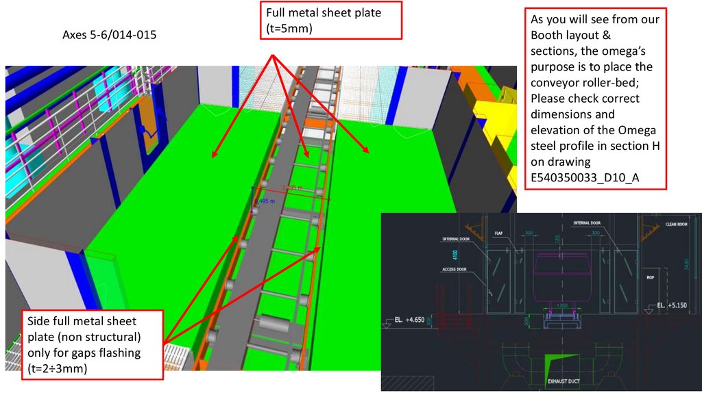
8.
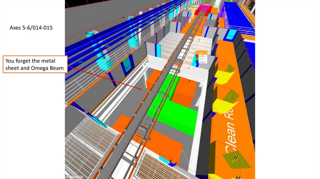
Axes 5-6/014-015You forget the metal
sheet and Omega Beam
9.
Axes 5-6/014-015Side full metal sheet
plate (non structural)
only for gaps flashing
(t=2÷3mm)
Full metal sheet plate
(t=5mm)
As you will see from our
Booth layout &
sections, the omega’s
purpose is to place the
conveyor roller-bed;
Please check correct
dimensions and
elevation of the Omega
steel profile in section H
on drawing
E540350033_D10_A
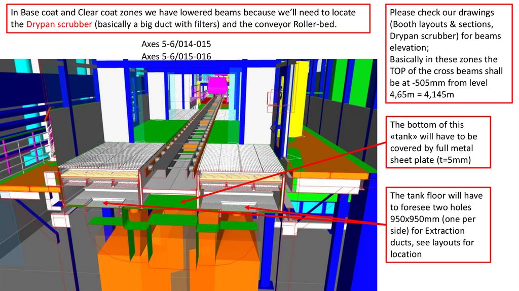
10.
In Base coat and Clear coat zones we have lowered beams because we’ll need to locatethe Drypan scrubber (basically a big duct with filters) and the conveyor Roller-bed.
Axes 5-6/014-015
Axes 5-6/015-016
Please check our drawings
(Booth layouts & sections,
Drypan scrubber) for beams
elevation;
Basically in these zones the
TOP of the cross beams shall
be at -505mm from level
4,65m = 4,145m
The bottom of this
«tank» will have to be
covered by full metal
sheet plate (t=5mm)
The tank floor will have
to foresee two holes
950x950mm (one per
side) for Extraction
ducts, see layouts for
location
11.
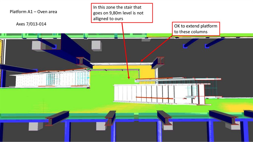
Platform A1 – Oven areaAxes 7/013-014
In this zone the stair that
goes on 9,80m level is not
alligned to ours
OK to extend platform
to these columns
12.
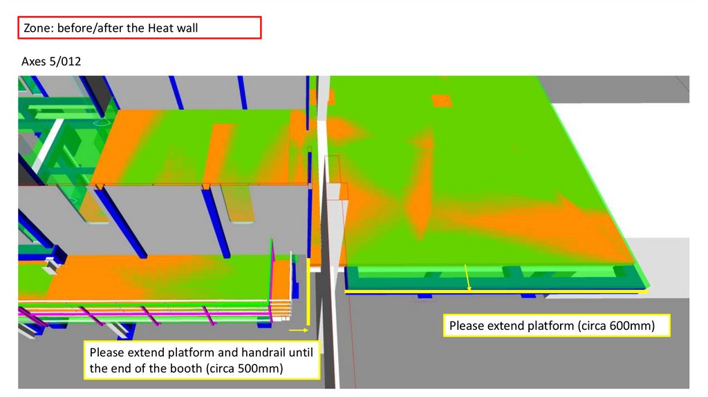
Zone: before/after the Heat wallAxes 5/012
Please extend platform (circa 600mm)
Please extend platform and handrail until
the end of the booth (circa 500mm)
13.
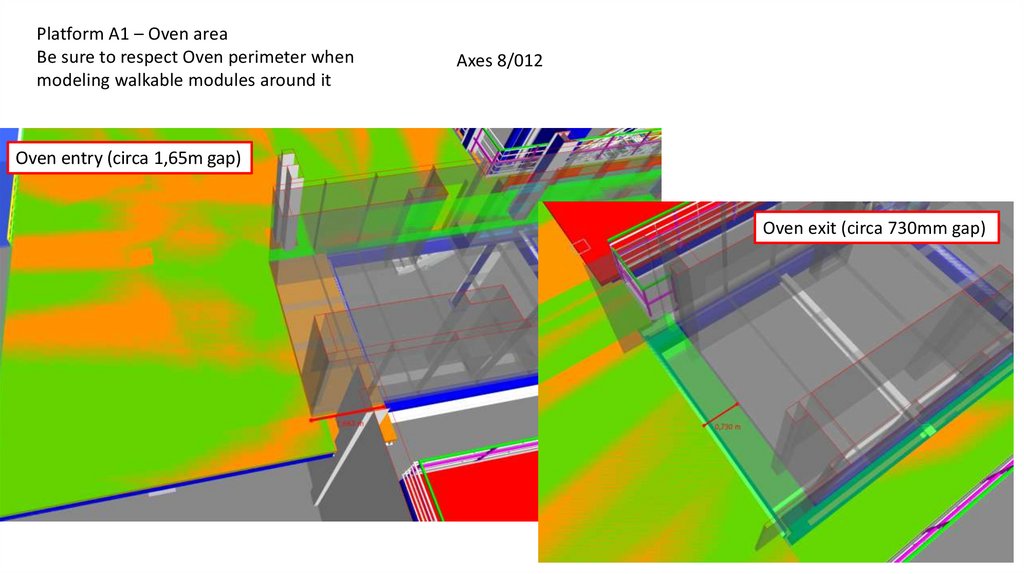
Platform A1 – Oven areaBe sure to respect Oven perimeter when
modeling walkable modules around it
Axes 8/012
Oven entry (circa 1,65m gap)
Oven exit (circa 730mm gap)
14.
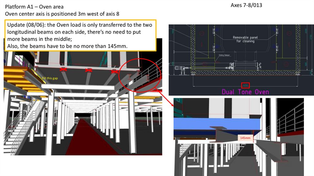
Platform A1 – Oven areaOven center axis is positioned 3m west of axis 8
Axes 7-8/013
Update (08/06): the Oven load is only transferred to the two
longitudinal beams on each side, there’s no need to put
more beams in the middle;
Also, the beams have to be no more than 145mm.
Fill this gap
145mm
15.
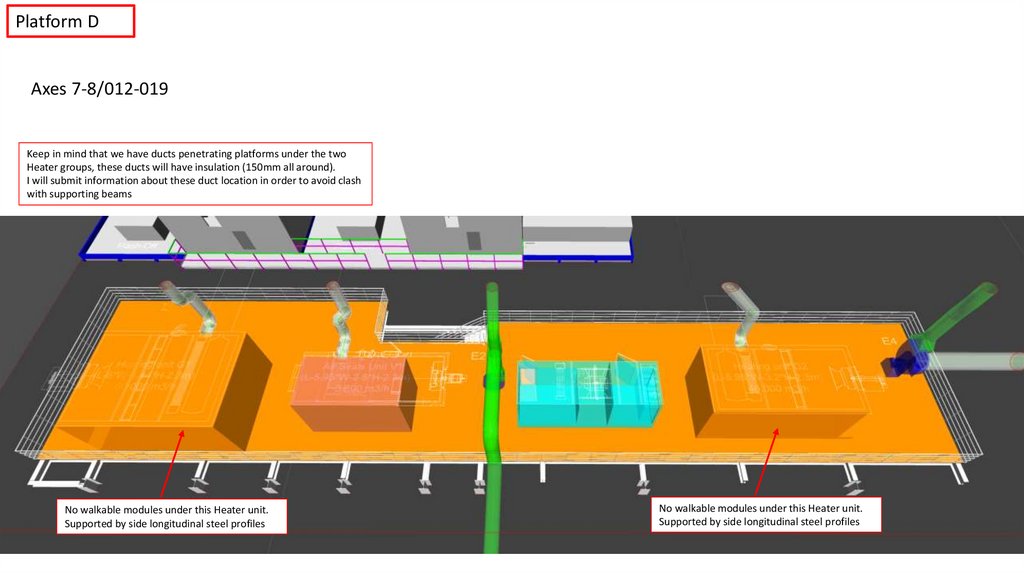
Platform DAxes 7-8/012-019
Keep in mind that we have ducts penetrating platforms under the two
Heater groups, these ducts will have insulation (150mm all around).
I will submit information about these duct location in order to avoid clash
with supporting beams
No walkable modules under this Heater unit.
Supported by side longitudinal steel profiles
No walkable modules under this Heater unit.
Supported by side longitudinal steel profiles
16.
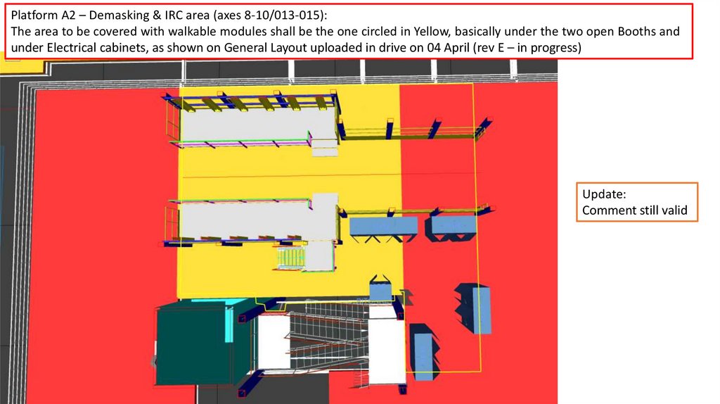
Platform A2 – Demasking & IRC area (axes 8-10/013-015):The area to be covered with walkable modules shall be the one circled in Yellow, basically under the two open Booths and
under Electrical cabinets, as shown on General Layout uploaded in drive on 04 April (rev E – in progress)
Update:
Comment still valid
17.
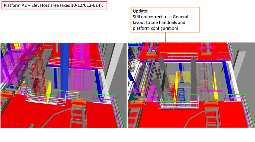
Platform A2 – Elevators area (axes 10-12/013-014):Update:
Still not correct, use General
layout to see handrails and
platform configuration!
18.
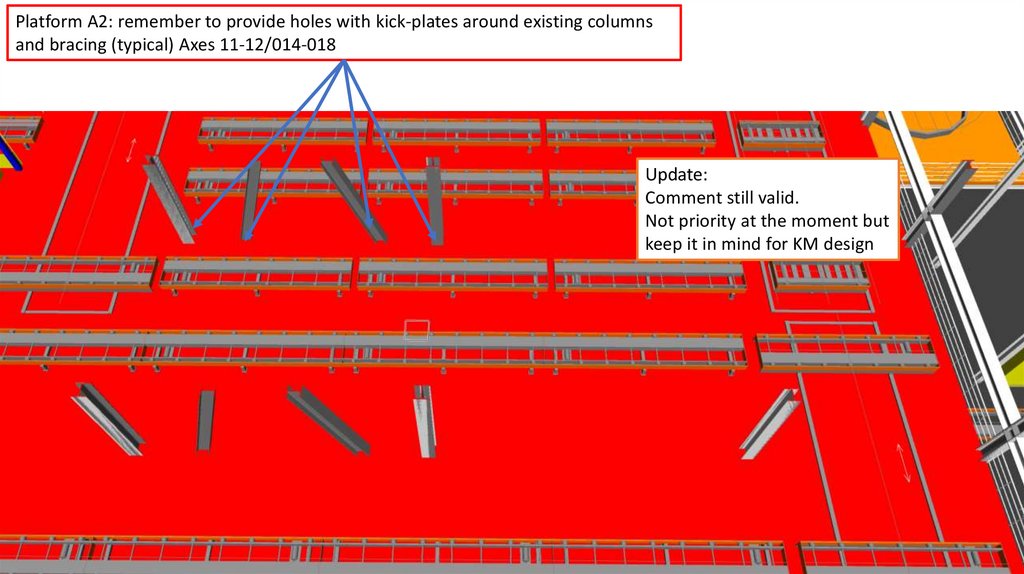
Platform A2: remember to provide holes with kick-plates around existing columnsand bracing (typical) Axes 11-12/014-018
Update:
Comment still valid.
Not priority at the moment but
keep it in mind for KM design
19.
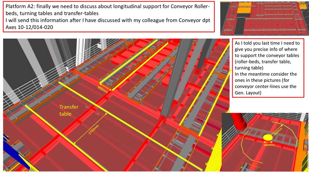
Platform A2: finally we need to discuss about longitudinal support for Conveyor Rollerbeds, turning tables and transfer-tablesI will send this information after I have discussed with my colleague from Conveyor dpt
Axes 10-12/014-020
As I told you last time I need to
give you precise info of where
to support the conveyor tables
(roller-beds, transfer table,
turning table)
In the meantime consider the
ones in these pictures (for
conveyor center-lines use the
Gen. Layout)
Transfer
table