
 industry
Similar presentations:


Key Engineering Materials
1.
Key Engineering MaterialsISSN: 1662-9795, Vol. 763, pp 50-60
doi:10.4028/www.scientific.net/KEM.763.50
© 2018 Trans Tech Publications, Switzerland
Buckling-Restrained Brace:
History, Design and Applications
Toru Takeuchi1,a
1
Tokyo Institute of Technology, 2-12-1-M1-29 Ookayama Meguro-ku Tokyo Japan
a
[email protected]
Keywords: Buckling-Restrained Brace, Research History, Buckling, Energy Dissipation
Abstract. Buckling-restrained braces (BRBs), which were first applied in 1989 in Japan, are now
widely used worldwide as ductile seismic-proof members in seismic zones, such as those in Japan,
USA, Taiwan, China, Turkey, and New Zealand. Although the design procedures of BRBs and their
applications are described in the design codes and recommendations of several countries, they do not
necessarily cover all the required aspects. Moreover, various new types of BRBs are still under
investigation by many researchers. In this paper, the early history of BRB research and development
and state-of-the-art views on the items required to design BRBs for obtaining stable hysteresis are
briefly overviewed. This is followed by a summary of various representative application concepts and
up-to-date investigations.
Introduction
The buckling-restrained brace (BRB) is a seismic device consisting of an axially yielding core
and axially decoupled restraining mechanism, which suppresses the overall buckling. The hysteretic
characteristics are stable and nearly symmetric once the full cross section of the core has yielded,
differing only slightly from the base material hysteresis. Because buckling is restrained, no associated
degradation should be appeared during the compression cycles. For this unique behavior, BRBs can
be modeled using truss elements and uniaxial material hysteresis rules, assuming strain is distributed
along the full plastic core length.
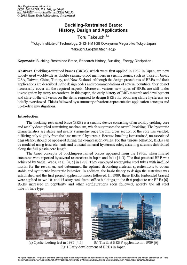
The basic concepts of buckling-restrained braces appeared from the 1970s, when limited
successes were reported by several researchers in Japan and India [1–3]. The first practical BRB was
achieved by Saeki, Wada, et al. [4, 5] in 1988. They employed rectangular steel tubes with in-filled
mortar for the restrainer, and determined the optimal debonding material specifications to obtain
stable and symmetric hysteretic behavior. In addition, the basic theory to design the restrainer was
established and the first project application soon followed. In 1989, these BRBs (unbonded braces)
were applied to two 10- and 15-story steel frame office buildings, in the first project to use BRBs [6].
BRBs increased in popularity and other configurations soon followed, notably the all steel
tube-in-tube type.
(a) Cyclic loading test in 1987 [4,5]
(b) The first BRBF application in 1989 [6]
Fig.1 Early development of BRBs in Japan.
All rights reserved. No part of contents of this paper may be reproduced or transmitted in any form or by any means without the written permission of Trans
Tech Publications, www.scientific.net. (#107365303, University of Michigan Library, Media Union Library, Ann Arbor, USA-05/03/18,15:26:33)
2.
Key Engineering Materials Vol. 76351
Through the 1990s, BRBs were used in approximately 160 buildings in Japan. In July 1995, the
concept of “damage tolerant structure” was proposed by Wada, Iwata, et al. [7], which uses BRBs as
energy dissipating elasto-plastic dampers within an elastic main frame. The AIJ design
recommendations included BRBs design guidelines for the first time in 1996 [8].
Collaboration with researchers in US soon led to the first international application, with the
construction of a building at UC Davis in 1998, followed by an experiment at UC Berkeley in
2000 [9]. Numerous other buildings with BRBs were soon constructed throughout California,
including some in seismic retrofit applications. In 2002, a design guidance for the buckling-restrained
braced frame (BRBF) was included in the Seismic Provisions for Structural Steel Buildings
(ANSI/AISC 341-05) [10]. During these early years of technology transfer to international markets, a
series of symposiums on passively controlled structures were held at Tokyo Tech, sharing code
developments, BRB designs, and novel applications [11]. Through the following decade, BRBs
increased in popularity in numerous countries, from Taiwan in the early 2000s [12] to the recent
implementations in New Zealand as part of the Christchurch rebuild. BRBs are now widely known in
seismic areas throughout the world, with research ongoing in countries such as Japan, Taiwan, China,
USA, Canada, Turkey, Iran, Italy, Romania, New Zealand, and Chile.
Requirements for Stable Hysteresis
In general, the BRB must be designed for strength and stability, considering both its local and
global behavior, as shown in Fig. 2.
Restrainer
Global Stability, including:
Connections
Restrainer End
Higher Mode
Buckling
Connection
Strength
Fatigue
Fig.2 BRB stability and strength.
Fracture
To obtain a stable hysteresis, the following design conditions shall be basically satisfied [8].
1. The Restrainer successfully suppresses first-mode flexural buckling of the core
2. The Debonding mechanism decouples axial demands and allows for Poisson effects of the core
3. The Restrainer wall bulging owing to higher mode buckling is suppressed
4. Global out-of-plane stability is ensured, including connections
5. Low-cycle fatigue capacity is sufficient for the expected demands
For designing the restrainer to suppress the global buckling of the core, the restrainer flexural
yield strength MBy should satisfy [13]:
=
MB
N cu ( a + 2 sr + e )
N cu ac
=
≤ M yB
E
E
1 − N cu N cr
1 − N cu N cr
(1)
where a fabrication imperfection of core and/or brace, sr clearance or thickness of debonding
material (per face), e eccentricity of the axial force, MBy flexural strength of the restrainer,
Ncu = d αNy core yield strength amplified by overstrength and strain hardening, and NEcr Euler
buckling strength of the restrainer, which is given by:
3.
52Behaviour of Steel Structures in Seismic Areas
N crE =
π 2 EI B
(2)
lB 2
For the case of initial imperfections ac/lB ≤ 1/500, a relatively slender restrainer with lB/Dr > 20 and
with an overall safety factor of eα ≥ 1.5, Eq.(1) can be reduced to Eq.(3).
=
N crB
π 2 EI B
> e α N cu
lB 2
(3)
The purpose of the debonding layer is to prevent significant compressive loads from being
passed to the restrainer, preventing it from buckling and ensuring a balance hysteresis. This is
achieved by introducing a low friction interface and by accommodating the Poisson effect expansion
of the core under compressive loads, either through the provision of a suitable gap or a compressible
material or through elastic deformation of the restrainer material. However, the gap must be closely
controlled as it is directly related to the higher mode buckling amplitude.
sr ≥
ν pε max Bc
(per face)
2
(4)
where sr : appropriate clearance, νp : the plastic Poisson ratio (= 0.5), εmax : maximum expected tensile
strain, and Bc : core width.
Local Bulging Failure
The compressible debonding layer between the steel core and restrainer provides a space for the
flat steel core to form high mode buckling waves when the BRB is under compression. An in-plane or
out-of-plane local bulging failure would occur if the steel tube strength is insufficient to sustain the
in-plane or out-of-plane outward force. To avoid local bulging failure, the following criteria should
be satisfied [14–18, 44].
Pd ,s
( Dr − tc ) ⋅ 4 N cu ( 2srs +ν p Bcε t ) < 1.0
=
DCRs =
Pc ,s ( 2 Dr − tc ) tr2s ry
l p ,s
(5)
Pd ,w
( Br − Bc ) ⋅ 4 N cu ( 2srw +ν ptcε t ) < 1.0
DCRw =
=
Pc ,w ( 2 Br − Bc ) tr2s ry
l p ,w
(6)
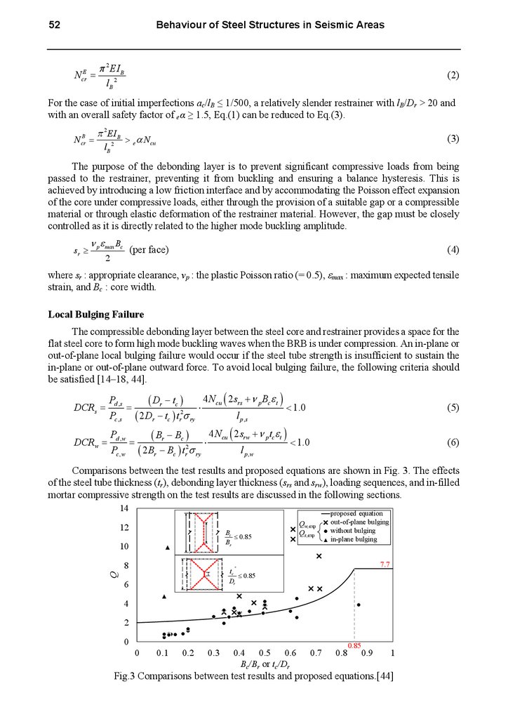
Comparisons between the test results and proposed equations are shown in Fig. 3. The effects
of the steel tube thickness (tr), debonding layer thickness (srs and srw), loading sequences, and in-filled
mortar compressive strength on the test results are discussed in the following sections.
14
proposed equation
12
Bc
≤ 0.85
Br
10
Q
8
proposed
equation
out-of-plane
bulging
Qw,exp
out-of-plan
bulging
bulging
Qs,exp corewithout
fracturebulging
in-plane
in-plan bulging
p
tc
≤ 0.85
Dr
6
7.7
4
2
0
0
0.1
0.2
0.3
0.4 0.5 0.6
Bc/Br or tc/Dr
0.7
0.8
0.85
0.9
1
Fig.3 Comparisons between test results and proposed equations.[44]
4.
Key Engineering Materials Vol. 763When the in-filled mortar in the restrainer does not have enough strength, it could be crushed by
the acting outward forces. If the contact surface is Bc long and lc wide, the criterion could be
expressed as in Eq. (7):
Pd , w
lc Bc
< f c'
(7)
where f’c is the allowable compressive strength of the in-filled mortar. Although the value of lc
requires additional research, it can be estimated generally as lc ≈ tc.
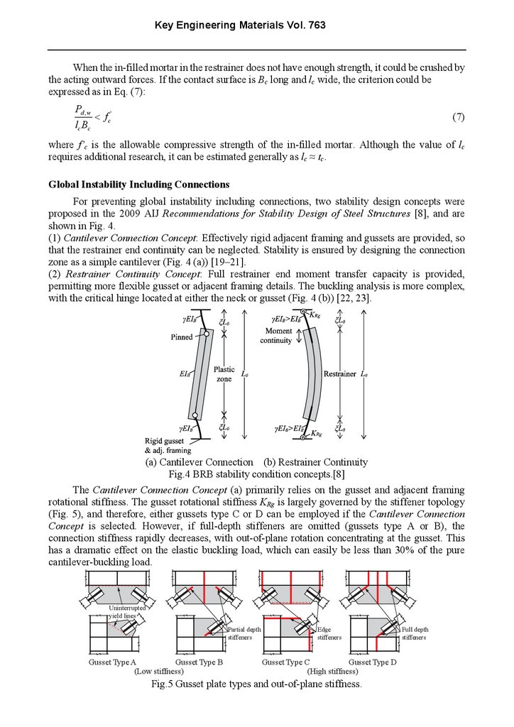
Global Instability Including Connections
For preventing global instability including connections, two stability design concepts were
proposed in the 2009 AIJ Recommendations for Stability Design of Steel Structures [8], and are
shown in Fig. 4.
(1) Cantilever Connection Concept: Effectively rigid adjacent framing and gussets are provided, so
that the restrainer end continuity can be neglected. Stability is ensured by designing the connection
zone as a simple cantilever (Fig. 4 (a)) [19–21].
(2) Restrainer Continuity Concept: Full restrainer end moment transfer capacity is provided,
permitting more flexible gusset or adjacent framing details. The buckling analysis is more complex,
with the critical hinge located at either the neck or gusset (Fig. 4 (b)) [22, 23].
(a) Cantilever Connection (b) Restrainer Continuity
Fig.4 BRB stability condition concepts.[8]
The Cantilever Connection Concept (a) primarily relies on the gusset and adjacent framing
rotational stiffness. The gusset rotational stiffness KRg is largely governed by the stiffener topology
(Fig. 5), and therefore, either gussets type C or D can be employed if the Cantilever Connection
Concept is selected. However, if full-depth stiffeners are omitted (gussets type A or B), the
connection stiffness rapidly decreases, with out-of-plane rotation concentrating at the gusset. This
has a dramatic effect on the elastic buckling load, which can easily be less than 30% of the pure
cantilever-buckling load.
Uninterrupted
yield lines
Partial depth
stiffeners
Gusset Type A
Gusset Type B
(Low stiffness)
Edge
stiffeners
Gusset Type C
Gusset Type D
(High stiffness)
Fig.5 Gusset plate types and out-of-plane stiffness.
Full depth
stiffeners
5.
54Behaviour of Steel Structures in Seismic Areas
The Restrainer Continuity Concept described in Fig. 4 (b) is based on the analysis of the full BRB
with continuity provided at the restrainer ends. Although several design equations have been
proposed, the Takeuchi’s proposal in 2014 [22] provides the most general criteria.
=
N lim1
(M
(M
r
p
r
p
− M 0r ) ar + N crr
− M 0r ) ar N crB + 1
> N cu
(8)
where Nrcr is the elasto-plastic buckling load of NRcr, and M p − M 0 should be taken as zero if the
difference is negative. The criteria when the gusset produces plastic hinges are given as follows:
r
N lim 2
r
(1 − 2ξ ) M pg + M pr − 2 M 0r ar
> N cu
(1 − 2ξ ) M pg + M pr − 2 M 0r (ar N crB ) + 1
(9)
where M pg is the plastic bending strength of the gusset plate including the axial force effect, and
(1 − 2ξ ) M pg − M 0r or M pr − M 0r should be taken as zero if the difference is negative. The minimum
value of Nlim1 and Nlim2 is defined as the stability limit Nlim, which should be smaller than Ncu.
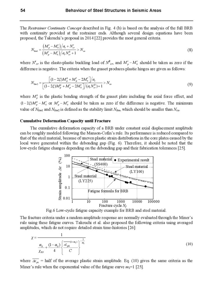
Cumulative Deformation Capacity until Fracture
Strain amplitude ∆ε (%)
The cumulative deformation capacity of a BRB under constant axial displacement amplitude
can be roughly modeled following the Manson-Cofin’s rule. Its performance is reduced compared to
that of the steel material, because of uneven plastic strain distributions in the core plates caused by the
local wave generated within the debonding gap (Fig. 6). Therefore, it should be noted that the
low-cycle fatigue changes depending on the debonding gap and their fabrication tolerances [25].
100
Steel material
(SS400)
10
1
Steel material
(LY225)
Experimental result1)
Steel material
(LY100)
0.1
Fatigue formula for BRB
Eqs. (1) and (2)
0.01
1
10
100
1000
10000 100000
Fracture cycle Nf
Fig.6 Low-cycle fatigue capacity example for BRB and steel material.
The fracture criteria under a random amplitude response are normally evaluated through the Miner’s
rule using these fatigue curves. Takeuchi et al. also proposed the following criteria using averaged
amplitudes, which do not require detailed strain time-histories [26]:
χ=
1
(1+ m2 )
αS (1 − αS ) ∆ε ph
+
χ SO
4 C
−
1
m2
(10)
where ∆ε ph = half of the average plastic strain amplitude. Eq. (10) gives the same criteria as the
Miner’s rule when the exponential value of the fatigue curve m2=1 [25].
6.
Key Engineering Materials Vol. 76355
Performance Test Specification for BRB
Although the axial yielding mechanism of BRBs is conceptually simple, its performance
depends on the precise detailing of the debonding mechanism and restrainer, and is sensitive to
fabrication quality. To ensure that a BRB will perform as intended, most jurisdictions require
physical testing, either as part of a supplier prequalification or on a project-specific basis. It is
important that the test specimens be fabricated by the appointed manufacturer, be of similar
proportions, and use the same details as those used in the design. The detailed specifications are
described in AISC 341-16 [10] and the Building Center of Japan (BCJ), whose testing protocols are
summarized in tables. The detailed requirements of testing are described in [44].
BRBF Applications
Various structural design concepts using BRBs have been proposed and realized over these
30 years. Some of them are introduced below.
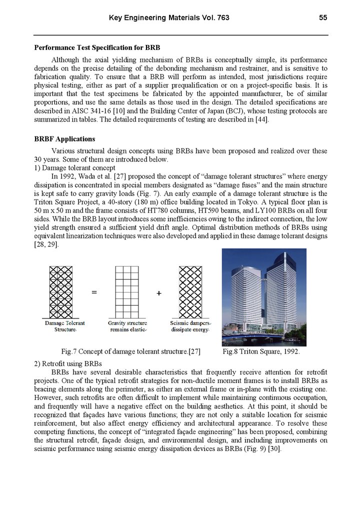
1) Damage tolerant concept
In 1992, Wada et al. [27] proposed the concept of “damage tolerant structures” where energy
dissipation is concentrated in special members designated as “damage fuses” and the main structure
is kept safe to carry gravity loads (Fig. 7). An early example of a damage tolerant structure is the
Triton Square Project, a 40-story (180 m) office building located in Tokyo. A typical floor plan is
50 m x 50 m and the frame consists of HT780 columns, HT590 beams, and LY100 BRBs on all four
sides. While the BRB layout introduces some inefficiencies owing to the indirect connection, the low
yield strength ensured a sufficient yield drift angle. Optimal distribution methods of BRBs using
equivalent linearization techniques were also developed and applied in these damage tolerant designs
[28, 29].
Fig.7 Concept of damage tolerant structure.[27]
Fig.8 Triton Square, 1992.
2) Retrofit using BRBs
BRBs have several desirable characteristics that frequently receive attention for retrofit
projects. One of the typical retrofit strategies for non-ductile moment frames is to install BRBs as
bracing elements along the perimeter, as either an external frame or in-plane with the existing one.
However, such retrofits are often difficult to implement while maintaining continuous occupation,
and frequently will have a negative effect on the building aesthetics. At this point, it should be
recognized that façades have various functions; they are not only a suitable location for seismic
reinforcement, but also affect energy efficiency and architectural appearance. To resolve these
competing functions, the concept of “integrated façade engineering” has been proposed, combining
the structural retrofit, façade design, and environmental design, and including improvements on
seismic performance using seismic energy dissipation devices as BRBs (Fig. 9) [30].
7.
56Behaviour of Steel Structures in Seismic Areas
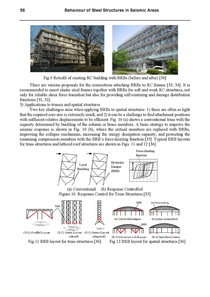
Fig.9 Retrofit of existing RC building with BRBs (before and after).[30]
There are various proposals for the connections attaching BRBs to RC frames [33, 34]. It is
recommended to insert elastic steel frames together with BRBs for soft and weak RC structures, not
only for reliable sheer force transition but also for providing self-centering and damage distribution
functions [31, 32].
3) Applications to trusses and spatial structures
Two key challenges arise when applying BRBs to spatial structures: 1) these are often so light
that the required core size is extremely small, and 2) it can be a challenge to find attachment positions
with sufficient relative displacements to be efficient. Fig. 10 (a) shows a conventional truss with the
capacity determined by buckling of the column or brace members. A basic strategy to improve the
seismic response is shown in Fig. 10 (b), where the critical members are replaced with BRBs,
improving the collapse mechanism, increasing the energy dissipation capacity, and protecting the
remaining compression members with the BRB’s force-limiting function [35]. Typical BRB layouts
for truss structures and latticed roof structures are shown in Figs. 11 and 12 [36].
Force-limiting
function
Local
Buckling
Hysteretic
Damper
(BRB)
(a) Conventional (b) Response Controlled
Figure 10 Response Control for Truss Structures.[35]
Fig.11 BRB layout for truss structures.[36]
Fig.12 BRB layout for spatial structures.[36]
8.
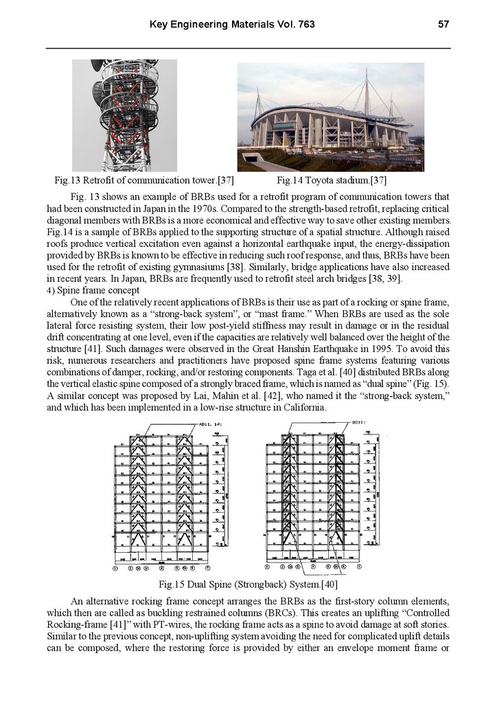
Key Engineering Materials Vol. 763Fig.13 Retrofit of communication tower.[37]
57
Fig.14 Toyota stadium.[37]
Fig. 13 shows an example of BRBs used for a retrofit program of communication towers that
had been constructed in Japan in the 1970s. Compared to the strength-based retrofit, replacing critical
diagonal members with BRBs is a more economical and effective way to save other existing members.
Fig.14 is a sample of BRBs applied to the supporting structure of a spatial structure. Although raised
roofs produce vertical excitation even against a horizontal earthquake input, the energy-dissipation
provided by BRBs is known to be effective in reducing such roof response, and thus, BRBs have been
used for the retrofit of existing gymnasiums [38]. Similarly, bridge applications have also increased
in recent years. In Japan, BRBs are frequently used to retrofit steel arch bridges [38, 39].
4) Spine frame concept
One of the relatively recent applications of BRBs is their use as part of a rocking or spine frame,
alternatively known as a “strong-back system”, or “mast frame.” When BRBs are used as the sole
lateral force resisting system, their low post-yield stiffness may result in damage or in the residual
drift concentrating at one level, even if the capacities are relatively well balanced over the height of the
structure [41]. Such damages were observed in the Great Hanshin Earthquake in 1995. To avoid this
risk, numerous researchers and practitioners have proposed spine frame systems featuring various
combinations of damper, rocking, and/or restoring components. Taga et al. [40] distributed BRBs along
the vertical elastic spine composed of a strongly braced frame, which is named as “dual spine” (Fig. 15).
A similar concept was proposed by Lai, Mahin et al. [42], who named it the “strong-back system,”
and which has been implemented in a low-rise structure in California.
Fig.15 Dual Spine (Strongback) System.[40]
An alternative rocking frame concept arranges the BRBs as the first-story column elements,
which then are called as buckling restrained columns (BRCs). This creates an uplifting “Controlled
Rocking-frame [41]” with PT-wires, the rocking frame acts as a spine to avoid damage at soft stories.
Similar to the previous concept, non-uplifting system avoiding the need for complicated uplift details
can be composed, where the restoring force is provided by either an envelope moment frame or
9.
58Behaviour of Steel Structures in Seismic Areas
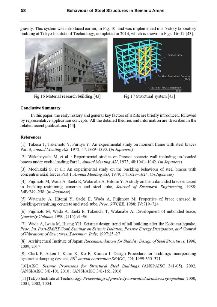
gravity. This system was introduced earlier, in Fig. 10, and was implemented in a 5-story laboratory
building at Tokyo Institute of Technology, completed in 2014, which is shown in Figs. 16–17 [43].
Fig.16 Material research building.[43]
Fig.17 Structural system.[43]
Conclusive Summary
In this paper, the early history and general key factors of BRBs are briefly introduced, followed
by representative application concepts. All the detailed theories and information are described in the
related recent publications [44].
References
[1] Takeda T, Takemoto Y, Furuya Y: An experimental study on moment frame with steel braces
Part 3, Annual Meeting AIJ, 1972; 47:1389–1390. (in Japanese)
[2] Wakabayashi M, et al. : Experimental studies on Precast concrete wall including un-bonded
braces under cyclic loading Part 1, Annual Meeting AIJ, 1973; 48:1041–1042. (in Japanese)
[3] Mochizuki S, et al.: An experimental study on the buckling behaviour of steel braces with
concentric axial forces Part 1, Annual Meeting AIJ, 1979; 54:1623–1624. (in Japanese)
[4] Fujimoto M, Wada A, Saeki E, Watanabe A, Hitomi Y: A study on the unbounded brace encased
in buckling-restraining concrete and steel tube, Journal of Structural Engineering, 1988;
34B:249–258. (in Japanese)
[5] Watanabe A, Hitomi Y, Saeki E, Wada A, Fujimoto M: Properties of brace encased in
buckling-restraining concrete and steel tube, Proc. 9WCEE, 1988; IV:719–724.
[6] Fujimoto M, Wada A, Saeki E, Takeuchi T, Watanabe A: Development of unbonded brace,
Querterly Column, 1990; (115):91–96.
[7] Wada A, Iwata M, Huang YH: Seismic design trend of tall building after the Kobe earthquake,
Proc. Int. Post-SMiRT Conf. Seminar on Seismic Isolation, Passive Energy Dissipation, and Control
of Vibrations of Structures, Taormina, Italy; 1997:25–27
[8] Architectural Institute of Japan: Recommendations for Stability Design of Steel Structures, 1996,
2009, 2017
[9] Clark P, Aiken I, Kasai K, Ko E, Kimura I: Design Procedure for buildings incorporating
hysteretic damping devices, 68th annual convention SEAOC, CA; 1999:355–371.
[10] AISC: Seismic Provisions for Structural Steel Buildings (ANSI/AISC 341-05), 2002,
(ANSI/AISC 341-10), 2010 , (ANSI/AISC 341-16), 2016
[11] Tokyo Institute of Technology: Proceedings of passively controlled structures symposium; 2000,
2001, 2002, 2004.
10.
Key Engineering Materials Vol. 763[12] Tsai KC, Lai JW, Hwang YC , Lin SL, Weng CH: Research and application of double-core
buckling-restrained braces in Taiwan, 13WCEE 2004:Paper No. 2179.
[13] Wada A, Nakashima M: From infancy to maturity of buckling restrained braces research,
Proceedings of 13WCEE, 2004; (1732).
[14] Takeuchi T., Hajjar JF, Matsui R., Nishimoto K, and Aiken ID: Local buckling resistant
condition for core plates in buckling restrained braces, Journal of Constructional Steel Research,
2010; 66(2):139–149.
[15]
Lin PC, Tsai KC, Chang CA, Hsiao YY, Wu AC: Seismic design and testing of
buckling-restrained braces with a thin profile, Earthquake Engineering and Structural Dynamics,
2016; 45(3):339–358.
[16]
Wu AC, Lin PC, and Tsai KC: High-mode buckling responses of buckling-restrained brace
core plates, Earthquake Engineering and Structural Dynamics, 2013; 43(3):375–393.
[17] Yoshida F, Okamoto Y, Murai M, Iwata M: A study on local failure of buckling restrained
braces using steel mortar planks (Part-1: local failure), Annual Meeting AIJ, 2010; C-1, Structure
III:961–962. (in Japanese)
[18] Takeuchi T, Hajjar JF, Matsui R, Nishimoto K, Aiken ID: Effect of local buckling core plate
restraint in buckling restrained braces, Engineering Structures, 2012; 44:304–311.
[19] Tsai KC, Huang YC, Weng CS, Shirai T, Nakamura H: Experimental tests of large scale
buckling restrained braces and frames. Proceedings, 2nd Passive Control Symposium, Tokyo Institute
of Technology, 2002.
[20] Koetaka Y, Kinoshita T, Inoue K, Iitani K: Criteria of buckling-restrained braces to prevent
out-of-plane buckling. Proc. 14WCEE, 2008.
[21] Hikino T, Okazaki T, Kajiwara K, Nakashima M: Out-of-Plane stability of buckling-restrained
braces placed in chevron arrangement. Journal of Structural Engineering, ASCE, 2013; 139(11)
[22] Takeuchi T, Ozaki H, Matsui R, Sutcu F: Out-of-plane stability of buckling-restrained braces
including moment transfer capacity. Earthquake Engineering & Structural Dynamics, 2014;
43(6):851–869,
[23] Takeuchi T, Matsui R, Mihara S: Out-of-plane stability assessment of buckling-restrained braces
including connections with chevron configuration. Earthquake Engineering & Structural Dynamics,
2016; 45(12):1895–1917
[24] Nakamura H, Takeuchi T, Maeda Y, Nakata Y, Sasaki T, Iwata M, Wada A: Fatigue properties
of practical-scale unbonded braces. Nippon steel Technical Report, 2000; (82):51–57.
[25] Matsui R, Takeuchi T: Cumulative deformation capacity of buckling restrained braces taking
local buckling of core plates into account. Proc. 15WCEE, 2012.
[26] Takeuchi T, Ida M, Yamada S, Suzuki K: Estimation of cumulative deformation capacity of
buckling restrained braces. ASCE Journal of Structural Engineering, 2008; 134(5):822–831.
[27] Wada A, Connor J, Kawai H, Iwata M, Watanabe A: Damage tolerant structure, ATC-15-4, Proc.
5th US-Japan WS on the Imprement of Building Structural Design and Construction Practices, 1992
[28] Kasai K, Fu Y, Watanabe A: Two types of passive control systems for seismic damage
mitigation, Journal of Structural Engineering, ASCE, 1998
[29] Japan Society of Seismic Isolation: Passive response control design manual, 2nd edition, 2005
(in Japanese and Chinese)
[30] Takeuchi T, Yasuda K, Iwata M: studies on integrated building façade engineering with
high-performance structural elements, IABSE 2006, 442–443
11.
60Behaviour of Steel Structures in Seismic Areas
[31] Sutcu F, Takeuchi T, Matsui R: Seismic retrofit design method for RC buildings using
buckling-restrained braces and steel frames. Journal of Constructional Steel Research, 2014;
101:304–313.
[32] Fujishita K, Sutcu F, Matsui R, Takeuchi T: Damage distribution based energy-dissipation
retrofit method for multi-story RC building in Turkey, Proc. IABSE, 2015
[33] Qu Z, Kishiki S, Maida Y, Sakata H., Wada A: Seismic responses of reinforced concrete frames
with buckling restrained braces in zigzag configuration. Engineering Structures, 2015; 105:12–21.
[34] Qu Z, Xie JJ, Wang T, Kishiki S: Cyclic loading test of double K-braced reinforced concrete
frame subassemblies with buckling restrained braces. Engineering Structures, 2017; 139:1–14.
[35]Takeuchi T, Suzuki K: Performance-based design for truss-frame structures using energy
dissipation devices, STESSA, 2003
[36] Takeuchi T, Xue SD, Nakazawa S, Kato S: Recent applications of response control techniques to
metal spatial structures, Journal of IASS, 2012; 53(2), n.172:99–110.
[37] Takeuchi T: Retrofit of damaged gymnasia and towers according to response control concept,
Proceedings of 10CUEE, 2013:17–24.
[38] Usami T, Lu Z, Ge H: A seismic upgrading method for steel arch bridges using buckling -restrained
Braces, Earthquake Engineering and Structural Dynamics, 2005; 34(4-5, 10-25):471–496.
[39] Celik O, Bruneau M: Skewed slab-on-girder steel bridge superstructures with bidirectional
-ductile end diaphragms, ASCE Journal of Bridge Engineering, 2011; 16(2):207–218
[40] Taga K, Koto M, Tokuda Y, Tsuruta J, Wada A: Hints on how to design passive control structure
whose damper efficiency is enhanced, and practicality of this structure, Proc. Passive Control
Symposium 2004, 105-112, Tokyo Tech, 2004.11
[41] Deierlein G, Ma X, Eatherton M, Hajjar J, Krawinkler H, Takeuchi T, Kasai K, Midorikawa M:
Earthquake resilient steel braced frames with controlled rocking and energy dissipating fuses.
EUROSTEEL, 2011
[42] Lai J, Mahin S: Strongback system: A way to reduce damage concentration in steel-braced
frames, Journal of Structural Engineering, Vol. 141(9), 2014
[43] Takeuchi T, Chen X, Matsui R: Seismic performance of controlled spine frames with
energy-dissipating members, Journal of Constructional Steel Research, Vol.115, 51–65, 2015.11
[44] Takeuchi T, Wada A: Buckling-restrained braces and applications, JSSI, 2017