 industry
Similar presentations:


Specifying Buckling-Restrained Brace Systems
1.
steelwiseSpecifying Buckling-Restrained Brace Systems
By kimberley robinson, s.e.
Using the ductility of steel effectively in concentrically braced frames.
The term buckling-restrained brace (BRB) has
become more common in the past few years, appearing in
construction magazine articles and conference presentations.
The system, the buckling-restrained braced frame (BRBF),
has been used more frequently in seismic applications.
The 2008 AISC T.R. Higgins lectureship awardees were
honored for their paper on the topic. BRBFs are a codified
system covered by both ASCE/SEI 7-05 and ANSI/AISC 34105. Yet even after so much recent information has appeared on
this topic, many engineers still ask: “What is a BRB? Why
consider using a BRBF? How do you specify this system?”
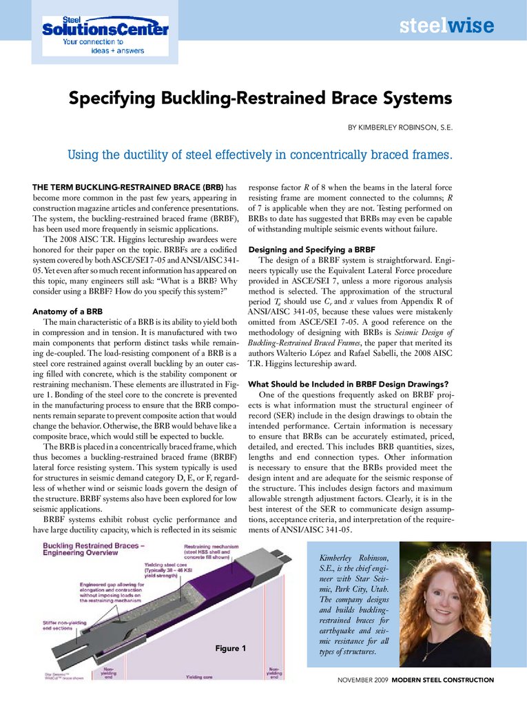
Anatomy of a BRB
The main characteristic of a BRB is its ability to yield both
in compression and in tension. It is manufactured with two
main components that perform distinct tasks while remaining de-coupled. The load-resisting component of a BRB is a
steel core restrained against overall buckling by an outer casing filled with concrete, which is the stability component or
restraining mechanism. These elements are illustrated in Figure 1. Bonding of the steel core to the concrete is prevented
in the manufacturing process to ensure that the BRB components remain separate to prevent composite action that would
change the behavior. Otherwise, the BRB would behave like a
composite brace, which would still be expected to buckle.
The BRB is placed in a concentrically braced frame, which
thus becomes a buckling-restrained braced frame (BRBF)
lateral force resisting system. This system typically is used
for structures in seismic demand category D, E, or F, regardless of whether wind or seismic loads govern the design of
the structure. BRBF systems also have been explored for low
seismic applications.
BRBF systems exhibit robust cyclic performance and
have large ductility capacity, which is reflected in its seismic
Figure 1
response factor R of 8 when the beams in the lateral force
resisting frame are moment connected to the columns; R
of 7 is applicable when they are not. Testing performed on
BRBs to date has suggested that BRBs may even be capable
of withstanding multiple seismic events without failure.
Designing and Specifying a BRBF
The design of a BRBF system is straightforward. Engineers typically use the Equivalent Lateral Force procedure
provided in ASCE/SEI 7, unless a more rigorous analysis
method is selected. The approximation of the structural
period Ta should use Cr and x values from Appendix R of
ANSI/AISC 341-05, because these values were mistakenly
omitted from ASCE/SEI 7-05. A good reference on the
methodology of designing with BRBs is Seismic Design of
Buckling-Restrained Braced Frames, the paper that merited its
authors Walterio López and Rafael Sabelli, the 2008 AISC
T.R. Higgins lectureship award.
What Should be Included in BRBF Design Drawings?
One of the questions frequently asked on BRBF projects is what information must the structural engineer of
record (SER) include in the design drawings to obtain the
intended performance. Certain information is necessary
to ensure that BRBs can be accurately estimated, priced,
detailed, and erected. This includes BRB quantities, sizes,
lengths and end connection types. Other information
is necessary to ensure that the BRBs provided meet the
design intent and are adequate for the seismic response of
the structure. This includes design factors and maximum
allowable strength adjustment factors. Clearly, it is in the
best interest of the SER to communicate design assumptions, acceptance criteria, and interpretation of the requirements of ANSI/AISC 341-05.
Kimberley Robinson,
S.E., is the chief engineer with Star Seismic, Park City, Utah.
The company designs
and builds bucklingrestrained braces for
earthquake and seismic resistance for all
types of structures.
november 2009 MODERN STEEL CONSTRUCTION
2.
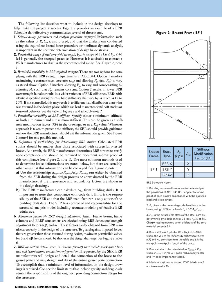
The following list describes what to include in the design drawings tohelp make the project a success. Figure 2 provides an example of a BRB
Schedule that effectively communicates several of these items.
1. Seismic design parameters and analysis procedure employed. Information such
as the values of R, Cd, I, and ρ used, and that the analysis was conducted
using the equivalent lateral force procedure or nonlinear dynamic analysis,
is important in the accurate determination of design brace strains.
2. Permissible range of steel core yield strength, Fysc. A range of 38 ksi ≤ Fysc ≤ 46
ksi is generally the accepted practice. However, it is advisable to contact a
BRB manufacturer to discuss the recommended range. See Figure 2, note
3.
3. Permissible variability in BRB required strength. There are two options for complying with the BRB strength requirements in AISC 341. Option 1 involves
maintaining a constant steel core area (Asc) and allowing Fysc (and Pysc) to vary
as stated above. Option 2 involves allowing Fysc to vary and compensating by
adjusting Asc such that Pysc remains constant. Option 2 results in lower BRB
overstrength but also results in a wider variation of BRB stiffnesses. BRBs with
identical specified strengths may have stiffnesses that vary by as much as 15 to
20%. If not controlled, this may result in a different load distribution than what
was assumed in the design phase, which can lead to unintentional soft stories or
torsional behavior. See the table in Figure 2 and schedule note 2.
4. Permissible variability in BRB stiffness. Specify either a minimum stiffness
or both a minimum and a maximum stiffness. This can be given as a stiffness modification factor (KF) in the drawings, or as a Keff value. Whatever
approach is taken to present the stiffness, the SER should provide guidance
on how the BRB manufacturer should use the information given. See Figure
2, note 4 for one possible method.
5. Definition of methodology for determining BRB strains. Calculated BRB
strains should be smaller than those associated with successfully-tested
braces. As a result, the BRB manufacturer determines BRB strains to verify
code compliance and should be required to document submit proof of
this compliance (see Figure 2, note 1). The most common methods used
to determine brace deformations are noted below, but there are certainly
other ways that this information can be conveyed. See Figure 2, note 5.
a) Use the relationship: ∆bservice=Pservice/Keff. Pservice can either be obtained
from the SER during the design process or approximated by the BRB
manufacturer if the importance and redundancy factors are shown in
the design drawings.
b) The BRB manufacturer can calculate ∆bm from building drifts. It is
important to note that compliance with code drift limits is the responsibility of the SER and that the BRB manufacturer is only a user of the
building drift data. The SER has control of and responsibility for the
structural analysis model including accurate modeling of feasible BRB
stiffnesses.
6. Maximum permissible BRB strength adjustment factors. Frame beams, frame
columns, and BRBF connections are checked using BRB-dependent strength
adjustment factors ω, β, and ωβ. These factors can be obtained from BRB manufacturers early in the design of the structure. To guard against imposed forces
that are greater than those assumed during design, maximum permissible values
for β and ωβ factors should be shown in the design drawings. See Figure 2, note
6.
7. BRB connection details (even in skeleton format) that include work-point location and beam/column connection configuration. If requested by the SER, BRB
manufacturers will design and detail the connection of the brace to the
gusset plate and may design and detail the entire gusset plate connection.
To accomplish that, a minimum level of information on the design drawings is required. Connection limit states that include gravity and drag loads
remain the responsibility of the engineer providing connection design for
the structure.
MODERN STEEL CONSTRUCTION november 2009
Figure 2– Braced Frame BF-1
Braced
Frame
BF-1
Brace
Type
Pu
(kips)
Asc
BRB-X
X
BRB-Y
Y
BRB-Z
Z
Stiffness
Modification
Factor (KF)
BRB Schedule Notes
1. Buckling restrained braces are to be tested per
the provisions of AISC 341-05. Supplier to submit
proof of each brace’s compliance with the qualified
load and strain ranges.
2. Pu given is the governing code level force in the
brace, using LRFD force levels Pu ≤ 0.9 Asc Fy min.
3. Fysc is the actual yield stress of the steel core as
determined by a coupon test. 38 ksi ≤ Fysc ≤ 46 ksi.
Charpy testing required when thickness of the core
material exceeds 2 in.
4. Brace stiffness Keff to be KF × (AscE /L) ±10%,
where the values for Stiffness Modification Factor
(KF) and Asc are taken from the table and L is the
workpoint–workpoint length of the brace.
5. Brace strains to be calculated as Pservice / Keff,
where Pservice = Pu/ρI (ρ = code redundancy factor
and I = code importance factor).
6. Maximum ωβ not to exceed X.XX. Maximum β
not to exceed X.XX.
3.
Lessons Learned From BRBF ProjectsAlthough the process of designing and specifying BRBFs is generally straightforward, all parties can benefit from heeding the lessons
of past projects to avoid re-learning those lessons at further expense.
With that in mind, two recommendations are presented below.
1. Clearly state the force level for any forces given in the design
drawings. Problems with design or pricing of BRB projects have
been encountered because the force level given in the documents
was ambiguous. Sometimes this force level is stated as a Pu value,
or the actual load taken from the model and perhaps rounded up
to make fewer brace types. The value may be a Pysc force level, or
the actual force level at which the engineer requires the brace to
yield (which must be greater than or equal to Pu/φ). Pu or Pysc may
be obtained using either ASD or LRFD design. It is recommended
that the design drawings include both the design approach used
(ASD vs. LRFD) and an equation showing the manufacturer how
it is intended that the loads given are to be used. For example, see
Figure 2, note 2.
2. During the design phase, verify with the BRB manufacturer that
BRB stiffnesses specified are feasible. Occasionally, the engineer specifies a BRB stiffness that cannot be accomplished at the required BRB
Accounting for BRB Stiffness
In the modeling of any structural system, simplifying assumptions are made that
will yield results that are considered close
enough to predicting the actual performance of a structure. Connections that are
semi-rigid may be considered stiff enough
to be treated as rigid; brace lengths are
considered to extend from work-point to
work-point; panel zone flexibility may be
accounted for in an approximate way; etc.
With a buckling-restrained brace (BRB) project, it is possible to arrive at very accurate
modeling parameters that closely reflect
the linear-elastic (or post-elastic) behavior
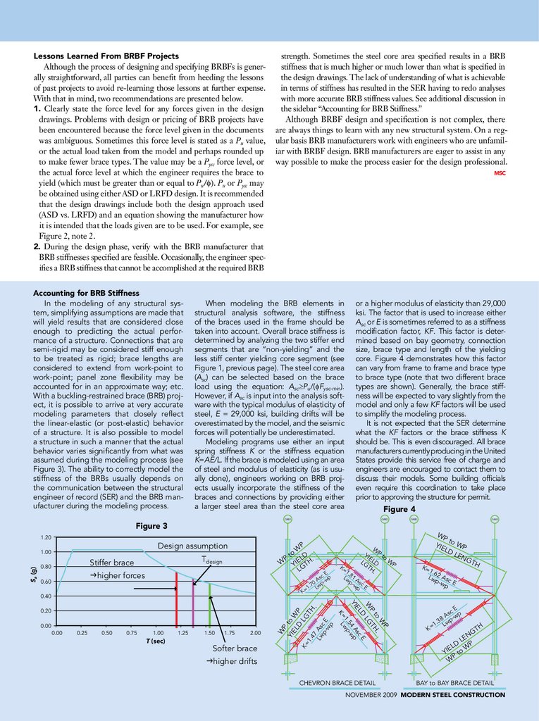
of a structure. It is also possible to model
a structure in such a manner that the actual
behavior varies significantly from what was
assumed during the modeling process (see
Figure 3). The ability to correctly model the
stiffness of the BRBs usually depends on
the communication between the structural
engineer of record (SER) and the BRB manufacturer during the modeling process.
strength. Sometimes the steel core area specified results in a BRB
stiffness that is much higher or much lower than what is specified in
the design drawings. The lack of understanding of what is achievable
in terms of stiffness has resulted in the SER having to redo analyses
with more accurate BRB stiffness values. See additional discussion in
the sidebar “Accounting for BRB Stiffness.”
Although BRBF design and specification is not complex, there
are always things to learn with any new structural system. On a regular basis BRB manufacturers work with engineers who are unfamiliar with BRBF design. BRB manufacturers are eager to assist in any
way possible to make the process easier for the design professional.
When modeling the BRB elements in
structural analysis software, the stiffness
of the braces used in the frame should be
taken into account. Overall brace stiffness is
determined by analyzing the two stiffer end
segments that are “non-yielding” and the
less stiff center yielding core segment (see
Figure 1, previous page). The steel core area
(Asc) can be selected based on the brace
load using the equation: Asc≥Pu/(φFysc-min).
However, if Asc is input into the analysis software with the typical modulus of elasticity of
steel, E = 29,000 ksi, building drifts will be
overestimated by the model, and the seismic
forces will potentially be underestimated.
Modeling programs use either an input
spring stiffness K or the stiffness equation
K=AE/L. If the brace is modeled using an area
of steel and modulus of elasticity (as is usually done), engineers working on BRB projects usually incorporate the stiffness of the
braces and connections by providing either
a larger steel area than the steel core area
or a higher modulus of elasticity than 29,000
ksi. The factor that is used to increase either
Asc or E is sometimes referred to as a stiffness
modification factor, KF. This factor is determined based on bay geometry, connection
size, brace type and length of the yielding
core. Figure 4 demonstrates how this factor
can vary from frame to frame and brace type
to brace type (note that two different brace
types are shown). Generally, the brace stiffness will be expected to vary slightly from the
model and only a few KF factors will be used
to simplify the modeling process.
It is not expected that the SER determine
what the KF factors or the brace stiffness K
should be. This is even discouraged. All brace
manufacturers currently producing in the United
States provide this service free of charge and
engineers are encouraged to contact them to
discuss their models. Some building officials
even require this coordination to take place
prior to approving the structure for permit.
Figure 4
GriD
Figure 3
GriD
GriD
GriD
1.20
Design assumption
Stiffer brace
P
higher forces
0.40
0.50
0.75
1.00
T (sec)
1.25
1.50
1.75
2.00
Softer brace
P
W
to H.
T
lG
0.25
higher drifts
CHevron brACe DeTAil
k=
WP
to
W
yie
lD P
len
GT
1.6
lw 2 Asc
p-w e
p
P
0.00
1.
lw 81 A
p- sc
wp e
W
0.00
k=
W
yi P to
e
W
lG lD
P
TH
.
D
ce
el
As p
yi
54 -w
1. wp
k= l
0.20
p- sc e
wp
0.60
ce
As -wp
70 wp
.
1 l
k=
lw
0.80
W
to lD
.
W yie TH
lG
Tdesign
W
P
yi to
el W
D P
lG
k=
TH
1.
47
.
A
Sa (g)
1.00
P
k
H
ce
As -wp
8
p
.3 w
=1 l
TH
nG
e
l
lD WP
yie to
P
W
bAy to bAy brACe DeTAil
november 2009 MODERN STEEL CONSTRUCTION