


 physics
 industry
Similar presentations:


")

Practical Look to Dynamic Stability
1.
PRACTICAL LOOKTO
DYNAMIC STABILITY
What means under “Dynamic
stability”
Two practical ways “how to do” table
for to build diagram of Dynamic
stability
Which data we can get from our
1
2.
Dynamic stabilitySometimes happens vessel floats it smooth water and then
unforeseen appears squally wind or big swell and vessel get a
dynamic inclination, may be for a short time , but more exceeding
then inclination which could appear during static action of same
moment.
Let’s imagine that our vessel is upright and then unpredictable to
she attached some moment under force of which vessel start heel
with acceleration so as on initial period other moment which try
to return vessel to initial position will be much slower.
After vessel reach certain position when heeling moment will be
equal to moment trying to return vessel to initial position (Righting
moment) and acceleration will be maximum, vessel continue to
heel, but already she’s acceleration will be much less . That
means that moment trying to return vessel to initial position
“Righting moment” getting more then “Heeling moment”.
At certain moment acceleration of vessel becomes “0”, heeling
angle reach its maximum (Angle of dynamic heel) and vessel
stuck in this position. After this vessel return to its initial position.
Under dynamic moment called “Heeling moment” we use maximum 2
attached to vessel moment which she can keep without collapse.
3.
Dynamic stabilityUnder dynamic stability means ability of vessel to
withstand dynamic impact of heeling moment.
The relative measure of dynamic stability is dynamic
stability arm.
Lets build a diagram looks like transverse static
stability, but on axis of ordinates Y we apply “Righting
moments” which we calculate with simple formula
Righting moment = GZ x Displacement
Please see next page.
We expect that due to some external force vessel heels
to 30 deg
Dynamical stability determined by area under the curve
of righting moments from “0” up to the heel concerned
3
(our case 30 deg) eg it is SUM of forces (righting
4.
Dynamic stabilityFor to build DYNAMIC STABILITY diagram we will
use formula
Righting moment = GZ x Displacement
Righting moments
8000
7000
6000
5000
4000
3000
2000
1000
0
10
20
30
40
50
60
70
80
Heel deg
4
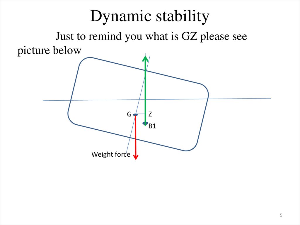
5.
Dynamic stabilityJust to remind you what is GZ please see
picture below
G
Z
B1
Weight force
5
6.
Dynamic stabilityIn practice usually used not diagram which we build before for dynamic
stability, but we build diagram of dynamic stability basing on diagram of
SUM of GZ for different ϴ
transverse
static
stability.
ϴ
GZ
(from static
transverse stability)
GZ dynamic
0
GZ 0
Ʃ=0
0
10
GZ 10
Ʃ10 = GZ10
0.0873 X Ʃ10
20
GZ 20
Ʃ20 = 2 X GZ10 + GZ20
0.0873 X Ʃ20
30
GZ 30
Ʃ30 = 2GZ10 + 2GZ20 + GZ30
0.0873 X Ʃ30
40
GZ 40
Ʃ40 = 2GZ10 + 2GZ20 + 2GZ30 +
GZ40
0.0873 X Ʃ40
50
GZ 50
Ʃ50 = 2GZ10 + 2GZ20 + 2GZ30 +
2GZ40 + GZ50
0.0873 X Ʃ50
60
GZ 60
Ʃ60 = 2GZ10 + 2GZ20 + 2GZ30 +
2GZ40 + 2GZ50 + GZ60
0.0873 X Ʃ60
70
GZ 70
Ʃ70 = 2GZ10 + 2GZ20 + 2GZ30 +
2GZ40 + 2GZ50 + 2GZ60 + GZ70
0.0873 X Ʃ70
80
GZ 80
Ʃ80 = 2GZ10 + 2GZ20 + 2GZ30 +
2GZ40 + 2GZ50 + 2GZ60 + 2GZ70 +
GZ80
0.0873 X Ʃ80
90
GZ 90
Ʃ90 = 2GZ10 + 2GZ20 + 2GZ30 +
2GZ40 + 2GZ50 + 2GZ60 + 2GZ70 +
2GZ80 + GZ90
0.0873 X Ʃ90
6
7.
Dynamic stabilityOther possible way for calculations
ϴ(with digits)
0
10
20
30
40
50
60
70
80
GZ static
0
0.16
0.28
0.48
0.47
0.3
0.21
0.1
-0.10
Ʃ
0
0.16
0.60
1.36
2.31
3.08
3.59
3.9
3.9
GZdin
=0.0872 x Ʃ
0
0.01
0.05
0.12
0.2
0.27
0.31
0.34
3.9
Check
Ʃ10= 0+0+0.16=0.16
0.01
Ʃ20 = 0.16+0.16+0.28= 0.6
GZdin10 = 0.16 x 0.0872 =
GZdin20 = 0.6 x 0.0872 =7
8.
Dynamic stabilityAfter completion of above table (one of shown
before for your choice) we build dynamic stability
Maximum lever GZ
GZdin
diagram.
point D
D
B
C
E
GZ max
allowable
A
ϴ of
max
heeling
ϴ dyn
ϴ
1 rad = 57.3 grad
8
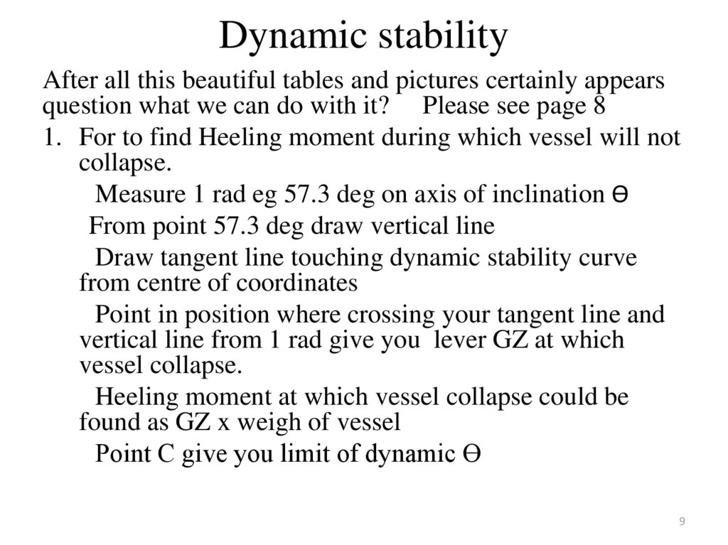
9.
Dynamic stabilityAfter all this beautiful tables and pictures certainly appears
question what we can do with it? Please see page 8
1. For to find Heeling moment during which vessel will not
collapse.
Measure 1 rad eg 57.3 deg on axis of inclination ϴ
From point 57.3 deg draw vertical line
Draw tangent line touching dynamic stability curve
from centre of coordinates
Point in position where crossing your tangent line and
vertical line from 1 rad give you lever GZ at which
vessel collapse.
Heeling moment at which vessel collapse could be
found as GZ x weigh of vessel
Point C give you limit of dynamic ϴ
9
10.
Dynamic stabilityWhen we build diagram of dynamic stability we expect
dynamic heeling moment as permanent for different angles of
inclination then it’s work
Will be in linear dependency from inclination and could be
presented as a strait line passing through center of
coordinates.
For to build it we install vertical line from point 1 rad=57,3
deg and mark on it given GZ (point E)
Strait line passing through center of coordinates and point E
will be graph of work of Heeling moment related to force of
weight of vessel.
This strait line cross diagram of dynamic stability in 2 points
“A” and “B”.
Perpendicular from “A” to axis ϴ give you angle ϴdin in
which work of Heeling moment and Upright moment will be
equal.
10
Point “B” has no practical use.
11.
After wordHere I am not talk about how to use Transverse
static stability diagram for to solve questions of
Dynamic stability.
Everything step by step and preferably attached
to practice then will be more easy to understand
“for what?”
I’ll be thankful to professionals who give me
some feedback with own opinion about my
articles.
You can use my e-mail windy2000@mail.ru
Or say something below my videos on You tube
11