


 mathematics
 physics
Similar presentations:


")


Construction of the final diagrams of internal forces in a statically indeterminate system by the displacement. Lecture 14
1. Lecture 14. Construction of the final diagrams of internal forces in a statically indeterminate system by the displacement
methodThe principle of independence of the action of forces
(Principle of superposition)
The result from the action of a combination of forces is
equal to the sum of the results from each force separately.
This principle is valid for small loads and small
deformations of an elastic system.
On the basis of this principle, the final forces in a given
statically indeterminate system are decomposed into the
load forces and the reactions of the discarded bonds
separately.
2.
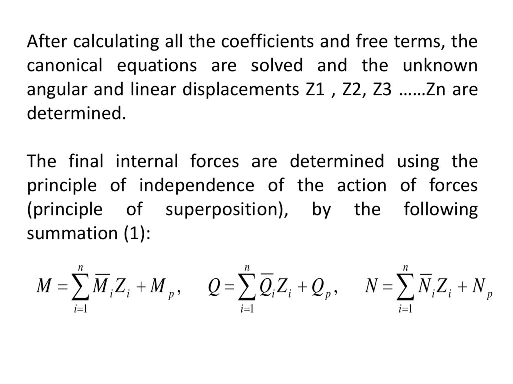
After calculating all the coefficients and free terms, thecanonical equations are solved and the unknown
angular and linear displacements Z1 , Z2, Z3 ……Zn are
determined.
The final internal forces are determined using the
principle of independence of the action of forces
(principle of superposition), by the following
summation (1):
n
M M i Zi M p ,
i 1
n
Q Qi Z i Q p ,
i 1
n
N Ni Zi N p
i 1
3.
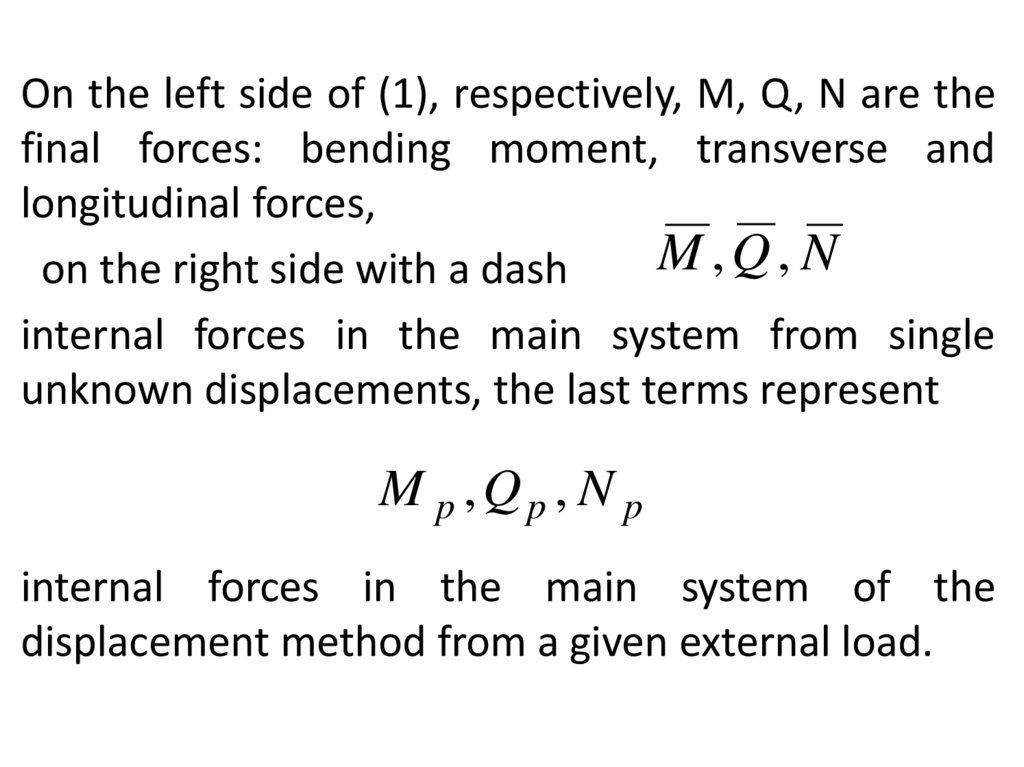
On the left side of (1), respectively, M, Q, N are thefinal forces: bending moment, transverse and
longitudinal forces,
M ,Q, N
on the right side with a dash
internal forces in the main system from single
unknown displacements, the last terms represent
M p ,Qp , N p
internal forces in the main system of the
displacement method from a given external load.
4. Static and kinematic checks of M, Q, N diagrams
1. Static checksF 0, F 0
x
y
2. Kinematic checks (superscript 0 means that unit
diagrams are built in the main system of the force
method)
5. The use of symmetry. A symmetric system refers to a system in which there is an axis of symmetry, i.e. with respect to which
there is a mirror image. In the presented system, the degree ofkinematic freedom is equal to 4. Let us decompose the
constraints in the main system of the displacement method into
symmetrical and inversely symmetrical, i.e. We use the grouping
of unknowns.
Z1 , Z 3, Z 4 -reversely symmetric unknowns;
Z2 - symmetrical angular displacement
6. Canonical equations of the displacement method
The canonical equations fall into two systems: The firstsystem refers to symmetric unknowns ( Z1 , Z 3 , Z 4 ) ;
the second - to the inversely symmetrical unknown .
Reactions in symmetric bonds from unit
Z 2 displacements
of inversely symmetrical bonds are equal to zero and
vice versa.
Z1r11 Z3r13 Z 4 r14 R1p 0
Z1r31 Z3r33 Z 4 r34 R 3p 0
Z1r41 Z343 Z 4 r44 R 4p 0
Z 2 r22 R1p 0
7. Formulas for final forces in a symmetrical system
After calculating all the coefficients and free terms, thecanonical equations are solved and the unknown
angular and linear displacements Z1, Z2, Z3, Z4 are
determined.
The final internal forces are determined using the
principle of independence of the action of forces
(principle of superposition), by the following summation
(1):
4
M M i Zi M p ,
i 1
4
Q Qi Zi Q p ,
i 1
4
N N i Zi N p
i 1
8. MD algorithm
1. From a given statically indeterminate system, they pass to themain system of the displacement method - kinematically
determinable, which is obtained from the given one by
introducing constraints that prevent linear and angular
displacements of the system nodes.
2. The unknowns are the angular and linear displacements in
superimposed constraints.
3. Static equations are compiled that negate reactions in
superimposed constraints (Canonical equations).
4. Using the tabular values of the reactions, unit and load
diagrams are built, from which the coefficients and free terms of
the canonical equations are determined.
4. By solving these equations and determining the unknown
displacements in superimposed constraints, plots of internal
forces are built using the principle of independence of forces.
9. Matrix form of the displacement method. Stiffness matrix.
Lr Z R p 0• Lr
- is a matrix consisting of unit coefficients,
Z
- a vector whose components are unknown displacements in
the introduced links,
• Rp
is a vector whose components are the free terms of the
canonical equations.
10. Matrix Actions
r11 r12 r13Lr r21 r22 r23 ,
r r r
31 32 33
Lr L1 BL1 ,
1 p
Rp 2p ,
3p
C L1 B,
X1
Z X2
X
3
0
R p CL p ,
11. Determination of the coefficients and free terms of the canonical equations of the displacement method
M i M k dxrik
,
EI
Rip
0
M i M p dx
EI
•i,k = 1,2,3……..n
M 0p
represents a diagram of bending moments in any statically
determinate system, obtained from a given one, from an external
influence p.
12.
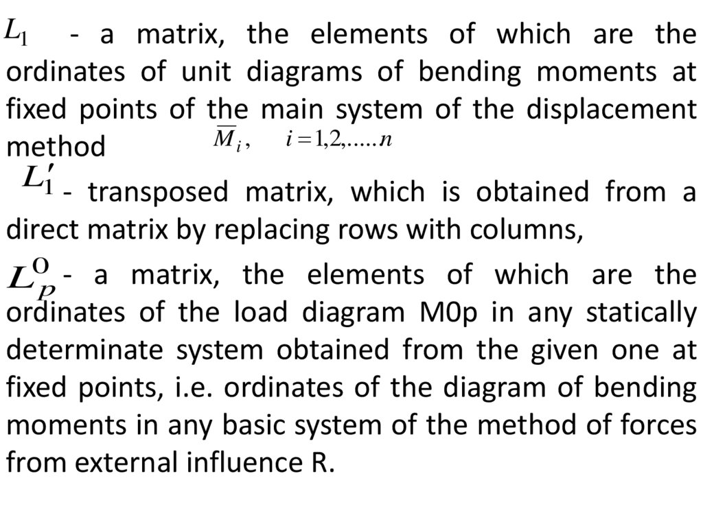
L1 - a matrix, the elements of which are theordinates of unit diagrams of bending moments at
fixed points of the main system of the displacement
M i , i 1,2,......n
method
L1 - transposed matrix, which is obtained from a
direct matrix by replacing rows with columns,
L0p - a matrix, the elements of which are the
ordinates of the load diagram М0р in any statically
determinate system obtained from the given one at
fixed points, i.e. ordinates of the diagram of bending
moments in any basic system of the method of forces
from external influence R.
13. Compliance matrix B
B10
0
0
B
0
.
.
0
0
B2
0
0
0
.
.
0
0
0
B3
0
0
.
.
0
0
0
0
.
0
.
.
.
.
.
.
.
.
.
.
.
.
.
.
.
.
.
.
.
. 0
. 0
. 0
. 0
.
. 0
. .
. .
. B s
14. Construction of the final diagrams of internal forces
1Z Lr R
M L1 Z L p ,
dM
Q
K M
dx
1
K
L
1
L
15. Matrix K
1L1
0
K
.
.
,
1
L1
0
0
.
.
1 1
L2 L2
.
.
.
.
,
,
0
,
.
.
.
.
.
.
.
.
.
.
.
.
.
.
.
.
.
.
.
.
.
.
.
.
,
,
,
,
,
,
.
0
.
.
.
.
1 1
Ls Ls
.
0
16. Final diagrams of internal forces
nM M i Zi M p ,
i 1
n
Q Qi Z i Q p ,
i 1
n
N Ni Zi N p
i 1
17. Static and kinematic checks of M, Q, N diagrams
• Static checksF 0, F 0
x
y
• Kinematic checks
M i Mdx
0
EI
M s Mdx
EI 0,
i 1,2,...n
M s M 1 M 2 ... M n