


 electronics
 industry
Similar presentations:


 & Compressor Dehydrator")

SKIF injector complex
1.
SKIF injector complexZhuravlev Andrey
2.
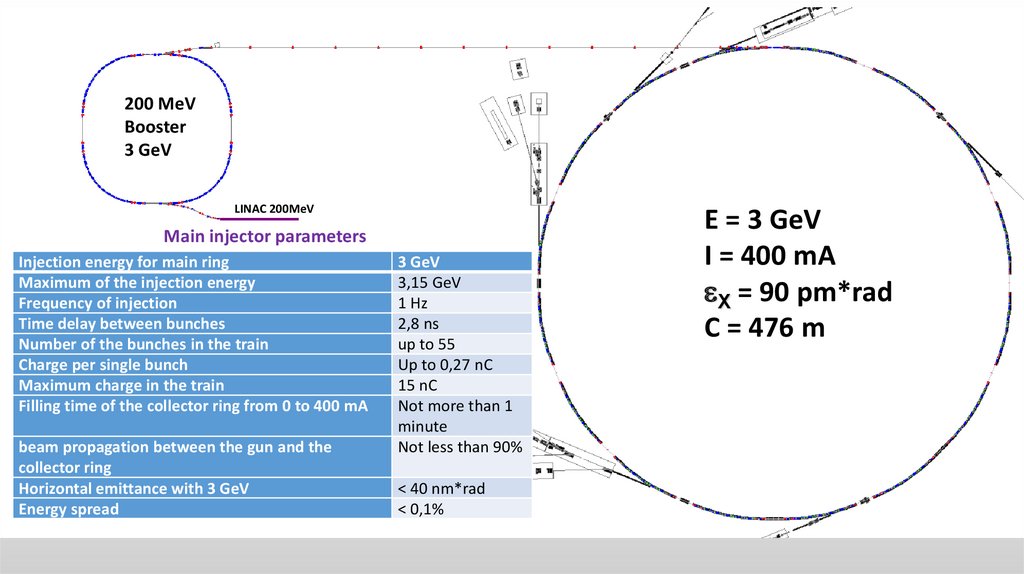
200 MeVBooster
3 GeV
LINAC 200MeV
Main injector parameters
Injection energy for main ring
Maximum of the injection energy
Frequency of injection
Time delay between bunches
Number of the bunches in the train
Charge per single bunch
Maximum charge in the train
Filling time of the collector ring from 0 to 400 mA
beam propagation between the gun and the
collector ring
Horizontal emittance with 3 GeV
Energy spread
3 GeV
3,15 GeV
1 Hz
2,8 ns
up to 55
Up to 0,27 nC
15 nC
Not more than 1
minute
Not less than 90%
< 40 nm*rad
< 0,1%
E = 3 GeV
I = 400 mA
X = 90 pm*rad
C = 476 m
3.
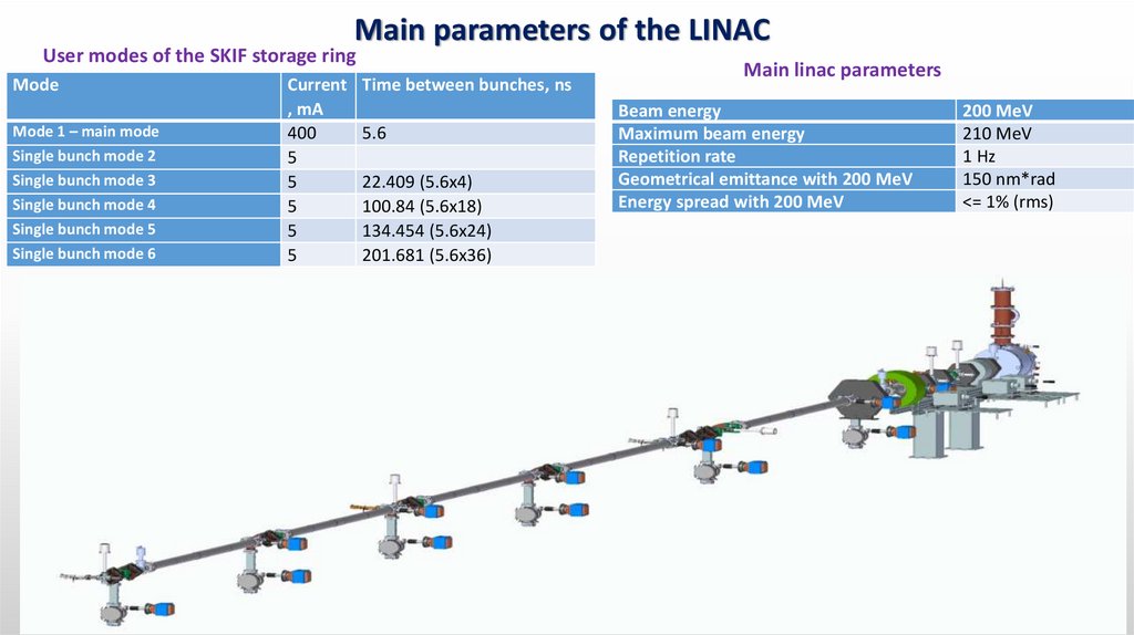
Main parameters of the LINACUser modes of the SKIF storage ring
Mode
Mode 1 – main mode
Single bunch mode 2
Single bunch mode 3
Single bunch mode 4
Single bunch mode 5
Single bunch mode 6
Current
, mA
400
5
5
5
5
5
Time between bunches, ns
5.6
22.409 (5.6х4)
100.84 (5.6х18)
134.454 (5.6x24)
201.681 (5.6x36)
Main linac parameters
Beam energy
Maximum beam energy
Repetition rate
Geometrical emittance with 200 MeV
Energy spread with 200 MeV
200 MeV
210 MeV
1 Hz
150 nm*rad
<= 1% (rms)
4.
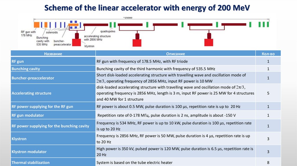
Scheme of the linear accelerator with energy of 200 MeVНазвание
Описание
Кол-во
RF gun
RF gun with frequency of 178.5 MHz, with RF triode
1
Bunching cavity
Bunching cavity of the third harmonic with frequency of 535.5 MHz
Short disk-loaded accelerating structure with travelling wave and oscillation mode of
, operating frequency of 2856 MHz, input RF power is 10 MW
disk-loaded accelerating structure with travelling wave and oscillation mode of ,
operating frequency is 2856 MHz, length is 3 m, input RF power is 25 MW for 4 structures
and 40 MW for 1 structure
1
RF power supplying for the RF gun
RF power is about 0.5 MW, pulse duration is 100 µs, repetition rate is up to 20 Hz
1
RF gun modulator
Repetition rate of 0-178 МГц, pulse duration is 2 ns, amplitude is about -150 V
1
RF power supplying for the bunching cavity
Frequency is 534 MHz, RF power is up to 10 kW, pulse duration is 100 µs, repetition rate
is up to 20 Hz
1
Klystron
Frequency is 2856 MHz, RF power is 50 MW, pulse duration is 4 µs, repetition rate is up
to 20 Hz
3
Klystron modulator
High power is 350 kV, pulsed power is 120 MW, pulse duration is 6.5 µs, repetition rate is
20 Hz
3
Thermal stabilization
System is based on the tube electric heater
8
Buncher-preaccelerator
Accelerating structure
1
5
5.
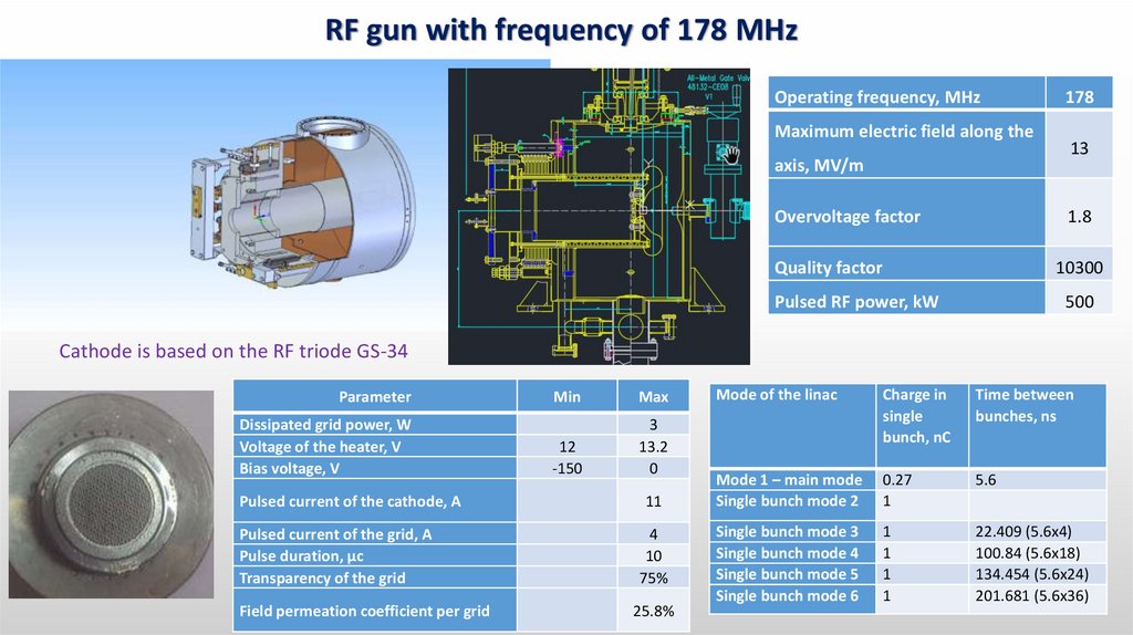
RF gun with frequency of 178 MHzOperating frequency, MHz
Maximum electric field along the
axis, MV/m
Overvoltage factor
178
13
1.8
Quality factor
10300
Pulsed RF power, kW
500
Cathode is based on the RF triode GS-34
Parameter
Dissipated grid power, W
Voltage of the heater, V
Bias voltage, V
Pulsed current of the cathode, А
Pulsed current of the grid, А
Pulse duration, μс
Transparency of the grid
Field permeation coefficient per grid
Min
Max
12
-150
3
13.2
0
11
4
10
75%
25.8%
Mode of the linac
Charge in
single
bunch, nC
Time between
bunches, ns
Mode 1 – main mode
Single bunch mode 2
0.27
1
5.6
Single bunch mode 3
Single bunch mode 4
Single bunch mode 5
Single bunch mode 6
1
1
1
1
22.409 (5.6х4)
100.84 (5.6х18)
134.454 (5.6x24)
201.681 (5.6x36)
6.
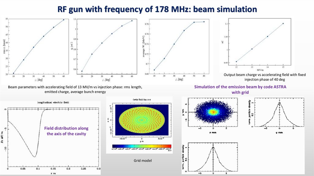
RF gun with frequency of 178 MHz: beam simulationOutput beam charge vs accelerating field with fixed
injection phase of 40 deg
Beam parameters with accelerating field of 13 MV/m vs injection phase: rms length,
emitted charge, average bunch energy
Field distribution along
the axis of the cavity
Grid model
Simulation of the emission beam by code ASTRA
with grid
7.
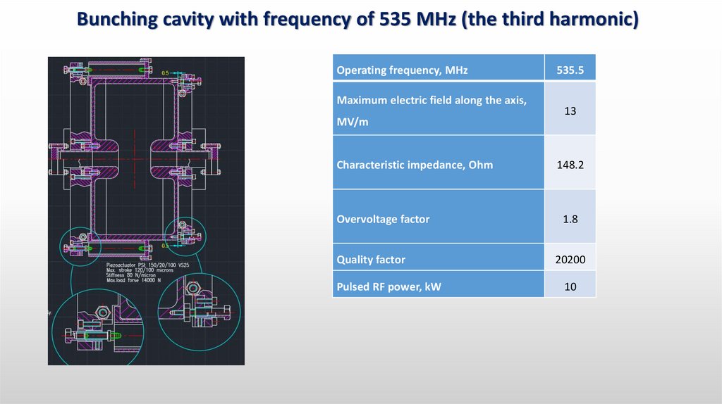
Bunching cavity with frequency of 535 MHz (the third harmonic)Operating frequency, MHz
Maximum electric field along the axis,
MV/m
Characteristic impedance, Ohm
Overvoltage factor
Quality factor
Pulsed RF power, kW
535.5
13
148.2
1.8
20200
10
8.
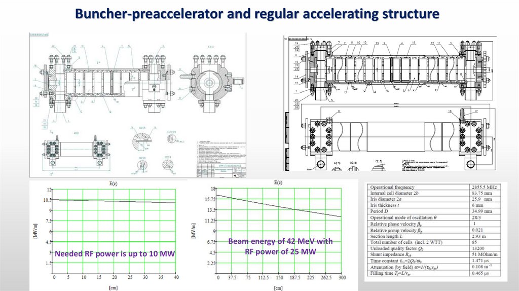
Buncher-preaccelerator and regular accelerating structureNeeded RF power is up to 10 MW
Beam energy of 42 MeV with
RF power of 25 MW
9.
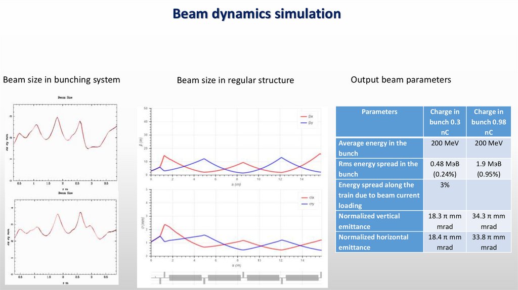
Beam dynamics simulationBeam size in bunching system
Beam size in regular structure
Output beam parameters
Parameters
Average energy in the
bunch
Rms energy spread in the
bunch
Energy spread along the
train due to beam current
loading
Normalized vertical
emittance
Normalized horizontal
emittance
Charge in
bunch 0.3
nC
200 MeV
Charge in
bunch 0.98
nC
200 MeV
0.48 МэВ
(0.24%)
3%
1.9 МэВ
(0.95%)
18.3 π mm
mrad
18.4 π mm
mrad
34.3 π mm
mrad
33.8 π mm
mrad
10.
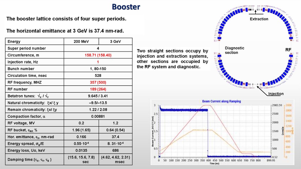
BoosterThe booster lattice consists of four super periods.
Extraction
The horizontal emittance at 3 GeV is 37.4 nm-rad.
Energy
200 MeV
3 GeV
4
Super period number
Circumference, m
158.71 (158.40)
Injection rate, Hz
1
Bunch number
1, 80-150
Circulation time, nsec
357 (500)
RF number
189 (264)
Betatron tunes: X / Y
9.645 / 3.41
Natural chromaticity: x/ y
–9.5/–13.5
Remain chromaticity: x/ y
1.22 / 2.08
Compaction factor,
0.00881
1.2
1.96 (1.65)
0.64 (0.54)
0.166
37.4
Energy spread, σE/E
0.55·10-4
8. 31·10-4
Energy loss, Uо, keV
0.0135
686
(15.6, 15.6, 7.8)
sec
(4.62, 4.62, 2.31)
msec
Hor. emittance, X, nm-rad
Damping time:( X, Y, S )
RF
Injection
0.2
RF bucket, RF, %
Diagnostic
section
528
RF frequency, MHZ
RF voltage, MV
Two straight sections occupy by
injection and extraction systems,
other sections are occupied by
the RF system and diagnostic.
11. Booster lattice
Super period consists of 5 cells with two modified cells at the edges to suppress dispersion.8 defocusing dipoles (BD) with rotation angle 8.39 ,
7 focusing dipoles (BF) with rotation angle3.27 ,
6 quadrupole lenses,
4 sextupole lenses (2хSD, 2хSF).
Betatron frequency:
νx = 9.645
νy = 3.41
To compensate chromatism, a sextupole component is embedded in dipole magnets.
11
12. Main parameters of the booster magnets
Booster magnetsMain parameters
Type
ofBFthe
BD
Dipole magnets
Number Length, m , deg
booster
magnets
28
1.24
3.2673
32
1.3
8.391
K1,1/m2
0.82
-0.5551
K2,1/m3
3.6
-4.3
Quadrupole lenses
QF
QD
QG
8
8
8
SF
SD
8
8
0.3
2.0425
0.3
-1.5014
0.3
1.3361
Sextupole lenses
0.12
0.12
40
-40
13. LINAC to Booster transfer line
2 dipoles with rotation angle 230 mrad,2 dipoles with rotation angle 163.2 mrad,
10 quadrupole lenses,
4 dipole correctors
Diagnostic system:
6 BPMs
6 fluorescent screens
2 current transformers for current
measure
14.
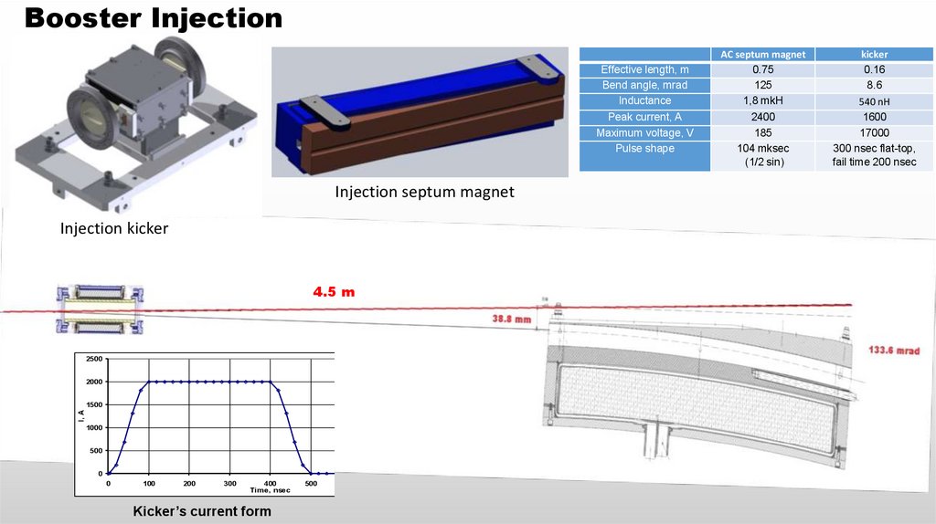
Booster InjectionEffective length, m
Bend angle, mrad
Inductance
Peak current, A
Maximum voltage, V
Pulse shape
Injection septum magnet
Injection kicker
4.5 m
2500
2000
I, A
1500
1000
500
0
0
100
200
300
400
Time, nsec
Kicker’s current form
500
600
700
800
AC septum magnet
0.75
125
1,8 mkH
2400
185
104 mksec
(1/2 sin)
kicker
0.16
8.6
540 nH
1600
17000
300 nsec flat-top,
fail time 200 nsec
15.
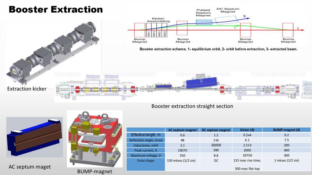
Booster ExtractionBooster extraction scheme. 1- equilibrium orbit, 2- orbit before extraction, 3- extracted beam.
Extraction kicker
Booster extraction straight section
Effective length, m
Deflection angle, mrad
Inductance, mkH
Peak current, A
Maximum voltage, V
Pulse shape
AC septum maget
BUMP-magnet
AC septum magnet
0.6
48
2.1
10070
550
150 mksec (1/2 sin)
DC septum magnet
1.2
116
20000
380
8.8
DC
Kicker (4)
0.2х4
6.1
2.513
2000
19750
215 nsec rise time,
300 nsec flat-top
BUMP-magnet (4)
0.2
7.5
200
400
300
1 mksec (1/2 sin)
16.
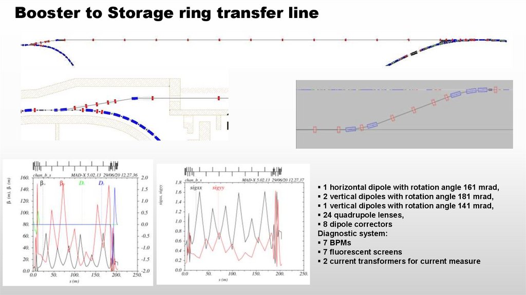
Booster to Storage ring transfer line1 horizontal dipole with rotation angle 161 mrad,
2 vertical dipoles with rotation angle 181 mrad,
1 vertical dipoles with rotation angle 141 mrad,
24 quadrupole lenses,
8 dipole correctors
Diagnostic system:
7 BPMs
7 fluorescent screens
2 current transformers for current measure
17.
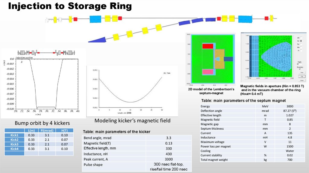
Injection to Storage Ring2D model of the Lembertson’s
septum-magnet
Magnetic fields in aperture (Hin = 0.853 T)
and in the vacuum chamber of the ring
(Нout≈ 0.4 mT)
Table: main parameters of the septum magnet
Bump orbit by 4 kickers
Kick1
Kick2
Kick3
Kick4
L(m)
0.33
0.33
0.33
0.33
Fi(mrad)
3.1
2.1
2.1
3.1
Н(Т)
0.10
0.07
0.07
0.10
Modeling kicker’s magnetic field
Table: main parameters of the kicker
Bend angle, mrad
Magnetic field(T)
Effective length, mm
Inductance, nH
Peak current, A
Pulse shape
3.3
0.13
330
430
3300
300 nsec flat-top,
rise/fail time 200 nsec
Energy
Deflection angle
Effective length
Magnetic field
Magnetic gap
Septum thickness
Current
Inductance
Maximum voltage
Power loss per magnet
Cooling
Current stability
Total magnet weight
MeV
mrad
m
Т
mm
mm
А
mH
V
W
%
kg
3000
87.27 (5⁰)
1.027
0.85
8
2
135
4.8
11
1500
Water
0.02
700
18. Estimates of injection
1. The usual mode is injection train of bunches up to300 nsec long containing of 55 bunches with the total
charge 15 nC (9.5 mA of SR).
2. Initial obtaining current from 0 to 400 mA in 45 sec.
3. For maintaining a working current of 5 %, need
adding every 3 minutes, with beam lifetime 5 hours.
4. For exotic modes, single-bunch injection with a
charge up to 1 nC are available.