


 electronics
Similar presentations:


 - Technical Highlights")


")


TPMS Introduction (v.2)
1.
TPMS IntroductionGWM-PPT V2010.1
2.
TPMS TypeTPMS
Pressure-Sensor Based TPMS shorten for:PSB TPMS, or
directness type TPMS ,namely this system monitors tyre
pressure by pressure sensor mounted inner tyre thus to
display information or warning.
GWM-PPT V2010.1
2
3.
Working principleWhen vehicle speed exceeds 20Km/h,type
pressure sensor begins to work. When vehicle stops
for 10 minutes, sensor will entre “sleep”mode for
power saving.
GWM-PPT V2010.1
3
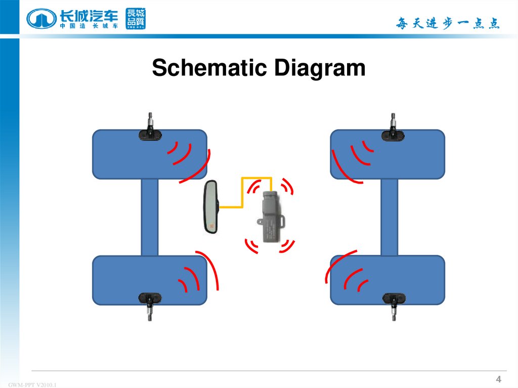
4.
Schematic DiagramGWM-PPT V2010.1
4
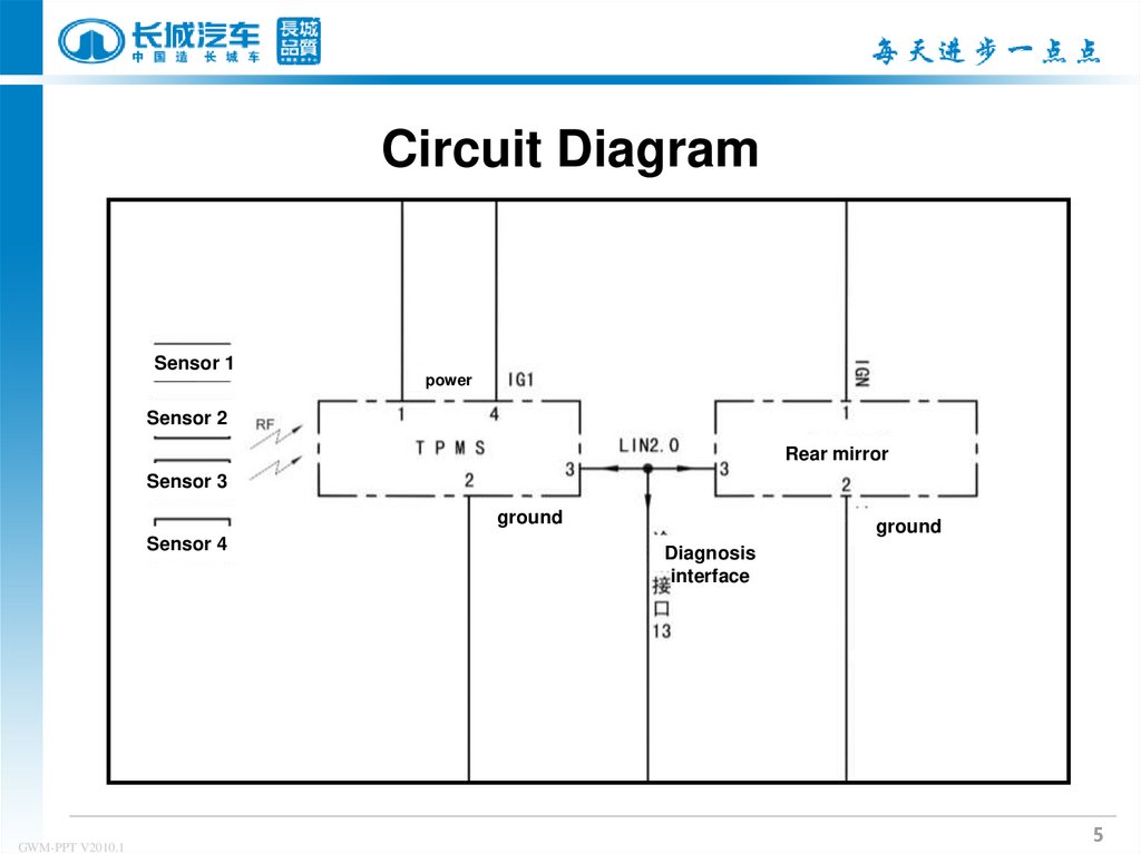
5.
Circuit DiagramSensor 1
power
Sensor 2
Rear mirror
Sensor 3
ground
Sensor 4
GWM-PPT V2010.1
ground
Diagnosis
interface
5
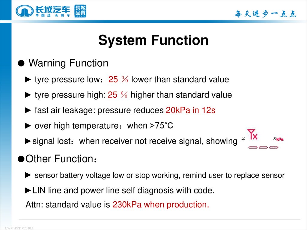
6.
System Function● Warning Function
► tyre pressure low 25 lower than standard value
► tyre pressure high: 25 higher than standard value
► fast air leakage: pressure reduces 20kPa in 12s
► over high temperature when >75˚C
►signal lost when receiver not receive signal, showing“
”
●Other Function
► sensor battery voltage low or stop working, remind user to replace sensor
►LIN line and power line self diagnosis with code.
Attn: standard value is 230kPa when production.
GWM-PPT V2010.1
7.
System ComponentPressure receiver
Tyre pressure sensor
Rear mirror
GWM-PPT V2010.1
7
8. Tyre Pressure sensor
The sensor is mounted inside each wheel to monitor tyre pressure andtemperature, then send signal to tyre pressure receiver through RF
air valve bonnet
air valve nut
Rubber washer
bolt
Tyre pressure monitor emitter
GWM-PPT V2010.1
8
9. Location: don’t forget tyre balance operationg before mounting
GWM-PPT V2010.19
10. Sensor Mount
① screw down nut, then mount air valve nozzle through wheel hub hole② screw up nut, then tighten with torque 3.8N.m ±0.3 by sleeve
GWM-PPT V2010.1
10
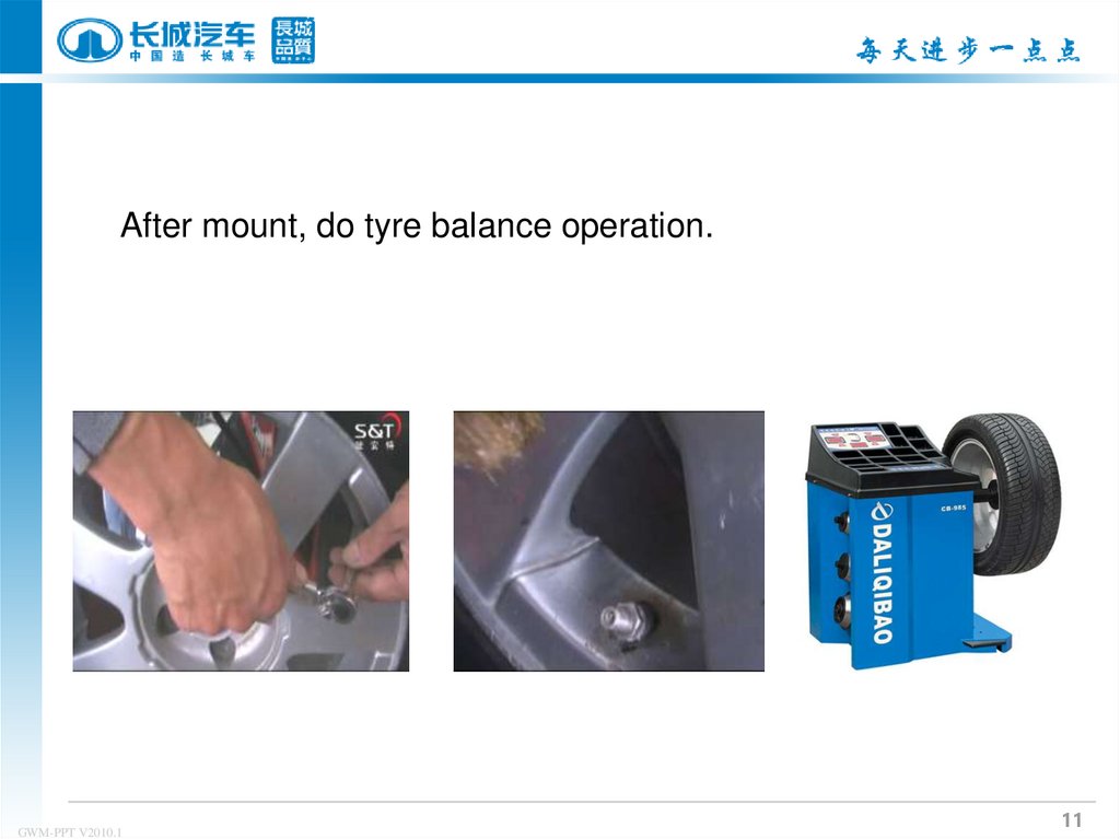
11.
After mount, do tyre balance operation.GWM-PPT V2010.1
11
12. Receiver Location
receiverGWM-PPT V2010.1
12
13.
TPMS MaintenanceⅠ. TPMS Initialization Operation Guide
Ⅱ. Replace tyre pressure sensor
Ⅲ. Tyre rotation
Ⅳ. Lin bus self-diagnosis function
GWM-PPT V2010.1
13
14. TPMS Program Tool
BMG TPMS Program ToolMODEL:3641130-K80
INPUT:DC 9V
434MHz
SN:CHADXXXXXXXXX
Laser
DC-9V
GWM-PPT V2010.1
14
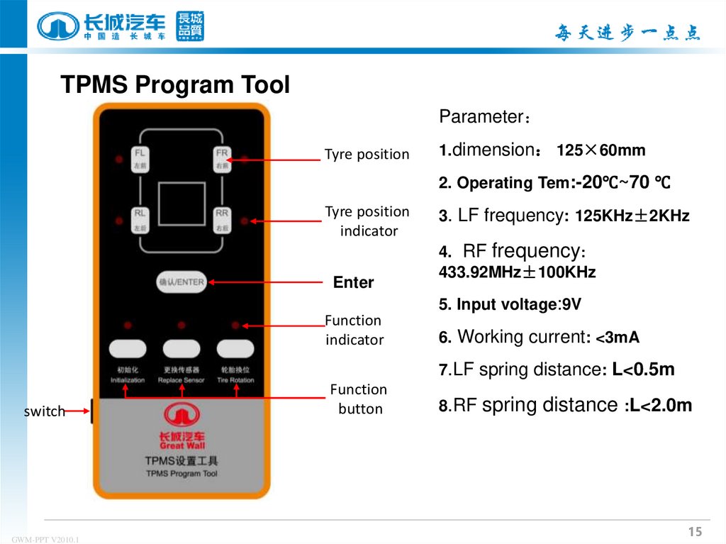
15.
TPMS Program ToolParameter
Tyre position
1.dimension 125×60mm
2. Operating Tem:-20℃~70 ℃
Tyre position
indicator
Enter
Function
indicator
3. LF frequency: 125KHz±2KHz
4. RF frequency:
433.92MHz±100KHz
5. Input voltage:9V
6. Working current: <3mA
7.LF spring distance: L<0.5m
switch
GWM-PPT V2010.1
Function
button
8.RF
spring distance :L<2.0m
15
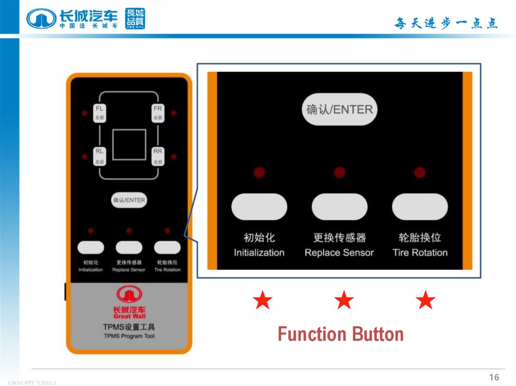
16.
★★
★
Function Button
GWM-PPT V2010.1
16
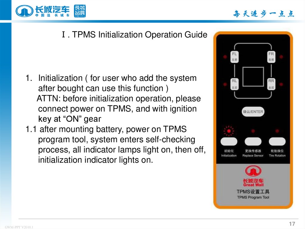
17.
Ⅰ. TPMS Initialization Operation Guide1. Initialization ( for user who add the system
after bought can use this function )
ATTN: before initialization operation, please
connect power on TPMS, and with ignition
key at “ON” gear
1.1 after mounting battery, power on TPMS
program tool, system enters self-checking
process, all indicator lamps light on, then off,
initialization indicator lights on.
GWM-PPT V2010.1
17
18.
1.2 put TPMS program tool close to tyre valvenib within 50 cm to set sensor to be registered,
press down corresponding tyre position button
on program tool like “FL”, “FR”, then tyre
position lamp will flash which means it’s waiting
for signal from sensor as showed by right figure.
After register succeeds, tyre position lamp will
keep on; TPMS program tool will cancel spring
if not receiving sensor signal in 10s.
GWM-PPT V2010.1
18
19.
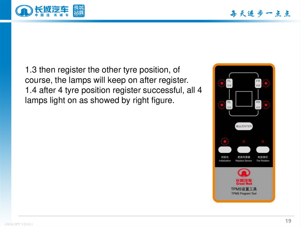
1.3 then register the other tyre position, ofcourse, the lamps will keep on after register.
1.4 after 4 tyre position register successful, all 4
lamps light on as showed by right figure.
GWM-PPT V2010.1
19
20.
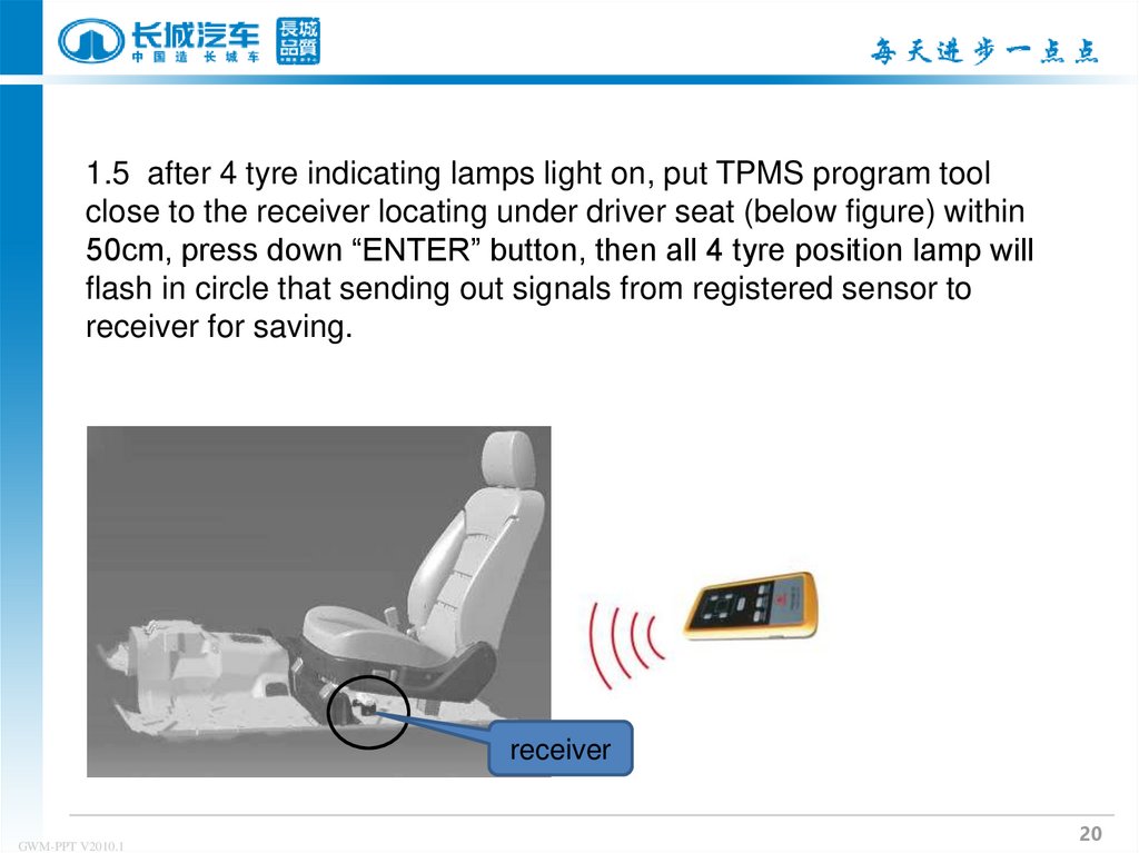
1.5 after 4 tyre indicating lamps light on, put TPMS program toolclose to the receiver locating under driver seat (below figure) within
50cm, press down “ENTER” button, then all 4 tyre position lamp will
flash in circle that sending out signals from registered sensor to
receiver for saving.
receiver
GWM-PPT V2010.1
20
21. Receiver
GWM-PPT V2010.122.
1.6 then there will be “SET” displayed in rear mirror, whichmeans initialization successful as showed by below
GWM-PPT V2010.1
22
23.
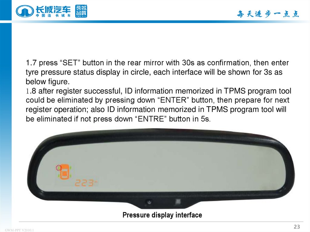
1.7 press “SET” button in the rear mirror with 30s as confirmation, then entertyre pressure status display in circle, each interface will be shown for 3s as
below figure.
1.8 after register successful, ID information memorized in TPMS program tool
could be eliminated by pressing down “ENTER” button, then prepare for next
register operation; also ID information memorized in TPMS program tool will
be eliminated if not press down “ENTRE” button in 5s.
Pressure display interface
GWM-PPT V2010.1
23
24.
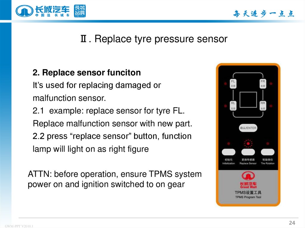
Ⅱ. Replace tyre pressure sensor2. Replace sensor funciton
It’s used for replacing damaged or
malfunction sensor.
2.1 example: replace sensor for tyre FL.
Replace malfunction sensor with new part.
2.2 press “replace sensor” button, function
lamp will light on as right figure
ATTN: before operation, ensure TPMS system
power on and ignition switched to on gear
GWM-PPT V2010.1
24
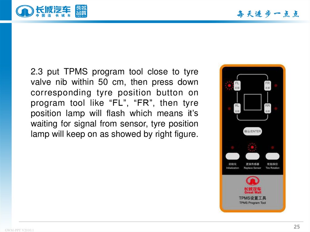
25.
2.3 put TPMS program tool close to tyrevalve nib within 50 cm, then press down
corresponding tyre position button on
program tool like “FL”, “FR”, then tyre
position lamp will flash which means it’s
waiting for signal from sensor, tyre position
lamp will keep on as showed by right figure.
GWM-PPT V2010.1
25
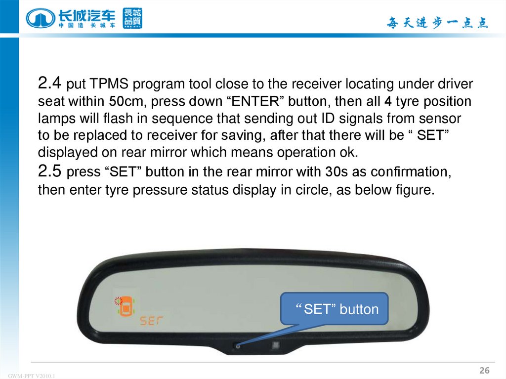
26.
2.4 put TPMS program tool close to the receiver locating under driverseat within 50cm, press down “ENTER” button, then all 4 tyre position
lamps will flash in sequence that sending out ID signals from sensor
to be replaced to receiver for saving, after that there will be “ SET”
displayed on rear mirror which means operation ok.
2.5 press “SET” button in the rear mirror with 30s as confirmation,
then enter tyre pressure status display in circle, as below figure.
“SET” button
GWM-PPT V2010.1
26
27.
Ⅲ. Tyre rotation3. Tyre rotation
there is no need to remove tyre pressure mounted inside tyre when
operating,only with TPMS program tool to adjust and reset orignal
emitter position that system could work normally.
GWM-PPT V2010.1
27
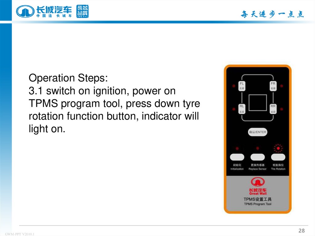
28.
Operation Steps:3.1 switch on ignition, power on
TPMS program tool, press down tyre
rotation function button, indicator will
light on.
GWM-PPT V2010.1
28
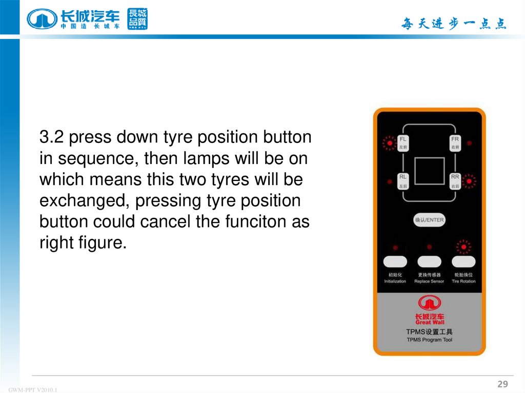
29.
3.2 press down tyre position buttonin sequence, then lamps will be on
which means this two tyres will be
exchanged, pressing tyre position
button could cancel the funciton as
right figure.
GWM-PPT V2010.1
29
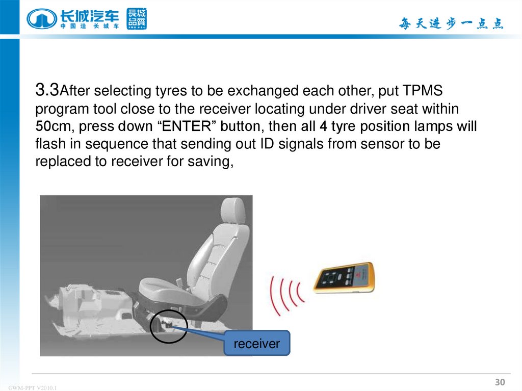
30.
3.3After selecting tyres to be exchanged each other, put TPMSprogram tool close to the receiver locating under driver seat within
50cm, press down “ENTER” button, then all 4 tyre position lamps will
flash in sequence that sending out ID signals from sensor to be
replaced to receiver for saving,
receiver
GWM-PPT V2010.1
30
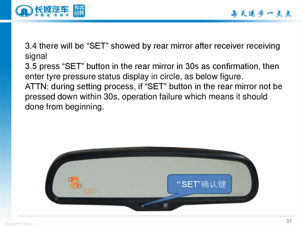
31.
3.4 there will be “SET” showed by rear mirror after receiver receivingsignal
3.5 press “SET” button in the rear mirror in 30s as confirmation, then
enter tyre pressure status display in circle, as below figure.
ATTN: during setting process, if “SET” button in the rear mirror not be
pressed down within 30s, operation failure which means it should
done from beginning.
“SET”确认键
GWM-PPT V2010.1
31
32.
Ⅳ. Lin bus self-diagnosis functionin case when
receiver and Lin
line or IGN power
line malfunction,
rear mirror will entre
into self diagnosis
function
All 4 tyre indicators show red color and flash for 5s
0.5S off, 0.5S on , buzzer warns 5 times
sound 0.5S silence 0.5S tyre pressure warning
sign ”
” and malfunction code will come on.
GWM-PPT V2010.1
32
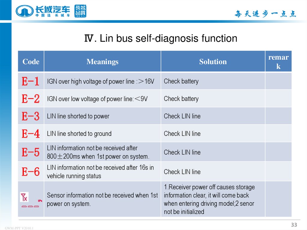
33.
Ⅳ. Lin bus self-diagnosis functionCode
Meanings
Solution
E-1
E-2
E-3
E-4
IGN over high voltage of power line : 16V
Check battery
IGN over low voltage of power line: 9V
Check battery
LIN line shorted to power
Check LIN line
LIN line shorted to ground
Check LIN line
E-5
LIN information not be received after
800±200ms when 1st power on system.
Check LIN line
E-6
LIN information not be received after 16s in
vehicle running status
Check LIN line
remar
k
1.Receiver power off causes storage
Sensor information not be received when 1st information clear, it will come back
when entering driving model;2 senor
power on system.
not be initialized
GWM-PPT V2010.1
33