


 electronics
Similar presentations:


Apparatus of installations with fluidized layer of pulverized catalyst
1. Apparatus of installations with fluidized layer of pulverized catalyst
Al-Farabi Kazakh national universityDepartment of physical chemistry,catalysis and petrochemistry
Apparatus of installations with fluidized layer
of pulverized catalyst
Performed by: Abdrassilova A.K.
Abik N.A.
Kurmangaliyeva A.B.
Otynshiyev Y.B.
Checked by Pavlenko V.V.
Almaty, 2019
2. Plan
Introduction;Main features of the process;
Conclusion;
3.
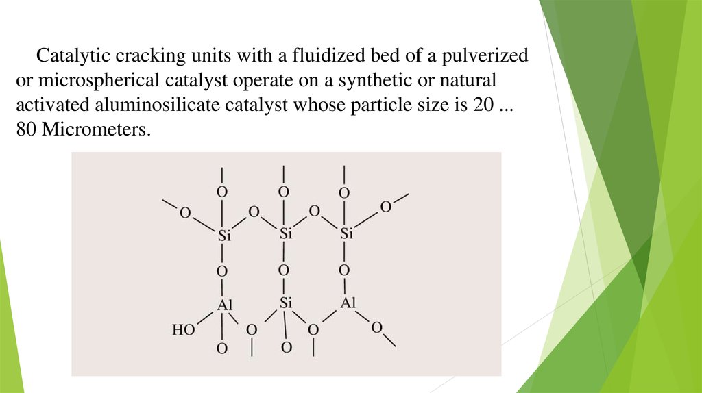
Catalytic cracking units with a fluidized bed of a pulverizedor microspherical catalyst operate on a synthetic or natural
activated aluminosilicate catalyst whose particle size is 20 ...
80 Micrometers.
4.
Main features of the processThe advantages of this type of cracking compared to cracking,
which uses a ball catalyst, are:
-
possibility of simple regulation within wide limits of degree
of transformation of raw materials and circulation of the
catalyst;
-
intensive mixing in the reactor and regenerator, eliminating
local overheating and providing high heat transfer
coefficients;
-
lower energy costs for catalyst transport;
-
simpler designs of the main devices.
5.
The disadvantage of cracking in a fluidized bed is that due to theintensive mixing of the raw material in the reactor is mixed with the
reaction products and regenerated catalyst in the regenerator with the
coked catalyst, i.e. no backflow and more complete regeneration
processing of a catalyst.
Cracking in the fluidized bed occurs:
-
temperature of 460-510 °C
-
excess pressure of 0.18 Mpa
-
the flow rate of the catalyst in the fluidized bed is 0.3-0.75 m / s, and
1m3 of the mixture contains 400-660 kg of catalyst.
6.
There are four main schemes of the reactorunit:
• The scheme with a double rise of the catalyst, when the
regenerator is located above the reactor and the catalyst is
transported in the diluted phase. The process is carried out at an
overpressure of 0.15...0.3 MPa in the reactor and 0.5...1.0 MPa
in the regenerator. The regenerator is placed at such a height
relative to the reactor that the weight of the catalyst in the
discharge riser provides overcoming the pressure in the reactor.
Under this condition, the catalyst is transported continuously.
• Scheme with two-fold rise of the catalyst at the location of the
reactor and the regenerator at the same level. The reactor unit
operates at the same pressure in both devices, which leads to an
increase in energy consumption for air compression.
7.
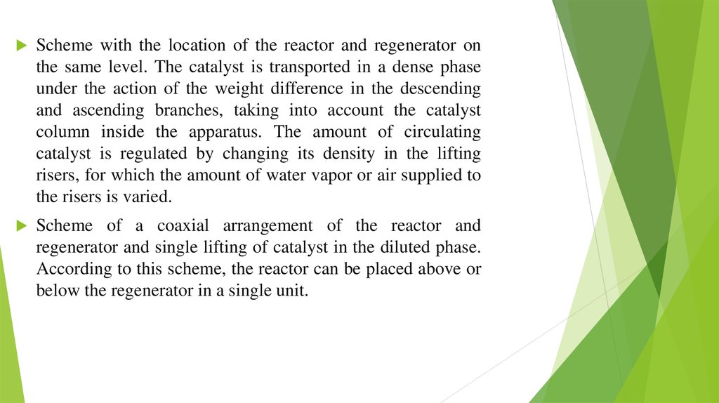
Scheme with the location of the reactor and regenerator onthe same level. The catalyst is transported in a dense phase
under the action of the weight difference in the descending
and ascending branches, taking into account the catalyst
column inside the apparatus. The amount of circulating
catalyst is regulated by changing its density in the lifting
risers, for which the amount of water vapor or air supplied to
the risers is varied.
Scheme of a coaxial arrangement of the reactor and
regenerator and single lifting of catalyst in the diluted phase.
According to this scheme, the reactor can be placed above or
below the regenerator in a single unit.
8.
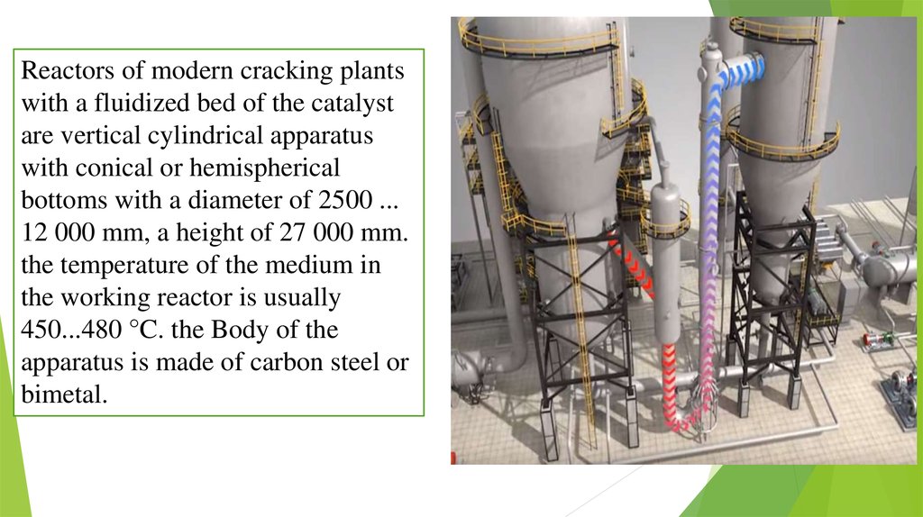
Reactors of modern cracking plantswith a fluidized bed of the catalyst
are vertical cylindrical apparatus
with conical or hemispherical
bottoms with a diameter of 2500 ...
12 000 mm, a height of 27 000 mm.
the temperature of the medium in
the working reactor is usually
450...480 °C. the Body of the
apparatus is made of carbon steel or
bimetal.
9.
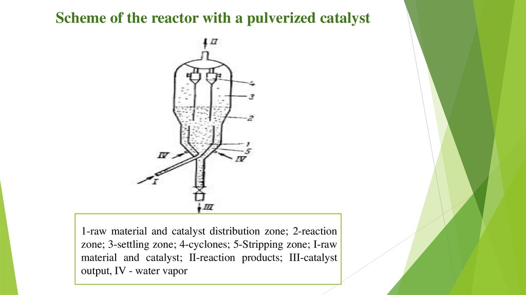
Scheme of the reactor with a pulverized catalyst1-raw material and catalyst distribution zone; 2-reaction
zone; 3-settling zone; 4-cyclones; 5-Stripping zone; I-raw
material and catalyst; II-reaction products; III-catalyst
output, IV - water vapor
10.
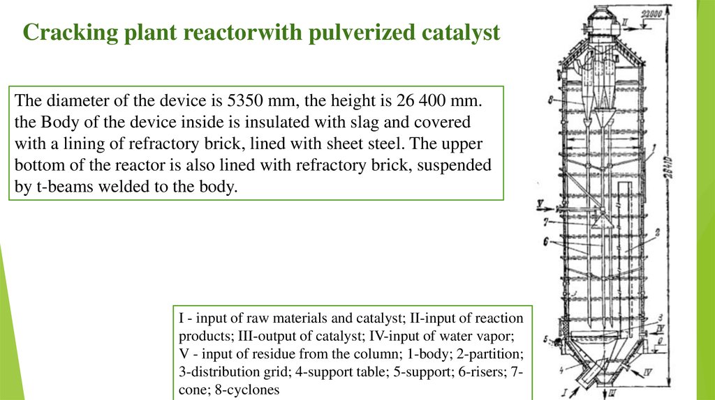
Cracking plant reactorwith pulverized catalystThe diameter of the device is 5350 mm, the height is 26 400 mm.
the Body of the device inside is insulated with slag and covered
with a lining of refractory brick, lined with sheet steel. The upper
bottom of the reactor is also lined with refractory brick, suspended
by t-beams welded to the body.
I - input of raw materials and catalyst; II-input of reaction
products; III-output of catalyst; IV-input of water vapor;
V - input of residue from the column; 1-body; 2-partition;
3-distribution grid; 4-support table; 5-support; 6-risers; 7cone; 8-cyclones