


 education
Similar presentations:


Arduino Basics. Goals of Lab #3
1. Lab 3: Arduino Basics
Prepared by senior-lecturer,B.B. Imankulova
2. Goals of Lab #3
● Learn how the programming takes place● Excercises about:
-Learn about Arduino electronics
-Learn about LEDs
-Learn how to code
3. Intro to Arduino
4. Installing the IDE
5. Connect your Arduino
6. The Arduino IDE
7. 1: Select serial port
8. 2: Select Arduino model
9. Programming an Arduino
From the File menu, choose Open and select thecode you want to open.
The source code will appear in the IDE window.
10. Programming workflow
11. Programming an Arduino
Click on the upload button and wait until the codehas been compiled and uploaded.
At the end you will see in the bottom right corner:
12. Programming an Arduino
This is the template of a basic Arduino program:13. Pre-lab #3
14.
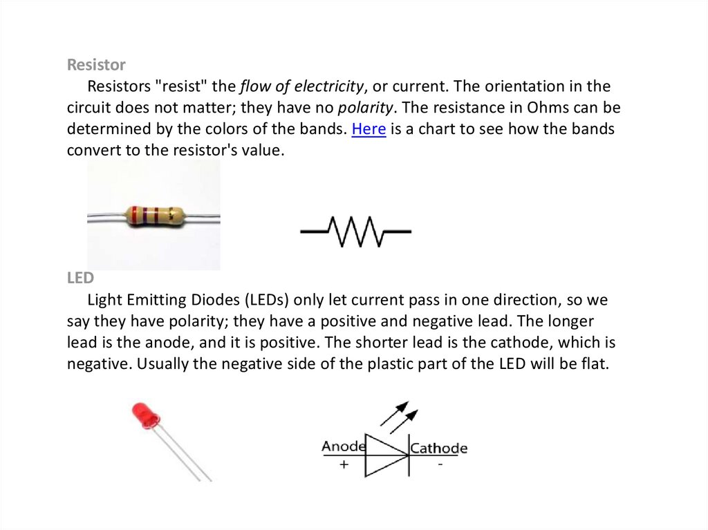
ResistorResistors "resist" the flow of electricity, or current. The orientation in the
circuit does not matter; they have no polarity. The resistance in Ohms can be
determined by the colors of the bands. Here is a chart to see how the bands
convert to the resistor's value.
LED
Light Emitting Diodes (LEDs) only let current pass in one direction, so we
say they have polarity; they have a positive and negative lead. The longer
lead is the anode, and it is positive. The shorter lead is the cathode, which is
negative. Usually the negative side of the plastic part of the LED will be flat.
15.
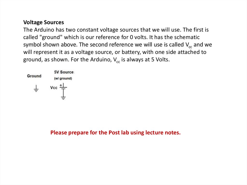
Voltage SourcesThe Arduino has two constant voltage sources that we will use. The first is
called "ground" which is our reference for 0 volts. It has the schematic
symbol shown above. The second reference we will use is called Vcc and we
will represent it as a voltage source, or battery, with one side attached to
ground, as shown. For the Arduino, Vcc is always at 5 Volts.
Please prepare for the Post lab using lecture notes.
16. Lab #3
17. Step 1: Connect the First LED to the Arduino
The first step is to connect the first LED to thecircuit and Arduino.
1. Place one LED on the breadboard and connect
the cathode to the negative rail of the breadboard.
2. Place a 220Ω resister on the anode leg of the LED
and connect the other end to pin 13 on the
Arduino.
3.Connect the negative rail on the breadboard to
the grounding pin on the Arduino.
18. Step 1: Connect the First LED to the Arduino
19. Schematic
20. CODE
21. Task #2 - Traffic Light Circuit
The equipment I have used in this Arduino traffic light project islisted right below.
• Arduino Uno
• Red, Yellow and green LED
• 3 x 220 Ohm resistors (Color = Brown Black Brown)
• Breadboard wires
• Breadboard
22. Step 1
• The circuit that we need to set up is really simpleand shouldn’t take you too long to do. It’s a fairly
simple setup with each pin controlling an LED.
• Pin 2 goes to the positive leg of the green LED.
• Pin 3 Goes to the positive leg of the yellow LED.
• Pin 4 goes to the positive leg of the red LED.
• Add a 220-ohm resistor to each of the negative
LED legs and have it go to GND.
23. Diagram
24. Code
// variables int GREEN = 2;
int YELLOW = 3;
int RED = 4;
int DELAY_GREEN = 5000;
int DELAY_YELLOW = 2000;
int DELAY_RED = 5000;
// basic functions void setup()
{ pinMode(GREEN, OUTPUT);
pinMode(YELLOW, OUTPUT);
pinMode(RED, OUTPUT);
}
void loop() {
green_light();
delay(DELAY_GREEN);
yellow_light();
delay(DELAY_YELLOW);
red_light();
delay(DELAY_RED);
}
25. Code
Now for each LED, we will need to create a function. As you can see the green_light() function will turn the green
LED on while turning the yellow and red LEDs off.
void green_light()
{
digitalWrite(GREEN, HIGH);
digitalWrite(YELLOW, LOW);
digitalWrite(RED, LOW);
}
void yellow_light()
{
digitalWrite(GREEN, LOW);
digitalWrite(YELLOW, HIGH);
digitalWrite(RED, LOW);
}
void red_light()
{
digitalWrite(GREEN, LOW);
digitalWrite(YELLOW, LOW);
digitalWrite(RED, HIGH);
}
26. Report
The report should include:1. front page and title
2. a code
2. photos of the scheme
3. conclusion
Please prepare for the Post lab using lecture notes.