


")
")
")
")


 mathematics
Similar presentations:


Index of Refraction
1. Index of Refraction
Jing LiOutline
•Introduction
•Classical Model
•Typical measurement methods
•Application
•Reference
2. Definition of Index of Refraction
In uniform isotropic linear media, the wave equation is:2
E E
0
2
t
2
2
H H
0
t 2
2
They are satisfied by plane wave
y=A e i(k r- wt)
k k ω
y can be any Cartesian components of E and H
The phase velocity of plane wave travels in the direction of k is
v ω 1
k
3. Definition of Index of Refraction
We can define the index of refraction asn v
c
0 0
Most media are nonmagnetic and have a magnetic permeability 0,
in this case
n
0
In most media, n is a function of frequency.
4. Classical Electron Model ( Lorentz Model)
w0Let the electric field of optical wave in an atom be
E=E0
e-iwt
the electron obeys the following equation of
motion
2
2
m d 2 X m d X mw0 X eE
dt
dt
X is the position of the electron relative to the atom
m is the mass of the electron
w0 is the resonant frequency of the electron motion
is the damping coefficient
- X
+
E
5. Classical Electron Model ( Lorentz Model)
The solution isX
eE0
iwt
e
2
m(w0 w 2 iw )
The induced dipole moment is
2
e
p eX
E E
2
2
m(w 0 w iw )
is atomic polarizability
2
e
2
m(w 0 w 2 iw )
The dielectric constant of a medium depends on the manner in which
the atoms are assembled. Let N be the number of atoms per unit
volume. Then the polarization can be written approximately as
P = N p = N E = 0 c E
6. Classical Electron Model ( Lorentz Model)
The dielectric constant of the medium is given by= 0 (1+c) = 0 (1+N / 0)
If the medium is nonmagnetic, the index of refraction is
n= ( / 0)1/2 = (1+N / 0 )1/2
2
Ne
n 1
0
0 m(w 0 2 w 2 iw )
2
If the second term is small enough then
2
Ne
n 1
2
2 0 m(w 0 w 2 iw )
7. Classical Electron Model ( Lorentz Model)
The complex refractive index isNe2 (w 0 w 2 )
Ne2 w
n nr ini 1
i
2
2
2 2
2 2
2 0 m[(w 0 w ) w ] 2 0 m[(w 0 w 2 ) 2 w 2 2 ]
2
at w ~w0 ,
Ne2 (w 0 w )
Ne2
nr ini 1
i
4 0 mw 0 [(w 0 w ) 2 ( / 2) 2 ] 8 0 mw 0 [(w 0 w ) 2 ( / 2) 2 ]
nr
ni
-6
-4
-2
0
2
4
6
(w-w0)/
Normalized plot of n-1 and k versus w w0
8.
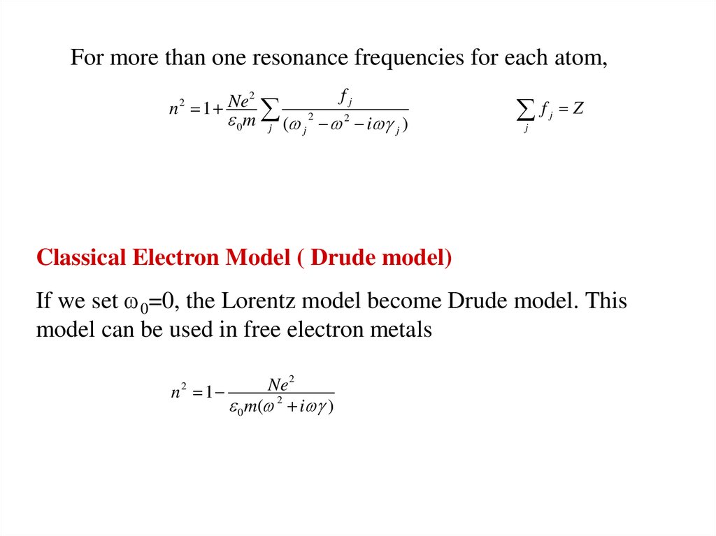
For more than one resonance frequencies for each atom,2
fj
n 2 1 Ne
0 m j (w j 2 w 2 iw j )
f
j
Z
j
Classical Electron Model ( Drude model)
If we set w0=0, the Lorentz model become Drude model. This
model can be used in free electron metals
n2 1
Ne2
0 m(w 2 iw )
9. Relation Between Dielectric Constant and Refractive Index
By definition,n2
0
n nr ini
1 i 2
We can easily get:
nr {1 [( 1 2 )1/ 2 1 ]}1/ 2 / 0
2
2
2
ni {1 [( 1 2 )1/ 2 1 ]}1/ 2 / 0
2
2
2
10. An Example to Calculate Optical Constants
Real and imaginary part of the index ofrefraction of GaN vs. energy;
11. Kramers-Kronig Relation
The real part and imaginary part of the complex dielectric function (w)are not independent. they can connected by Kramers-Kronig relations:
(w )w
2
1 (w ) 0 P 2 2
dw
0 w w 2
(w )
0
2 (w ) 2w P 1 2
dw
0 w w 2
P indicates that the integral is a principal value integral.
K-K relation can also be written in other form, like
n( ) 1 P
0
( )
d
2
1 ( / )
12. A Method Based on Reflection
Typical experimental setup( 1) halogen lamp;
(2) mono-chromator; (3) chopper; (4) filter;
(5) polarizer (get p-polarized light); (6) hole diaphragm;
(7) sample on rotating support (q); (8) PbS detector(2q)
13. Calculation
In this case, n1=1, and n2=nr+i n iSnell Law become:
z
E1'
k1z k2 z 2 sin q
Reflection coefficient:
n1 k2 x n2 k1x k2 x (nr ini ) 2 k1x
rp 2
2
2
n1 k2 x n2 k1x k2 x (nr ini ) k1x
2
2
n1=1
n2=nr+i n i
q
q
x
k1x [( 2 ) 2 2 ]1/ 2
k2 x [( 2 ) 2 (nr ini ) 2 2 ]1/ 2
Reflectance:
R(q1, , nr, n i)=|r p|2
E1
Reflection of p-polarized light
From this measurement, they got R, q for each wavelength ,
Fitting the experimental curve, they can get nr and n i .
14. Results Based on Reflection Measurement
Single effective oscillator modelnr 1
2
E0 Ed
2
E0 E 2
(Eq. 1)
Ef E
Ed E 2 Ed E 4
2
nr 1
ln(
)
3
2
2
E0
E0
E E
2
E f 2 E0 E
Ed
3
2
2
2E0 ( E0 E )
2
FIG. 2. Measured refractive indices at 300 K vs.
photon energy of AlSb and AlxGa1-xAsySb1-y
layers lattice matched to GaSb (y~0.085 x).
Dashed lines: calculated curves from Eq. ( 1);
Dotted lines: calculated curves from Eq. (2)
2
2
E0: oscillator energy
Ed: dispersion energy
E : lowest direct band gap energy
(Eq. 2)
15. Use AFM to Determine the Refractive Index Profiles of Optical Fibers
The basic configuration of optical fiber consistsof a hair like, cylindrical, dielectric region (core)
surrounded by a concentric layer of somewhat
lower refractive index( cladding).
n1
n2
2a
Fiber samples were
• Cleaved and mounted in holder
There is no way for AFM to measure
refractive index directly.
• Etched with 5% HF solution
People found fiber material with different • Measured with AFM
refractive index have different etch rate
in special solution.
16. AFM
•The optical lever operates by reflecting alaser beam off the cantilever. Angular
deflection of the cantilever causes a twofold
larger angular deflection of the laser beam.
• The reflected laser beam strikes a positionsensitive photodetector consisting of two
side-by-side photodiodes.
• The difference between the two photodiode
signals indicates the position of the laser spot
on the detector and thus the angular
deflection of the cantilever.
• Because the cantilever-to-detector distance
generally measures thousands of times the
length of the cantilever, the optical lever
greatly magnifies motions of the tip.
17. Result
18. A Method Based on Transmission
For q=0, input wave function a e if ,tm=aTT’R’2m-1 e i(f-(2m-1)d )
(m=1,2…)
d=2 dn/
The transmission wave
function is superposed by all tm
a T = a T T’ e if S m(R’2m-1 e-i(2m-1)d )
=(1-R2)a e i(f d) /(1-R2e-i2d)
(TT’=1-R2 ; R’=-R)
If R<<1, then
a T =a e i(f d)
maximum condition is 2d=2 m= 4 dn/
n( m)=m m/2d
r1 r2 r3
q
d
q1
d
n
t1 t2 t3
19. Result Based on Transmission Measurement
2n 2 2.27 2 304.7
2
294 2
20. Application
In our lab., we have a simple system to measure the thickness ofepitaxial GaN layer.
21. Thickness Measurement
n( m)=m m/2dSteps to calculate thickness
Intensity (A.U)
1.2
1.0
Get peak position m
d=( m m-1)/2/[ m-1 n( m) m n( m-1)]
Average d
get m min= n( max)*2d/ max
Calculate d : d=m m/2/n( m)
(from m min for each peak)
Average d again
0.8
0.6
400
450
500
550
600
Wavelength (nm)
Limit
Minimum thickness:~500/n
Error< /2n
22. Reference
1. Pochi Yeh, "Optical Wave in Layered Media", 1988, John Wiley &Sons Inc
2. E. E. Kriezis, D. P. Chrissoulidis & A. G. Papafiannakis,
Electromagnetics and Optics, 1992, World Scientific Publishing Co.,
3. Aleksandra B. Djurisic and E. H. Li, J. OF Appl. Phys., 85 (1999)
2848 (mode for GaN)
4. C. Alibert, M. Skouri, A. Joullie, M. Benounab andS. Sadiq , J. Appl.
Phys., 69(1991)3208 (Reflection)
5. Kun Liu, J. H. Chu, and D. Y. Tang, J. Appl. Phys. 75 (1994)4176
(KK relation)
6. G. Yu, G. Wang, H. Ishikawa, M. Umeno, T. Soga, T. Egawa, J.
Watanabe, and T. Jimbo, Appl. Phys. Lett. 70 (1997) 3209
7. Jagat, http://www.phys.ksu.edu/~jagat/afm.ppt (AFM)