

?")


")
")
")


")
")
")
")
")


")


 informatics
Similar presentations:


SOF108 - Computer Architecture Week 14: Parallel Processing – Pipelining
1. SOF108 - Computer Architecture Week 14: Parallel Processing – Pipelining
MALAYSIASOF108 - Computer Architecture
Week 14: Parallel Processing – Pipelining
1
2. Agenda
• Pipelining• Hazards in Pipeline
• Dependencies in Pipeline
• How to avoid hazards?
• Stall
• Forward
• Prediction
• Delayed branch
2
3. What is Instruction Level Parallelism (ILP)?
• Goal of ILP is to execute several instructions simultaneously to make theprogram run faster
• Some instructions are independent of others
• We don’t always have to wait for all previous instructions to execute before
executing a given instruction
• If independent instructions are executed in parallel, the program runs
faster
3
4. Increase Computer Performance
• Can be achieved by taking advantage of improvements in technology,such as faster circuitry
• In addition, organization enhancements to the processor can improve
performance
• We have seen some examples of this:
• Use of multiple registers rather than a single accumulator,
• use of cache memory
• Another common organizational approach is:
• Instruction Pipelining
4
5. Pipeline Strategy
• During the execution main memory is not accessed• While the second stage is executing, the first stage can utilize unused memory
cycles to fetch and buffer the next instruction
• This is called instruction prefetch or fetch overlap
• This will speed up instruction execution
5
6. Pipelining
• Decompose a sequential process into sub-operation, with each suboperation completed in dedicated segment.• It is similar like assembly line of car manufacturing.
• First station in an assembly line installing the engine, next station is
fitting the body, another group of workers working on the paint.
6
7. Pipelining in Assembly Line
78. Pipelining Laundry Example: It is Natural
• Ann, Brian, Cathy, Daveeach have one load of clothes
to wash, dry, and fold
A
B
C
D
• Washer takes 30 minutes
• Dryer takes 40 minutes
• “Folder” takes 20 minutes
8
9. Sequential Laundry
• Sequential laundry (without pipelining) takes 6 hours for 4 loads• If they learned pipelining, how long would laundry take?
9
10.
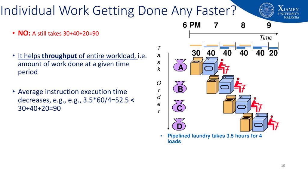
Individual Work Getting Done Any Faster?6 PM
• NO: A still takes 30+40+20=90
• It helps throughput of entire workload, i.e.
amount of work done at a given time
period
• Average instruction execution time
decreases, e.g., e.g., 3.5*60/4=52.5 <
30+40+20=90
7
8
9
Time
T
a
s
k
O
r
d
e
r
30 40
40
40
40 20
A
B
C
D
Pipelined laundry takes 3.5 hours for 4
loads
10
11. Pipelining
• An implementation technique wherebymultiple instructions are overlapped in
execution.
e.g., B wash while A dry
A
B
• Essence: Start executing one instruction
before completing the previous one.
• Significance: Make fast CPUs.
11
12. Balanced Pipeline
• Equal-length pipe stagese.g., Wash, dry, fold = 40 mins
per unpipelined laundry time = 40x3 mins
3 pipe stages – wash, dry, fold
40min
T1
T2
T3
T4
A
B
C
D
A
B
C
A
B
12
13. Balanced Pipeline
• Equal-length pipe stagese.g., Wash, dry, fold = 40 mins
per unpipelined laundry time = 40x3 mins
3 pipe stages – wash, dry, fold
40min
T1
T2
T3
T4
A
B
C
D
A
B
C
A
B
13
14. Balanced Pipeline
• Equal-length pipe stagese.g., Wash, dry, fold = 40 mins
per unpipelined laundry time = 40x3 mins
3 pipe stages – wash, dry, fold
40min
T1
T2
T3
T4
A
B
C
D
A
B
C
A
B
14
15. Balanced Pipeline
One task/instructionper 40 mins
• Equal-length pipe stages
e.g., Wash, dry, fold = 40 mins
per unpipelined laundry time = 40x3 mins
3 pipe stages – wash, dry, fold
• Performance
40min
T1
T2
T3
T4
A
B
C
D
A
B
C
Time per instruction by pipeline =
Time per instr on unpipelined machine
Number of pipeline stages
A
B Speed up by pipeline≡Number of pipe stages
15
16. Pipelining Performance
• Each instruction is split up into a sequence of steps – different steps can be executedconcurrently by different circuitry.
• The potential increase in performance resulting from pipelining is proportional to the
number of pipeline stages.
• However, this increase would be achieved only if all pipeline stages require the same
time to complete, and there is no interruption throughout program execution.
• Unfortunately, this is NOT true.
• Pipeline rate limited by slowest pipeline stage.
• Unbalanced lengths of pipe stages reduces speedup
• Effect of branching
16
17. 6 stage Instruction Cycle
1.Fetch instruction (FI): read the next expected instruction into a buffer
2.
Decode instruction (DI): determine the opcode and the operand specifiers
3.
Calculate operands (CO): Calculate the effective address (EA) of each source operand
4.
Fetch operands (FO): Fetch operand from memory.
5.
Execute instructions (EI): Perform the indicated operation and store the result, if any, in
the specified destination operand location
6.
Write result (WO): Store the result in memory
17
18. Pipelining - A 6 stage Instruction Cycle
1819. An Alternative Pipeline Depiction
• Pipeline stages are full at cycle 6• Every stage is doing something
• Once the pipeline is full, one instruction gets out
of the pipeline at each cycle
19
20. Pipelining - A 6 stage Instruction Cycle
• The diagram assumes that each instruction goes through all six stagesof the pipeline
• NOT always be the case, e.g., load instruction does not need the WO stage
• Assumes that all the stages can be performed in parallel
• Assumes no memory conflict FI, FO, and WO stages involve memory access
• Most memory system will not permit that
• But the desired value may be in the cache, or the FO or WO stage may be null
• Much of the time, this will not slow down the pipeline
20
21. Pipelining - A 6 stage Instruction Cycle
• If the six stages are not of equal duration, there will be some waiting involved atvarious pipeline stages
• Another difficulty is conditional branch instruction
• Can invalidate several instruction fetches
• The CO stage may depend on the contents of a register that could be altered by a
previous instruction that is still in the pipeline
• Other such register and memory conflict may occur
• The system must contain logic for this type of conflicts
21
22. Effect of An Unbalanced Pipeline Stages
2223. Effect of a Conditional Branch Instruction
• Lets consider that Instruction 3 is a conditional branch to Instruction15
23
24. What determines Pipeline Performance?
DependencesA dependence is a property of the instructions in a program
Hazards
• Occurs when the pipeline, or some portion of the pipeline must stall (pause)
• because conditions do not permit continued execution. This is also referred to as a pipeline bubble
• Hazards prevent next instruction from executing during its designated clock cycle:
• causes degradation in pipeline performance.
• We need to identify all hazards that may cause the pipeline to stall and to find ways to
minimize their impact.
24
25. Pipeline Hazard
• Three types• Resource hazard/ Structural hazard
• Data hazard
• Control hazard
25
26. Resource Hazard/Structural hazard
• A resource hazard occurs when two (or more instructions) that arealready in the pipeline need the same resource
• Requires serial execution rather than parallel for a portion of the pipeline
• If some combination of instructions cannot be accommodated
because of resource conflicts (hardware conflicts), the machine is
said to have structural hazard/ resource hazard.
26
27. Example of Resource Hazard
• Main memory has a single port• Operand for I1 is located in
memory
• All other operands are in
registers
• Any problem here?
• One solutions to this type of
resource hazards is to increase
available resources
• having multiple ports into main
memory
27
28. Example of Resource Hazard
• Another example of a resource conflict is a situation in which multipleinstructions are ready to enter the execute instruction phase and
there is a single ALU.
• One solutions to such resource hazards is to increase available
resources,
• having multiple ALU units.
28
29. Data Hazard
• Data hazard occurs when there is a conflict in the access of anoperand location.
• Generally, Data hazards arise when an instruction depends on the
results of a previous instruction in a way that is exposed by the
overlapping of instructions in the pipeline
29
30. Example of Data Hazard
• Consider the following x86 machine instruction sequence:ADD EAX, EBX
# EAX = EAX + EBX
SUB ECX, EAX
# ECX = ECX - EAX
30
31. Data Hazards
• Three types of data hazards:• Read after write (RAW), or true dependency
• Write after read (WAR), or antidependency
• Write after Write (WAW), or output dependency
31
32. Read after Write (RAW)
• An instruction modifies (writes) a register or memory location and asucceeding instruction reads the data in that memory or register
location
• A hazard occurs if the read takes place before the write operation is
complete.
• Example:
• Add R1, R2, R3
• Add R4, R1, R5
32
33. Write after Read (WAR)
• An instruction reads a register or memory location and a succeedinginstruction writes to the location
• A hazard occurs if the write operation completes before the read
operation takes place
• Example:
• I: sub r4, r1, r3
• J: add r1, r2, r3
• K: mul r6, r1, r7
33
34. Write after Write (WAW)
• Two instructions both write to the same location• A hazard occurs if the write operations take place in the reverse order
of the intended sequence
• Example:
• I: sub r1, r4, r3
• J: add r1, r2, r3
• K: mul r6, r1, r7
34
35. What type of data dependency is this one?
• Is there any dependencies?• YES!
• True data dependency/ Read
after write (RAW)
Write into
• Example
Read from
35
36. What type of data dependency is this?
• Example:R2 R4 + R7 ;instruction 1
R2 R1 + R3 ;instruction 2
• Write after write (WAW) dependency/ output dependency
36
37. What type of data dependency is this?
• ExampleR2 R1 + R3 ; Instruction 1: Read R3
R3 R4 + R5 ; Instruction 2: Write R3
• Write After Read (WAR) dependency/ Antidependency
37
38. Control Hazards
• A control hazard, also known as a branch hazard,• occurs when the pipeline makes the wrong decision on a branch prediction and therefore brings
instructions into the pipeline that must subsequently be discarded.
• In a branch, we do not know the next instruction that will be executed - until it is
resolved.
• The pipeline cannot legitimately work on a following instruction until then - so it is
stalled.
• This can slow down significantly.
38
39. Control Hazard Dependencies
• Data dependency:• one instruction is dependent on another instruction to provide its operands.
• Control dependency (aka branch dependences):
• one instructions determines whether another gets executed or not.
add $5, $3, $2
data dependences
sub $6, $5, $2
beq $6, $7, somewhere
control dependence
Next instruction(s):……
somwhere: and $9, $3, $1
39
40. Control Hazard Example
• Lets consider thatInstruction 3 is a
conditional branch
to Instruction 15
• Assume that the
output of the branch
is known only after
the execution stage
• Let the pipeline
predict that the
branch is not taken
40
41. An Alternative Pipeline Depiction
42. MIPS Pipeline Datapath
• Five stages, one step per stage• IF: Instruction fetch from memory
• ID: Instruction decode and register read
• EX: Execute operation or calculate
address
• MEM: Access memory operand
• WB: Write result back to register
42
43. Pipeline: Number of Stages?
• Bigger the better?• From the preceding discussion, it may appear that the larger the
number of stages in the pipeline, the faster the execution rate.
• Speed up by pipeline ≡ Number of pipe stages
• However, there are some additional things that we need to consider!
43
44. Pipeline: Number of Stages?
• At each stage, there is some overhead involved in moving data from bufferto buffer, and in performing various preparation and delivery functions.
• This overhead can appreciably lengthen the total execution time of a single
instruction
• The amount of control logic increases enormously with the number of
stages
• required to handle memory and register dependencies and
• to optimize the use of the pipeline
44
45. Uniformity is Simplicity
• Enforce Uniformity• Make all instructions take five cycles
• Make them have the same stages, in the same order
• Some stages will do nothing for some instructions
45
46. A Simple Implementation of a RISC Instruction
• Every instruction in MIPS can be implemented in at most 5 clock cycles. The 5 clockcycles are:
• Instruction fetch cycle (IF)
• Instruction decode/ register fetch cycle (ID)
• Execution/effective address cycle (EX)
• Memory access (MEM)
• Write-back cycle (WB)
46
47. Instruction Fetch Cycle (IF)
• Send the program counter (PC) to memory and fetch the currentinstruction from memory.
• IR:= Memory[PC]
• Update the PC to the next sequential PC by adding 4 (since each
instruction is 4 bytes) to the PC.
• PC:= PC+4
47
48. Instruction Decode/Register Fetch cycle (ID)
• Decode the instruction and read the registers corresponding to registersource specifiers from the register file.
• ADD R1, R2, R3
• Do the equality test on the registers as they are read, for a possible branch.
• BEQ R1, R2, 5
• Decoding is done in parallel with reading registers
48
49. Execution/Effective Address Cycle (EX)
• Memory reference: The ALU adds the base register and the offset to form theeffective address. For example:
• LW R1, 0(R2)
• SW R4,12(R1)
• Register-Register ALU instruction: The ALU performs the operation specified by
the ALU opcode on the values read from the register file. For example:
• ADD R4, R1, R5
• Register-Immediate ALU instruction: The ALU performs the operation specified by
the ALU opcode on the first value read from the register file and the signextended immediate.
• ADDI R4, R1, 15
49
50. Memory Access (MEM)
• If the instruction is a load, memory does a read using the effectiveaddress computed in the previous cycle.
• LW R1, 0(R2)
• If it is a store, then the memory writes the data from the second
register read from the register file using the effective address.
• SW R4,12(R1)
50
51. Write-Back Cycle (WB)
• Register-Register ALU instruction or• Write the result into the register file from the ALU (for an ALU instruction)
• ADD R4, R1, R5
• Load instruction
• Write the result into the register file from the memory system (for a load)
• LW R1, 0(R2)
51
52. Five-Stage Pipeline for RISC Processor
Decode instr,Read
LW R1, 0(R2) read R2
Mem[0+R2] Write
Fetch the
instruction
Calculate
0+R2
Mem[0+R2]
into R1
52
53. A Simplified Version of a RISC Data Path Drawn in Pipeline Fashion
Figure C.2 The pipeline can bethought of as a series of data
paths shifted in time. This shows
the overlap among the parts of the
data path, with clock cycle 5 (CC 5)
showing the steady-state situation.
Because the register file is used as a
source in the ID stage and as a
destination in the WB stage, it
appears twice. We show that it is
read in one part of the stage and
written in another by using a solid
line, on the right or left,
respectively, and a dashed line on
the other side. The abbreviation IM
is used for instruction memory, DM
for data memory, and CC for clock
cycle.
53
54. Observation 1
• Separate instruction and• data memories
• Eliminates a conflict for a
single memory
• instruction fetch
memory access
and
data
54
55. Observation 2
• Register file is used in twostages
• Reading in ID
• Writing in WB
• Reads and a write to the
same register
• Register write in the first half
of the clock cycle and
• the read in the second half
55
56. Intermediate Pipeline Registers are Necessary
IF/IDID/EX
EX/MEM
MEM/WB
Figure C.3 A pipeline
showing
the
pipeline
registers between successive
pipeline stages. Notice that
the
registers
prevent
interference between two
different
instructions
in
adjacent stages in the pipeline.
The registers also play the
critical role of carrying data
for a given instruction from
one stage to the other.
56
57. Why Intermediate Registers?
• Sometimes we need the outputof a functional unit in a later clock
cycle during the execution of an
instruction.
Read the value
of register R4 in
this stage
Uses the value
of register R4 in
this stage
- Register value to be stored during
a store instruction is read during ID,
but not actually used until MEM
- SW R4,12(R1)
57
58. Why Intermediate Registers?
• Sometimes we need the outputof a functional unit in a later clock
cycle during the execution of an
instruction.
Compute the value
of register R1+R5
in this stage
Write the result in
R4 in this stage
- the result of an ALU instruction is
computed during EX, but not
actually stored until WB
-ADD R4, R1, R5
58
59. Basic Performance Issues in Pipelining
• Pipelining increases the CPU instruction throughput• the number of instructions completed per unit of time
• but it does not reduce the execution time of an individual instruction.
• In fact, it usually slightly increases the execution time of each
instruction due to overhead in the control of the pipeline.
• The increase in instruction throughput means that
• a program runs faster and has lower total execution time,
• even though no single instruction runs faster!
59
60. Pipeline is not Quite that Easy!
• Limits to pipelining: Hazards prevent next instruction from executing duringits designated clock cycle
• Structural hazards: hardware cannot support all possible combinations of
instructions simultaneously in overlapped execution.
• Data hazards: instruction depends on the results of a previous instruction
still in the pipeline.
• Control hazards: arise from the pipelining of branches and other
instructions that change the PC.
60
61. Major Hurdle of Pipelining – Pipeline Hazards
• Hazards in pipelines can make it necessary to stall the pipeline.• Avoiding a hazard often requires that
• some instructions in the pipeline be allowed to proceed
• while others are delayed.
• For the pipelines we discuss in this course, when an instruction is stalled, all
instructions issued later than the stalled instruction—and hence not as far along
in the pipeline—are also stalled.
• Instructions issued earlier than the stalled instruction—and hence farther along
in the pipeline—must continue, since otherwise the hazard will never clear. As a
result, no new instructions are fetched during the stall.
61
62. Structural Hazards
Figure C.4 A processorwith only one memory
port will generate a
conflict whenever a
memory reference
occurs. In this example
the load instruction uses
the memory for a data
access at the same time
instruction 3 wants to
fetch an instruction
from memory.
62
63. Structural Hazards
• When a sequence of instructions encounters this hazard, the pipelinewill stall one of the instructions until the required unit is available.
• Such stalls will increase the CPI from its usual ideal value of 1.
• Assume, the first instruction
is load. The rest of the
instructions are registerregister ALU instructions.
• Why instruction i+4 does
not require a stall?
63
64. Data Hazards
• Is there any dependencies in the following example? Hazard?DADD R1, R2, R3
DSUB R4, R1, R5
AND R6, R1, R7
OR R8, R1, R9
XOR R10, R1, R11
*DADD Same as MIPS addition, but for a double word
64
65. Data Hazards
I1 writes/updates the value of R1 in hereNeed the updated value of R1 in here
Figure C.6 The use of the
result of the DADD
instruction in the next
instructions may cause a
hazard, since the register
is not written until after
those instructions read it.
65
66. Minimizing Data Hazards Stalls by Forwarding
Need to use the updated value of R1 in here• The problem posed in Figure C.6 can be Produces the updated
solved with a simple hardware technique value of R1 in here
called forwarding (also called bypassing
and sometimes short-circuiting).
• Key insight:
• The result is not really needed by the DSUB
until after the DADD actually produces it.
• If the result can be moved from the pipeline
register where the DADD stores it to where the
DSUB needs it, then the need for a stall can be
avoided.
66
67. Minimizing Data Hazards Stalls by Forwarding
• Based on the insights from the previous slide, forwarding works asfollows:
• The ALU result from both the EX/MEM and MEM/WB pipeline registers is
always fed back to the ALU inputs.
• If the forwarding hardware detects that the previous ALU operation has
written the register corresponding to a source for the current ALU operation,
• control logic selects the forwarded result as the ALU input rather than the value read
from the register file.
67
68. Minimizing Data Hazards Stalls by Forwarding
Figure C.7 A set of instructions thatdepends on the DADD result uses
forwarding paths to avoid the data
hazard. The inputs for the DSUB and
AND instructions forward from the
pipeline registers to the first ALU
input. The OR receives its result by
forwarding through the register file,
which is easily accomplished by
reading the registers in the second
half of the cycle and writing in the
first half, as the dashed lines on the
registers indicate. Notice that the
forwarded result can go to either ALU
input; in fact, both ALU inputs could
use forwarded inputs from either the
same pipeline register or from
different pipeline registers. This
would occur, for example, if the AND
instruction was AND R6,R1,R4.
68
69. Can We use Forwarding for All Data Hazards?
• Consider the following sequence of instructions:LD R1, 0(R2)
DSUB R4, R1, R5
AND R6, R1, R7
OR R8, R1, R9
• What are the data hazards?
*LD Same as MIPS LW, but for a double word
69
70. Can We use Forwarding for All Data Hazards?
Produces the updatedvalue of R1 in here
Need to use the updated value of R1 in here
Figure C.9 The load
instruction can bypass
its results to the AND
and OR instructions,
but not to the DSUB,
since that would mean
forwarding the result
in “negative time.”
70
71. Data Hazards Requiring Stalls
Can not forward the result while it is beingproduced (can not forward in a negative time)
Figure C10(a): The MEM cycle of the load produces a value that is needed in the EX cycle of the DSUB,
which occurs at the same time
• Hardware called a pipeline interlock must be added to detect a hazard and stall
the pipeline until it is cleared.
71
72. Data Hazards Requiring Stalls
Forward the updated value of R1in here (after one cycle stall)
Figure C10(b): Resolution of the problem with a stall
• CPI for the stalled instruction increases by the length of the stall (1 clock cycle in this case)
• Forwarding to AND goes through the register cyle because the stall causes instructions starting
with DSUB to move 1 cycle later
72
73. Control Hazards
• Control hazard Also called branch hazard.• if a branch changes the PC to its target address, it is a taken branch;
• if it falls through, it is not taken, or untaken.
• Laundry analogy:
• Cleaning uniforms of a football team
• Detergent and water temperature setting we select is strong enough?
• Need to wait until after the second stage to examine the dry uniform to see if we need to
change the washer setup or not. What to do?
• Branch instructions in a computer
• Begin fetching the instruction following the branch on the very next clock cycle.
• The pipeline cannot possibly know what the next instruction should be, since it only just
received the branch instruction from memory!
73
74. Reducing Pipeline Branch Penalties
• We discuss four simple compile time schemes here:• Freeze or Flush (Stall)
• Predicted-not-taken or predicted-untaken
• Predicted-taken
• Delayed branch
74
75. Control Hazards
• Solution 1 – Stall: Just operate sequentially until the first batch is dry and then repeatuntil you have the right formula.
• Just as with laundry, one possible solution is to stall immediately after we fetch a branch,
waiting until the pipeline determines the outcome of the branch and knows what
instruction address to fetch from.
MIPS pipeline knows the
outcome of the branch at ID
stage
Which instruction
to fetch in this
cycle?
Delay/ stall the
pipeline until
resolved
75
76. Control Hazards
• Solution 2 – Predict: If you’re pretty sure you have the right formulato wash uniforms, then just predict that it will work and wash the
second load while waiting for the first load to dry.
• Computers do indeed use prediction to handle branches. One simple
approach is to predict always that branches will be untaken.
• When you’re right, the pipeline proceeds at full speed.
• Only when branches are taken does the pipeline stall.
76
77. Control Hazards – Branch Prediction
Fetched wrong instructionbecause of misprediction.
• Predicted-not-taken or predicted-untaken
Fetched the correct instruction as soon
as the branch outcome is known (after
the decode stage for MIPS).
77
78. Control Hazards – Branch Prediction
• Predicted-taken• An alternative scheme is to treat every branch as taken
The branch predicts that it will be taken, but to fetch the
branch target we need to know what is the target
address! And the target address is known in the decode
stage, where we also know the branch outcome.
• As soon as the branch is decoded and the target address is computed, we assume the branch
to be taken and begin fetching and executing at the target
• Any advantages of predicted taken for MIPS?
• Because in our five-stage pipeline we don't know the target address any earlier than we know
the branch outcome, there is no advantage in this approach for this pipeline.
• In some processors the branch target is known before the branch outcome, and a predictedtaken scheme might make sense.
??
78
79. Other types of Branch Prediction
• A more sophisticated version of branch prediction would have somebranches predicted as taken and some as untaken.
• Laundry analogy:
• the dark or home uniforms might take one formula while the light or road
uniforms might take another.
• In the case of programming,
• at the bottom of loops are branches that jump back to the top of the loop.
Since they are likely to be taken and they branch backward, we could always
predict taken for branches that jump to an earlier address
79
80. Control Hazards – Delayed Decisions
• Laundry analogy:• Place a load of non-football clothes in the washer while waiting for football
uniforms to dry.
• delayed branch
• used by the MIPS architecture
• always executes the next sequential instruction
• with the branch taking place after that one instruction delay
80
81. Control Hazards – Delayed Branch
• The add instruction before the branch in Figure 4.31 does not affectthe branch and can be moved after the branch to fully hide the
branch delay.
81
82. Control Hazards – Delayed Branch
• Delayed branch – A delayed branch always executes the followinginstruction, but the second instruction following the branch will be affected
by the branch.
• Branch delay slot – The slot directly after a delayed branch instruction,
which in the MIPS architecture is filled by an instruction that does not
affect the branch.
If branch taken, execution is:
Branch instruction
Branch delay instruction
Branch target
(depending on the outcome
of the decoding stage)
If branch not taken, execution is:
Branch instruction
Branch delay instruction
Next Instruction after branch
(depending on the outcome of
the decoding stage)
82
83. Control Hazards – Delayed Branch
The instructions in thedelay slot (there is only
one delay slot for MIPS)
are executed. If the
branch is untaken,
execution continues
with the instruction after
the branch delay
instruction; if the branch
is taken, execution
continues at the branch
target.
83
84. Reducing the Branch Cost through Prediction
• As pipeline gets deeper and potential penalty of branches increases,using delayed branches and similar schemes becomes insufficient.
• Requires more aggressive means:
• Static branch prediction
• Dynamic branch prediction
84
85. Integrated Circuit (IC)
8586. Now we can define Computer Architecture?
• What is computer architecture?• Computer architecture is the organisation of the components which
make up a computer system and the meaning of the operations which
guide its function.
• It defines what is seen on the machine interface, which is targeted by
programming languages and their compilers.
86
87. Summary
• Use pipeline for performance. Three kinds of hazards conspire to make pipelining difficult.• Structural hazards result from not having enough hardware available to execute multiple
instructions simultaneously.
• Data hazards can occur when instructions need to access registers that haven’t been updated yet.
• Control hazards arise when the CPU cannot determine which instruction to fetch next.
• How to avoid hazards?
Stall
Forward
Prediction
Delayed branch
87
88.
Appendix: University's vision and missionVision
Xiamen University Malaysia aspires to become a university with a
distinct global outlook, featuring first-class teaching and research, and
embracing cultural diversity.
Mission
To nurture young talents with dignity and wisdom, turning them into
fine citizens of the region who will contribute to the prosperity of the
people and social progress of Malaysia, China and Southeast Asia.
88