


 informatics
Similar presentations:


Bus-modular structure of the PC Von Neumann Architecture
1. Bus-modular structure of the PC Von Neumann Architecture
2. Learning objectives
show understanding of how data are transferred between variouscomponents of the computer system using the address bus, data bus and
control bus
explain the concept that data and instructions are stored in memory and
processed by the CPU
3. Von Neumann Architecture
4. Von Neumann Architecture
• The memory unit that holds both data and instructions.• The arithmetic/logic gate unit that is capable of performing
arithmetic and logic operations on data.
• The input unit that moves data from the outside world into the
computer.
• The output unit that moves results from inside the computer to
the outside world.
• The control unit that acts as the stage unit to ensure that all
the other components act in concert.
5.
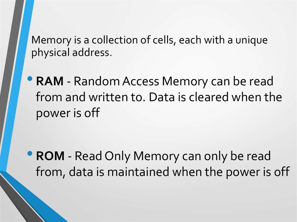
Memory is a collection of cells, each with a uniquephysical address.
• RAM - Random Access Memory can be read
from and written to. Data is cleared when the
power is off
• ROM - Read Only Memory can only be read
from, data is maintained when the power is off
6. Input/Output Units
• An Input Unit is a device through which data and programsfrom the outside world are entered into the computer.
• An Output Unit is a device through which results stored in the
computer memory are made available to the outside world.
Examples include printers and screen monitors.
7. Arithmetic/Logic Unit
The ALU is a fundamental building block in the centralprocessing unit (CPU) of a computer and without it the
computer wouldn't be able to calculate anything!
The Arithmetic Logic Unit or the ALU is a digital circuit that
performs arithmetic and logical operations. Where arithmetic
operations include things such as ADD and SUBTRACT and the
logical operations include things such as AND, OR, NOT.
8. Control unit
The control unit sits inside the CPU and coordinates the inputand output devices of a computer system. It coordinates the
fetching of program code from main memory to the CPU and
directs the operation of the other processor components by
providing timing and control signals.
9. Bus-modular structure of the PC
10. LMC CPU Structure
• Visible registersshown in red
Accumulator
• Accumulators
ALU
• Data for
calculation
ALU
• Data
• Word to/from
memory
data
MEM Data
• PC
Control Unit
Instruction
Control
Unit
Program
Counter
Mem
Addres
s
address
• Address of next
instruction
m
e
m
o
r
y
• Instruction
• Address
• For memory
access
11. Registers
Registers - a small amount of fast storage which is part of the processorProgram Counter (PC) - an incrementing counter that keeps track of the memory
address of which instruction is to be executed next.
Memory Address Register (MAR) - holds the address in memory of the next instruction
to be executed
Memory Buffer Register (MBR) - a two-way register that holds data fetched from
memory (and ready for the CPU to process) or data waiting to be stored in memory
Current Instruction register (CIR) - a temporary holding ground for the instruction that
has just been fetched from memory
12. Processor clock
Processor clockA timing device connected to the processor that synchronises
when the fetch, decode execute cycle runs.
Your computer might contain several clocks that each
regulate different things. The clock we are going to look at
here will keep the processor in line. It will send the processor
a signal at regular times telling it to start the fetch decode
execute routine.
Clock speed - The number of cycles that are performed by
the CPU per second.
13. System Bus
A Bus is a connection between different devices. This connection willnormally consist of multiple wires along which signals, instructions and data
will be carried.
In Von Neumann Architecture there is a single bus to manage the
connection between the three main components. The System Bus consists
of 3 separate buses, each with a specific task that you need to know.
This three bus model is an expansion of the Von Neumann architecture
showing greater detail.
14. Address Bus
A single-directional bus that carries address signals from theCPU to Main Memory and I/O devices.
This might involve the CPU requesting some data from Main
Memory, sending the address of the data to Main Memory,
then Main Memory returning the data along the data bus.
15. Data bus
A bi-directional bus, typically consisting of 32 wires, used totransport data and instructions between the three
components of the three-box model. The larger the Data Bus
the more data can be transported at one time.
16. Control bus
A bi-directional bus, typically consisting of more than 16wires, used to transport control signals between the three
components of the three-box model. The control bus is used
to carry important information such as messages to say when
a device has finished a job or when a device has just been
plugged in.
A simple example would be when you plug in your USB key
and after a few moments a screen pops up asking you what
you want to do with it.
17.
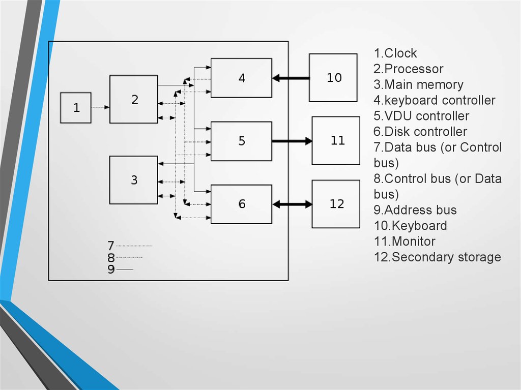
1.Clock2.Processor
3.Main memory
4.keyboard controller
5.VDU controller
6.Disk controller
7.Data bus (or Control
bus)
8.Control bus (or Data
bus)
9.Address bus
10.Keyboard
11.Monitor
12.Secondary storage
18. Fetch-Execute
• Each instruction cycle consists on two subcycles• Fetch cycle
• Load the next instruction (Opcode + address)
• Use Program Counter
• Execute cycle
• Control unit interprets the opcode
• ... an operation to be executed on the data by the ALU
Start
Fetch next
instruction
Decode &
execute
instruction
Halt
19. Fetch Instruction
AccumulatorsALU
ALU
Data
4
Instruction
3
data
Control Unit
Program
Counter
1
Control
Unit
Address
address
2
m
e
m
o
r
y
1. Program
counter to address
register
2. Read memory at
address
3. Memory data to ‘Data’
4. ‘Data’to
instruction
register
5. Advance
program
counter
20. Execute Instruction
Accumulators6
ALU
5
ALU
5
4
data
Data
2
Instruction
Control Unit
Program
Counter
1
Control
Unit
Address
address
3
m
e
m
o
r
y
1.
2.
Decode instruction
3.
4.
Access memory
5.
Add (e.g.) data and
accumulator value
6.
Update
Address from instruction
to ‘address register’
Data from memory to ‘data
register’
accumulator
21. The Fetch-Execute Cycle
The process cycle includes four steps:1.Fetch the next instruction,
2.Decode the instruction
3.Get data if needed,
4.Execute the instruction.
22. Fetch the Next Instruction
The PC increments one by one to point to the next instructionto be executed, so the control unit goes to the address in the
memory address register which holds the address of the next
instruction specified in the PC, takes it to the main memory
through the address bus and returns it to the memory buffer
register via the data bus.
23. Decode the Instruction
To execute the instruction in the instruction register, thecontrol unit has to determine what instruction it is. It might be
an instruction to access data from an input device, to send
data to an output device, or to perform some operation on a
data value. At this phase, the instruction is decoded into
control signals.
24. Get Data If Needed
The instruction to be executed may potentially requireadditional memory accesses to complete its task. For example,
if the instruction says to add the contents of a memory
location to a register, the control unit must get the contents of
the memory location.
25. Execute the Instruction
Once an instruction has been decoded and any operands (data)fetched, the control unit is ready to execute the instruction.
Execution involves sending signals to the arithmetic/logic unit
to carry out the processing. In the case of adding a number to a
register, the operand is sent to the ALU and added to the
contents of the register.
26.
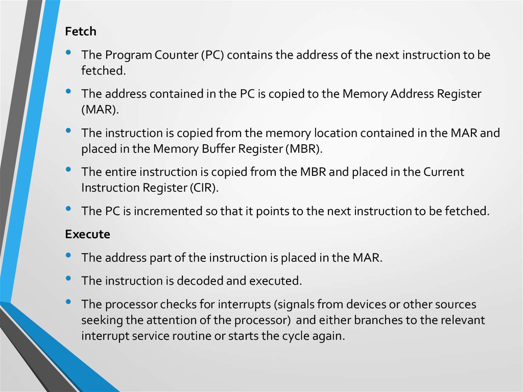
FetchThe Program Counter (PC) contains the address of the next instruction to be
fetched.
The address contained in the PC is copied to the Memory Address Register
(MAR).
The instruction is copied from the memory location contained in the MAR and
placed in the Memory Buffer Register (MBR).
The entire instruction is copied from the MBR and placed in the Current
Instruction Register (CIR).
The PC is incremented so that it points to the next instruction to be fetched.
Execute
The address part of the instruction is placed in the MAR.
The instruction is decoded and executed.
The processor checks for interrupts (signals from devices or other sources
seeking the attention of the processor) and either branches to the relevant
interrupt service routine or starts the cycle again.
27.
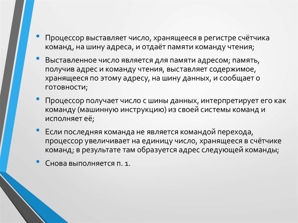
Процессор выставляет число, хранящееся в регистре счётчика
команд, на шину адреса, и отдаёт памяти команду чтения;
Выставленное число является для памяти адресом; память,
получив адрес и команду чтения, выставляет содержимое,
хранящееся по этому адресу, на шину данных, и сообщает о
готовности;
Процессор получает число с шины данных, интерпретирует его как
команду (машинную инструкцию) из своей системы команд и
исполняет её;
Если последняя команда не является командой перехода,
процессор увеличивает на единицу число, хранящееся в счётчике
команд; в результате там образуется адрес следующей команды;
Снова выполняется п. 1.
28. Процессор
• https://en.wikibooks.org/wiki/A-level_Computing/AQA/Computer_Components,_The_Stor
ed_Program_Concept_and_the_Internet/Machine_Level_
Architecture/Structure_and_role_of_the_processor
• https://en.wikibooks.org/wiki/IB/Group_4/Computer_Scien
ce/Computer_Organisation#von_Neumann_Architecture
• https://en.wikibooks.org/wiki/Alevel_Computing/AQA/Computer_Components,_The_Stored
_Program_Concept_and_the_Internet/Fundamental_Hardw
are_Elements_of_Computers/Boolean_identities