


 informatics
Similar presentations:


")


SOF108 - Computer Architecture Week 11: Memory Hierarchy
1. SOF108 - Computer Architecture Week 11: Memory Hierarchy
MALAYSIASOF108 - Computer Architecture
Week 11: Memory Hierarchy
1
2. Outline
• Fundamentals of Memory Technology• Why Memory Hierarchy?
• Cache Memory
• Cache Mapping Functions
2
3. Overview
• Computer memory exhibits perhaps the widest range of type, technology,organization, performance, and cost of any feature of a computer system
• No single technology is optimal in satisfying the memory requirements for
a computer system
• As a consequence, the typical memory system is equipped with a hierarchy
of memory subsystems
• Some internal to the system (we will mainly look into this one’s)
• Some external to the system
3
4. Overview of Storage System
• Key characteristics of computer memory system:• Location
• Capacity
• Access method
• Physical type
• Physical characteristics
* See Appendix for more details
4
5. An expanded view of the memory system
56. Memory Performance Gap
Why we need memory hierarchy?100,000
Performance
10,000
1,000
Processor-Memory
Performance Gap
Growing
Processor
100
10
Memory
1
1980
1985
1990
1995
2000
2005
2010
Year
Memory Performance Gap
6
7. Memory Hierarchy
• The total memory capacity of a computer can be visualized as hierarchy ofcomponents.
• Auxiliary/secondary memory – Slow but high capacity
• Main memory – Relatively faster than secondary memory, but comparatively smaller
capacity
• Cache memory – Fast memory, but….
• The overall goal of Memory Hierarchy:
• to obtain the highest possible average access speed while minimizing the total cost
of the entire memory system.
7
8.
StorageDisk drives
RAM
Cache
9.
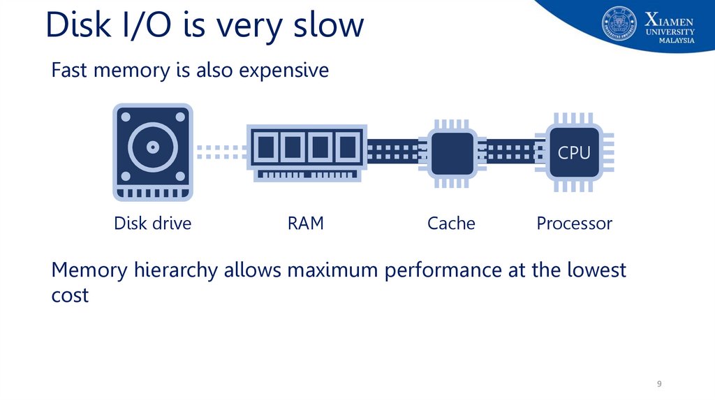
Disk I/O is very slowFast memory is also expensive
CPU
Disk drive
RAM
Cache
Processor
Memory hierarchy allows maximum performance at the lowest
cost
9
10. Location
• Processor (CPU) Local Memory• registers (e.g. PC, IR etc.)
• Internal / Primary Memory
• main memory (RAM)
• cache
• External / Secondary Memory
• Peripheral storage devices e.g. disk (e.g. floppy, hard disk, CD, DVD etc.), tape
accessible via I/O controllers.
10
11. Capacity
• Internal / Main memory• Typically expressed in term of bytes (1 byte=8 bits).
• Typical in the range of Gigabyte (GB)
• External memory
• Typically expressed in term of bytes.
• Typical in the range of GB to Terabyte (TB).
11
12. Access Methods
Sequential accessDirect access
Random access
Memory is organized into units
of data called records
Involves a shared read-write
mechanism
Each addressable location in
memory has a unique, physically
wired-in addressing mechanism
Access must be made in a
specific linear sequence
Individual blocks or records have
a unique address based on
physical location
The time to access a given
location is independent of the
sequence of prior accesses and is
constant
Access time is variable
Access time is variable
Any location can be selected at
random and directly addressed
and accessed
Main memory and some cache
systems are random access
12
13. Access Methods
• Sequential access (e.g. tapes)• Memory is organized into units of data called records - access must be made in a
specific linear sequence. The access time is highly variable.
• Direct access (e.g. disks)
• Individual blocks or records have a unique address based on physical location.
• Access accomplished by direct access to reach the general vicinity plus sequential.
• Access time is variable
• Random access (e.g. main memory)
• Each addressable location (word or byte) in memory has a unique, physically wired-in
addressing mechanism. Access time is constant.
13
14. Physical Types
• Semiconductor memory• Magnetic surface memory – used for disk and tape
• Optical
• Magneto-optical
14
15. Physical Characteristics
• Volatile• Information decays naturally when electrical power is switched off - semiconductor
memory. (e.g. main memory)
• Non-volatile memory
• Information remains after power switched off unless deliberately changed - magnetic
surface, optical and semiconductor memories. E.g.: magnetic surface memory (e.g.
hard disk, floppy, flash drive, CD-RW, DVD etc.)
• Non-erasable memory
• Information cannot be altered, except by destroying the storage unit.
• Semiconductor of this type is known as read-only memory (ROM).
15
16. Memory Hierarchy
• Programmers want unlimited amounts of memory with low latency to storeunlimited programs.
• Fast memory technology is more expensive per bit than slower memory
• Solution: organize memory system into a memory hierarchy
• Entire addressable memory space available in largest, slowest memory
• Each level maps addresses from slower, larger memory to faster, smaller
• Incrementally smaller and faster memories, each containing a subset of the memory below it,
proceed in steps up toward the processor
16
17. Memory Hierarchy
1718.
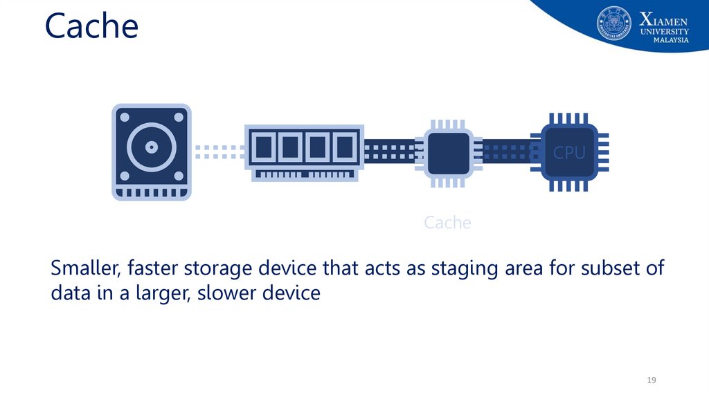
CacheCPU
Cache
Cache is typically integrated directly into CPU chip or placed on a
separate chip that has a separate bus interconnect with the CPU
18
19.
CacheCPU
Cache
Smaller, faster storage device that acts as staging area for subset of
data in a larger, slower device
19
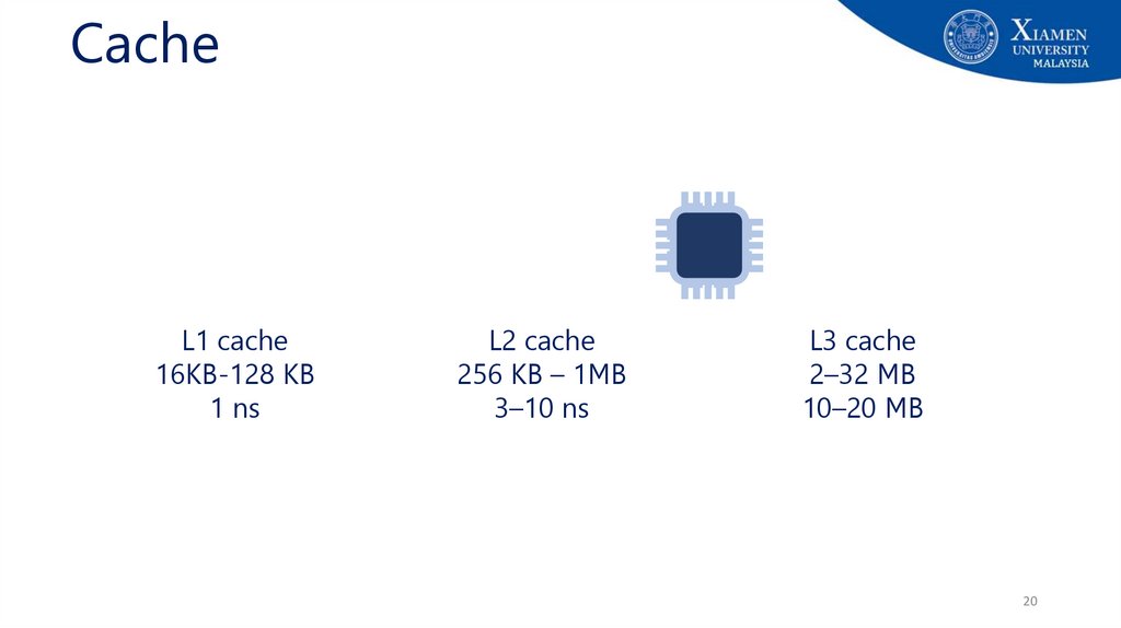
20.
CacheL1 cache
16KB-128 KB
1 ns
L2 cache
256 KB – 1MB
3–10 ns
L3 cache
2–32 MB
10–20 MB
20
21.
CacheCPU
CPU
CPU
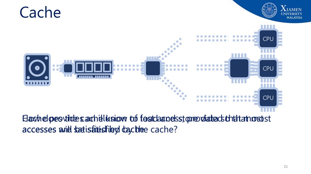
Cachedoes
provides
an illusion
provided
that
most
How
the cache
know of
to fast
loadaccess,
and store
data so
that
most
are satisfied
by cache
accesses will
be satisfied
by the cache?
21
22. Principle of locality
• Principle of locality / Locality of references: Program access arelatively small portion of the address space at any instant of time
• Example: 90/10 rule: "A program spends 90% of its time in 10% of its code"
• Implication: we can predict with reasonable accuracy what
instructions and data a program will use in the near future based on
its accesses in the recent past.
22
23. Principle of Locality
• When the computer uses something, it will probably use it again verysoon, and it will probably use the "neighbors" of this item very soon.
• There are two basic types of reference locality – temporal and spatial
locality.
• Temporal locality: states that recently accessed items are likely to be
accessed in the near future.
• Spatial locality: says that items whose addresses are near one another tend
to be referenced close together in time.
23
24. How do memory hierarchies work?
• Fundamental idea of a memory hierarchy:• For each k, the faster, smaller device at level k serves as cache for larger, slower
device at level k+1
• How do memory hierarchies work?
• Programs tend to access data at level k more often than they access data at level
k+1
• Thus, storage at level k+1 can be slower, and thus larger and cheaper per bit
• Net effect: Large pool of memory that costs as little as the cheap storage near the
bottom, but that serves data to programs at ≈ rate of the fast storage near the top.
24
25. Cache Memory
• Cache: Smaller, faster storage device that acts as staging area for subsetof data in a larger, slower device (RAM)
• Basic concept for Cache:
• higher levels are smaller and faster
• maintain copies of data from lower levels
• provide illusion of fast access to larger storage, provided that most accesses are
satisfied by cache
• work if memory accesses exhibit good locality of references
• Analogy: Think it something like a refrigerator
25
26. Cache Operation
1.2.
3.
4.
CPU requests contents of memory location
Check cache for this data (level k)
If present (a hit), get from cache (fast)
When a word is not found in the cache, a
miss occurs:
a) Fetch word from lower level (higher cache level,
e.g. k+1) in hierarchy, incur higher latency
b) Lower level may be another cache or the main
memory
c) Place block into cache
5. Then deliver from cache to CPU
26
27.
Cache OperationLevel k:
Level k+1:
48
3
Smaller, faster, more expensive
device at level k caches a
subset of the blocks from level k+1
9
14
10
10
4
Data is copied between
levels in block-sized transfer units
0
1
2
3
4
5
6
7
8
9
10
11
12
13
14
15
Larger, slower, cheaper storage
device at level k+1 is partitioned
into blocks.
27
28. Basic Cache Design
• Cache only holds a portion of a program• Which part of the program does the cache
contain?
• Most recently accessed references
• Cache is divided into units called cache blocks
(also known as cache lines), each block holds
contiguous set of memory addresses
• How does the CPU know which part of the
program the cache is holding?
• Each cache block has extra bits, called cache tag,
which hold the main memory address of the data
in the block
28
29. Cache Example
2930. Cache Example
3031. Cache Example
3132. Cache Example
3233. Cache Example
3334. Cache Example
3435. Cache Example
3536. Cache Example
3637. Cache Example
3738. Cache Example
3839. Cache Example
3940. Cache Example
4041. Cache Example
4142. Cache Example
4243. Cache Example
4344. No Cache vs Cache
4445. Elements of Cache Design
• Cache Placement Policy / Mapping function: Where can a block be placed in theupper level?
• direct, fully associative, set associative
• Replacement policy: Which block should be replaced on a miss?
• least-recently used, first-in-first-out, least-frequently used, random
• Write policy : What happens on a write?
• write through, write back, write once
• Number of caches: How many caches?
• single- or two-level, unified or split
45
46. Cache and Main Memory Structure
• Main memory• Memory size: 2n addressable words (n-bit
address)
• Block size: K words (Word length: x bits)
• Number of blocks: M = 2n / K
• Cache
• Number of lines: C (C << M)
• Number of memory blocks much larger than the
number of cache lines
• Note: Tag is used to identify a block
46
47. Cache Structure: TAG
• A cache line contains two fields• Data from RAM
• The address of the block currently in the cache.
• TAG field: the part of the cache line that stores the address of the
block
• Many different addresses can be in any given cache line. The tag field
specifies the address currently in the cache line
47
48. Cache Lines
• The cache memory is divided into blocks or lines.• Currently lines can range from 16 to 64 bytes
• Data is copied to and from the cache one line at a time
• The lower log2(line size) bits of a memory address specify a particular
byte in a line
48
49. Cache Lines: Example
• With a line size of 4, the offset is: log 2 4 = 2 bits• The lower 2 bits specify which byte in the line
49
50. Cache Mapping Function
• Which memory blocks are allowed into which cache lines?• Direct mapped (block can go to only one line)
• Associative / Fully Associative (block can go to any line)
• Set-associative (block can go to one of N lines)
Direct
• The simplest technique
• Maps each block of main memory into only
one possible cache line
Associative
• Permits each main memory block to be
loaded into any line of the cache
• The cache control logic interprets a
memory address simply as a Tag and a
Word field
Set Associative
• A compromise that exhibits the strengths
of both the direct and associative
approaches while reducing their
disadvantages
• To determine whether a block is in the
cache, the cache control logic must
simultaneously examine every line’s Tag for
a match
50
51. Cache Mapping: Direct
• Each location (address) in RAM has one specific place in cache wherethe data will be held
• Since a data block from RAM can only be in one specific line in the
cache, it must always replace the one block that was already there.
• Map each block of main memory into only one possible cache line.
• Which cache line: (Block number) mod (Number of lines)
51
52. Direct Mapping: Address Structure
• Offset/word: The lower log2(line size) bits define which byte in the block• Line: The next log2(number of lines) bits defines which line of the cache
• Tag: The remaining upper bits are the tag field
***The bits in the tag field and the line field define the block number
52
53. Direct Mapping
Advantage:• By looking at the physical character, you can easily
look at the line in the cache and check if the data is
available.
Disadvantage:
• Because of the labelling, there’s a restriction on the
placement
• E.g: Block 0 has to be placed in only line 0, not in
another slots even though they are free
overhead.
54. Direct Mapping: Address Structure
• Memory address is interpreted as tag, line and offset*• Address length = tag + line + offset = (s + w) bits
• Total number of addressable memory units = 2s+w words or bytes
• Depending on word addressable or byte addressable memory
• Block size = line size = 2w words or bytes
• Number of blocks in main memory = 2s+w/2w = 2s = 2t+l
• Number of lines in cache = m = 2l
s
Tag, s-l
Line, l
offset, w
*words or bytes – Depending on whether it is word addressable memory or byte addressable memory
54
55. A Hypothetical Direct Mapping
Memory• 8-bit memory address
• One memory address
contain 1-byte of data
• Let’s assume 1 word is equal
to 1 byte
Where in the cache does the
content of memory address
0b00000000 maps to?
• L0 (line 0)
56. Direct Addressing: Example
6Direct Addressing: Example
• 32 bit addresses (can address 4 GB)
• 32 KB of cache, 64 byte lines
• Bits to specify offset?
• offset is 6 bits
• Number of lines?
• 32 KB / 64 = 512
• Bits to specify which line?
• log2(512) = 9
• Bits to specify Tag?
• 32-(9+6)
57. Direct Mapping: Example Address
7Direct
Mapping:
Example
Address
• Using the previous direct mapping scheme with 17 bit tag, 9 bit index/line and 6 bit offset
01111101011101110001101100111000
• Compare the tag field of line 001101100 (10810) for the value 01111101011101110. If it
matches, return byte 111000 (5610) of the line
*Index here is referring to the line number (for direct mapping)
58. Cache Mapping: Fully Associative
8Cache Mapping: Fully Associative
• In associative cache mapping, the data from any location in RAM can be
stored in any location in cache
• When the processor wants an address, all tag fields in the cache are checked
to determine if the data is already in the cache
• Each tag line requires circuitry to compare the desired address with the tag
field
• All tag fields are checked in parallel
59. Fully Associative Mapping: Address Structure
9Fully Associative Mapping: Address Structure
• Offset/word: The lower log2(line size) bits define which byte in the
block
• Tag: The remaining upper bits are the tag field.
***The bits in the tag field define the block number
60. Fully Associative Mapping: Address Structure
Memory address is interpreted as tag and offset* (word or byte)• Address length = (s + w) bits
• Number of addressable units = 2s+w words or bytes
• Block size = line size = 2w words or bytes
• Number of blocks in main memory = 2s+w/2w = 2s
• Number of lines in cache = undetermined / not relevant
Tag, s
offset, w
*words or bytes – Depending on whether it is word addressable memory or byte addressable memory
61. A Hypothetical Fully Associative Mapping
1A Hypothetical Fully Associative Mapping
Memory
• 8-bit memory address
• One memory address contain
1-byte of data
• Let’s assume 1 word is equal to
1 byte
Where in the cache does the
content of memory address
0b00000000 maps to?
Can map to any cache lines, i.e.,
L0, L1, L2, L3 (check which line
is empty, if all the lines are
full need a replacement policy)
62. Fully Associative Mapping: Example
2Fully Associative Mapping: Example
• For a 4 GB address space with 128 KB cache and 32 byte blocks:
• How many bits to specify the offset/word?
• log232 = 5 bits
• How many bits to specify the tag?
• 32-5 = 27 bits
63. Fully Associative Mapping: Example Address
3Fully Associative Mapping: Example Address
• Using the previous associate mapping scheme with 27 bit tag and 5 bit
offset
01111101011101110001101100111000
• Compare all tag fields for the value 011111010111011100011011001. If a
match is found, return byte 11000 (2410) of the line
64. Cache Mapping: Set Associative
4Cache Mapping: Set Associative
• Set: The cache lines are grouped into sets
• The data can be stored in any of the lines in the set
• When the processor wants an address, it indexes to the set and then searches the
tag fields of all lines in the set for the desired address
• Example: 2 way set associative mapping: A given block can be in one of 2 lines in only one set
• Map each block of main memory into only one possible cache set.
• Which cache set: (Block number) mod (Number of sets)
65. Set Associative Mapping: Address Structure
5Set Associative Mapping: Address Structure
• Set: Identifies the set
• Offset/word: The lower log2(line size) bits define which byte in the
block
• Tag: The remaining upper bits are the tag field
***The bits in the tag field and the set field define the block number
66. Set Associative Mapping: Address Structure
6Set Associative Mapping: Address Structure
• Address length = (s + w) bits
• Total number of addressable units = 2s+w
• Block size = line size = 2w
• Number of blocks in main memory = 2s
• Number of lines in set = k
• Number of sets = v = 2d
• Number of lines in cache = kv = k X 2d
s
Tag, s-d
Set, d
offset, w
67. A Hypothetical Set Associative Mapping
7A Hypothetical Set Associative Mapping
Memory
• 8-bit memory address
• One memory address
contain 1-byte of data
• Let’s assume 1 word is equal
to 1 byte
Where in the cache does the
content of memory address
0b00000000 maps to?
• Set 0 (can map to either
L0 or L1 in S0)
68. Set Associative Mapping: Example
8Set Associative Mapping: Example
• 32 bit addresses
• 32 KB of cache, 64 byte lines, 4 way set associative
• Bits to specify offset?
• log2(64) = 6 bits
• Number of lines?
• 32 KB / 64 = 512
• Number of sets?
• 512 / 4 = 128
• Bits to specify set?
• log2(128) = 7
• Bits to specify tag?
• 32-(7+6) = 19 bits
69. Set Associative Mapping: Example
9Set Associative Mapping: Example
• Using the previous set-associate mapping with 19 bit tag, 7 bit index/ set and 6 bit offset
01111101011101110001101100111000
• Compare the tag fields in all four lines of set 1101100 for the value 0111110101110111000. If a
match is found, return byte 111000 (5610) of that line
*Index here is referring to the set number (for set associative mapping)
70. Advantages and Disadvantages of Direct Mapping
• Advantages:• Simple
• Inexpensive
• Disadvantage:
• Fixed location for given block - If a program accesses 2 blocks that map to the
same line repeatedly, cache misses are very high (low hit ratio)
70
71. Advantages and Disadvantages of Fully Associative Mapping
• Advantage:• Flexibility in replacing a block (on a line) when a new block is read into the
cache
• Disadvantage:
• Complex circuitry required to examine the tags of all cache lines in parallel.
• Expensive.
71
72. Why Set Associative?
2Why Set Associative?
• Advantage: Normally 2-way or 4-way improve hit ratio
73. Summary
3Summary
• Memory hierarchy is an organizational approach to improve the
performance of the computer
• Different types of Cache addressing
• Each have their own trade-offs
74. End of Lecture 8!
End of Lecture 8!• Additional readings:
• Chapter 4 (Cache Memory)
• Stallings, W. Computer organization and architecture: Designing for performance, Tenth Edition Upper Saddle River, N.J: Prentice
Hall.
• Chapter 2 (Memory Hierarchy Design)
• John L. Hennessy and David Patterson, Computer Architecture: A Quantitative Approach, Fourth Edition, Morgan Kaufham.
• Appendix B (Review of Memory Hierarchy)
• John L. Hennessy and David Patterson, Computer Architecture: A Quantitative Approach, Fourth Edition, Morgan Kaufham.
• Acknowledgement:
• Some of the animations (Slides 8 to 13) used in this presentation were prepared by 2018/09 batch students: Kenneth Tan, Tuan Hong
Chua, Jiahao Liu, Chenxi Xiong, ZiXi Hee for their SOF108 class presentation
• Next lecture:
• Number of Cache,Cache replacement policy, Cache write policy, Cache performance metrics, Virtual memory (maybe)
• Announcements:
Mid-semester exam will be scheduled on Week 10 (20th Nov. 2023)
Topics covered: Lecture 1 – 7 (Chapter 1.1 – Chapter 3.3)
• Questions?
74
75.
Appendix: Additional Self Readings75
76.
Appendix: University's vision and missionVision
Xiamen University Malaysia aspires to become a university with a
distinct global outlook, featuring first-class teaching and research, and
embracing cultural diversity.
Mission
To nurture young talents with dignity and wisdom, turning them into
fine citizens of the region who will contribute to the prosperity of the
people and social progress of Malaysia, China and Southeast Asia.
76
77. Advantages and Disadvantages of Direct Mapping
• Advantages:• Simple
• Inexpensive
• Disadvantage:
• Fixed location for given block - If a program accesses 2 blocks that map to the
same line repeatedly, cache misses are very high (low hit ratio)
77
78. Advantages and Disadvantages of Fully Associative Mapping
• Advantage:• Flexibility in replacing a block (on a line) when a new block is read into the
cache
• Disadvantage:
• Complex circuitry required to examine the tags of all cache lines in parallel.
• Expensive.
78