


 software
Similar presentations:


![[P970]Download Tool Guide ExternalMode Ver 1.2 2011.02.21](https://cf.ppt-online.org/files/thumb/r/rTZwRbhcf50UvF4YSJP876iosWmACteOKnay3d.jpg "[P970]Download Tool Guide ExternalMode Ver 1.2 2011.02.21")


3.2 Service Tools
1.
2.
Top secretSecret
Internal use only
Public
VRV IV+
Service Product Training
Level 3 Service Technician – Troubleshooting & Repair
3.
4. Service Tools3
Troubleshooting & Repair - Internal use only
4.
4. Service ToolsA. Overview
B. Service Checker Type 3
C. D-Checker
D. Mobile Monitoring Tool
E. Inverter Analyzer
F. Groupwork
5.
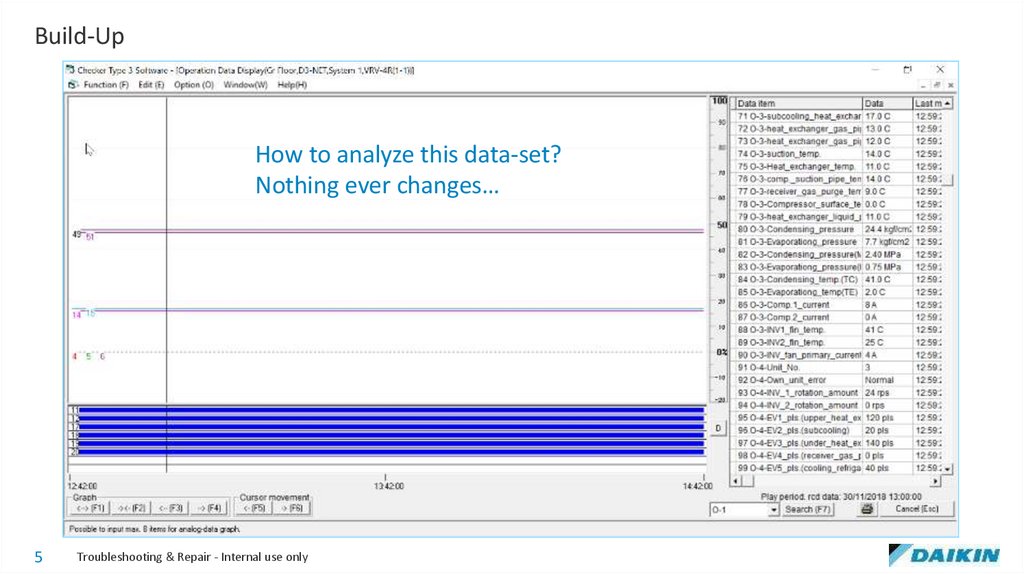
Build-UpHow to analyze this data-set?
Nothing ever changes…
5
Troubleshooting & Repair - Internal use only
6.
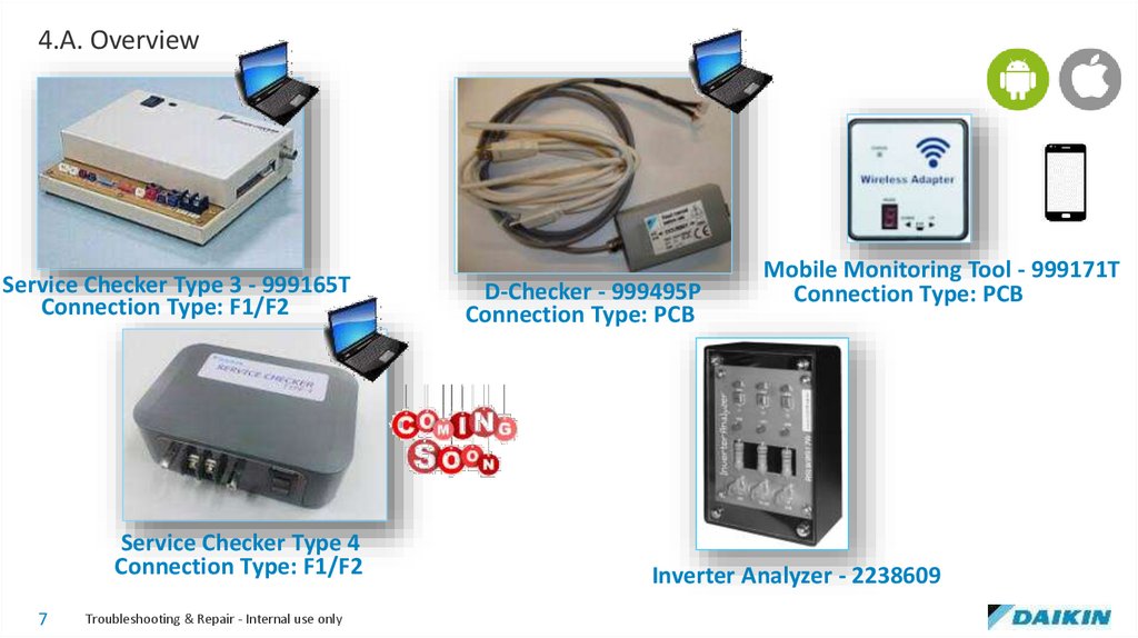
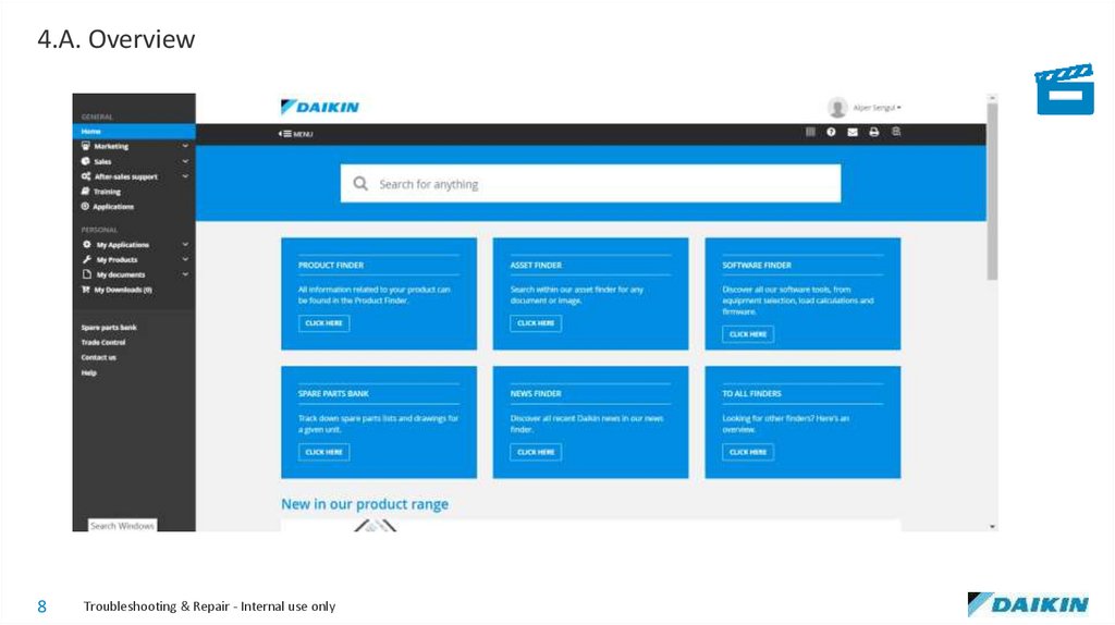
4.A. Overview6
Troubleshooting & Repair - Internal use only
7.
4.A. OverviewService Checker Type 3 - 999165T
Connection Type: F1/F2
Service Checker Type 4
Connection Type: F1/F2
7
Troubleshooting & Repair - Internal use only
D-Checker - 999495P
Connection Type: PCB
Mobile Monitoring Tool - 999171T
Connection Type: PCB
Inverter Analyzer - 2238609
8.
4.A. Overview8
Troubleshooting & Repair - Internal use only
9.
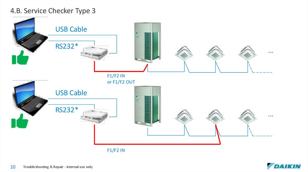
4.B. Service Checker Type 39
Troubleshooting & Repair - Internal use only
10.
4.B. Service Checker Type 3USB Cable
RS232*
…
F1/F2 IN
or F1/F2 OUT
USB Cable
RS232*
…
F1/F2 IN
10
Troubleshooting & Repair - Internal use only
11.
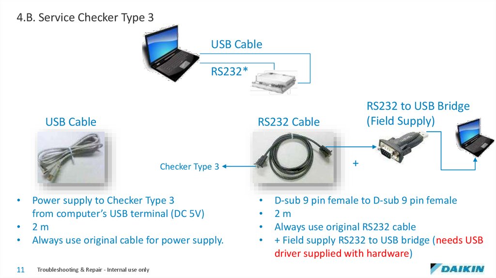
4.B. Service Checker Type 3USB Cable
RS232*
USB Cable
RS232 Cable
+
Checker Type 3
11
Power supply to Checker Type 3
from computer’s USB terminal (DC 5V)
2m
Always use original cable for power supply.
Troubleshooting & Repair - Internal use only
RS232 to USB Bridge
(Field Supply)
D-sub 9 pin female to D-sub 9 pin female
2m
Always use original RS232 cable
+ Field supply RS232 to USB bridge (needs USB
driver supplied with hardware)
12.
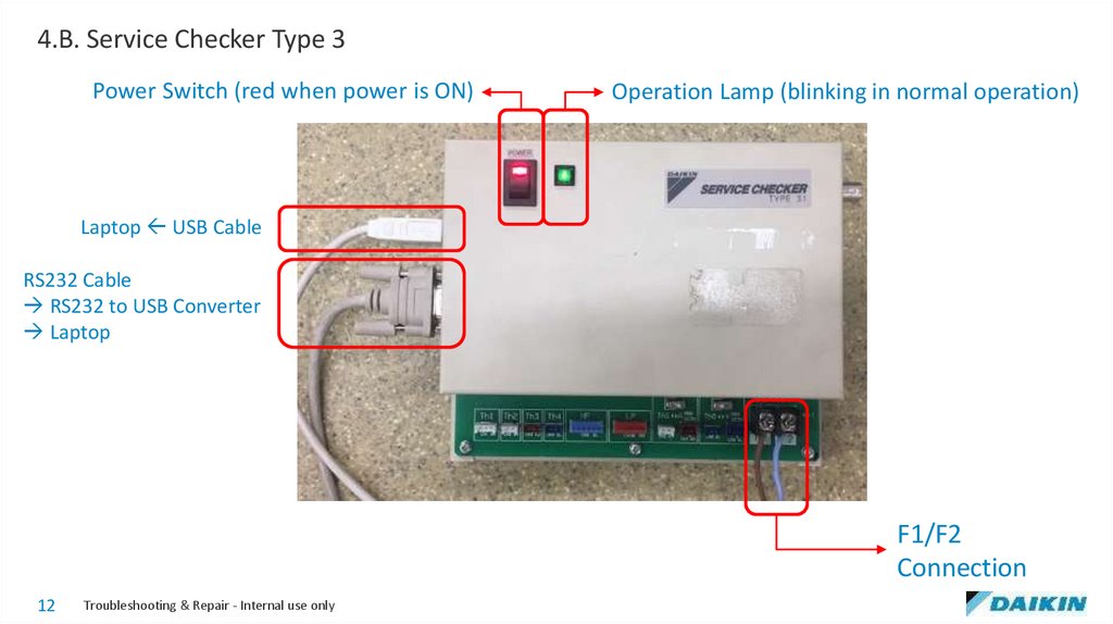
4.B. Service Checker Type 3Power Switch (red when power is ON)
Operation Lamp (blinking in normal operation)
Laptop USB Cable
RS232 Cable
RS232 to USB Converter
Laptop
F1/F2
Connection
12
Troubleshooting & Repair - Internal use only
13.
4.B. Service Checker Type 313
Troubleshooting & Repair - Internal use only
14.
4.B. Service Checker Type 314
Troubleshooting & Repair - Internal use only
15.
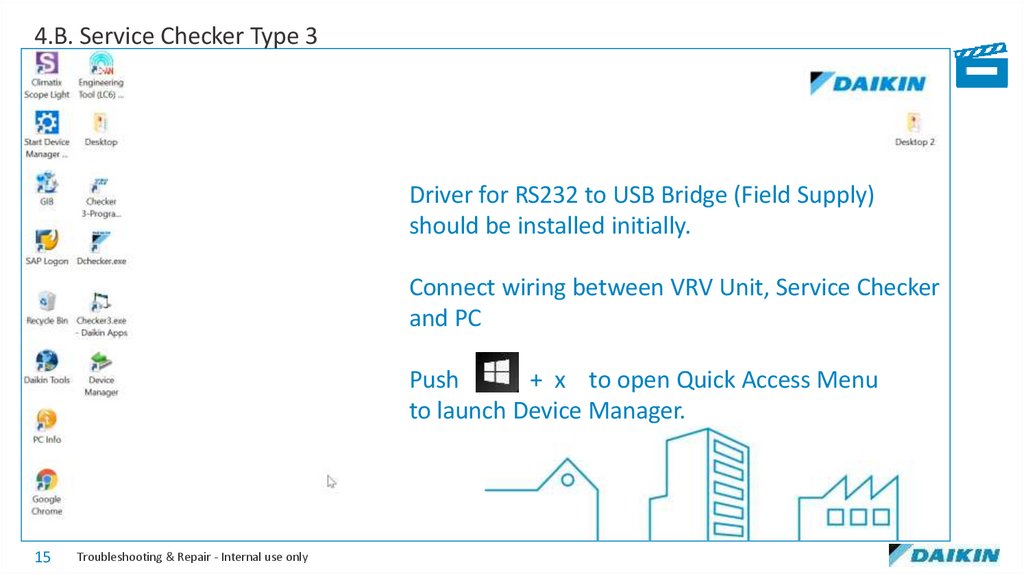
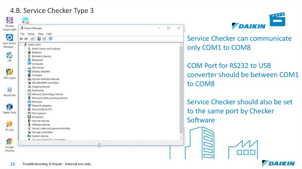
4.B. Service Checker Type 3Driver for RS232 to USB Bridge (Field Supply)
should be installed initially.
Connect wiring between VRV Unit, Service Checker
and PC
Push
+ x to open Quick Access Menu
to launch Device Manager.
15
Troubleshooting & Repair - Internal use only
16.
4.B. Service Checker Type 3Service Checker can communicate
only COM1 to COM8
COM Port for RS232 to USB
converter should be between COM1
to COM8
Service Checker should also be set
to the same port by Checker
Software
16
Troubleshooting & Repair - Internal use only
17.
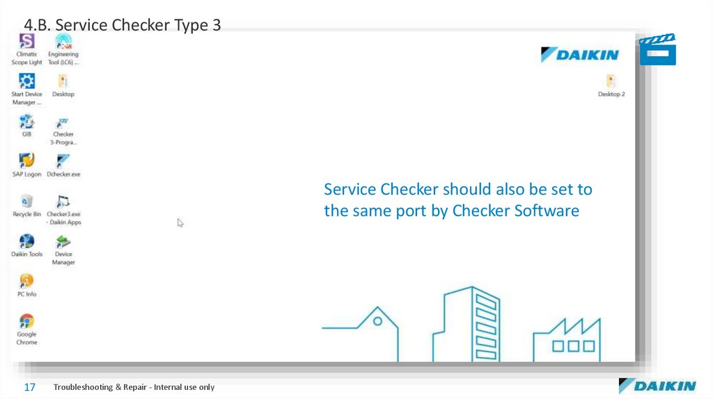
4.B. Service Checker Type 3Service Checker should also be set to
the same port by Checker Software
17
Troubleshooting & Repair - Internal use only
18.
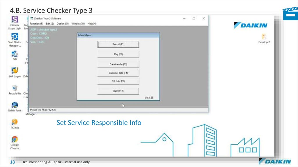
4.B. Service Checker Type 3Set Service Responsible Info
18
Troubleshooting & Repair - Internal use only
19.
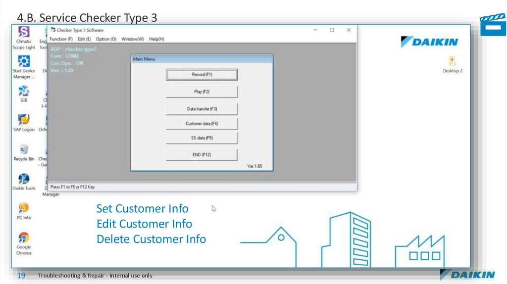
4.B. Service Checker Type 3Set Customer Info
Edit Customer Info
Delete Customer Info
19
Troubleshooting & Repair - Internal use only
20.
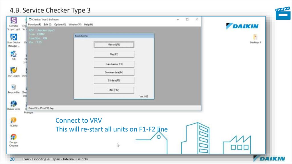
4.B. Service Checker Type 3Connect to VRV
This will re-start all units on F1-F2 line
20
Troubleshooting & Repair - Internal use only
21.
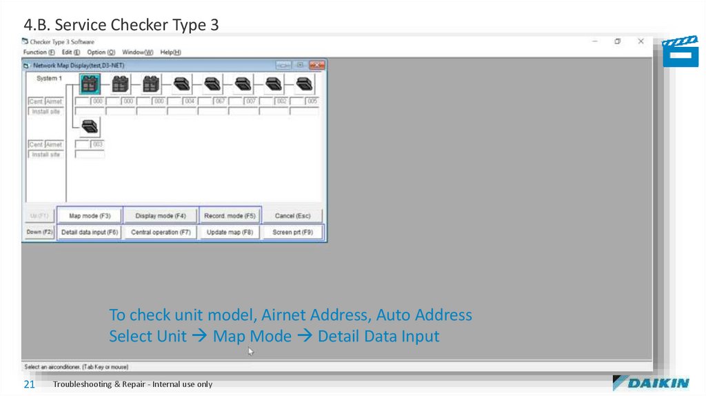
4.B. Service Checker Type 3To check unit model, Airnet Address, Auto Address
Select Unit Map Mode Detail Data Input
21
Troubleshooting & Repair - Internal use only
22.
4.B. Service Checker Type 3If group addresses are present, to check addresses and to control the unit:
Map Mode Central Operation
22
Troubleshooting & Repair - Internal use only
23.
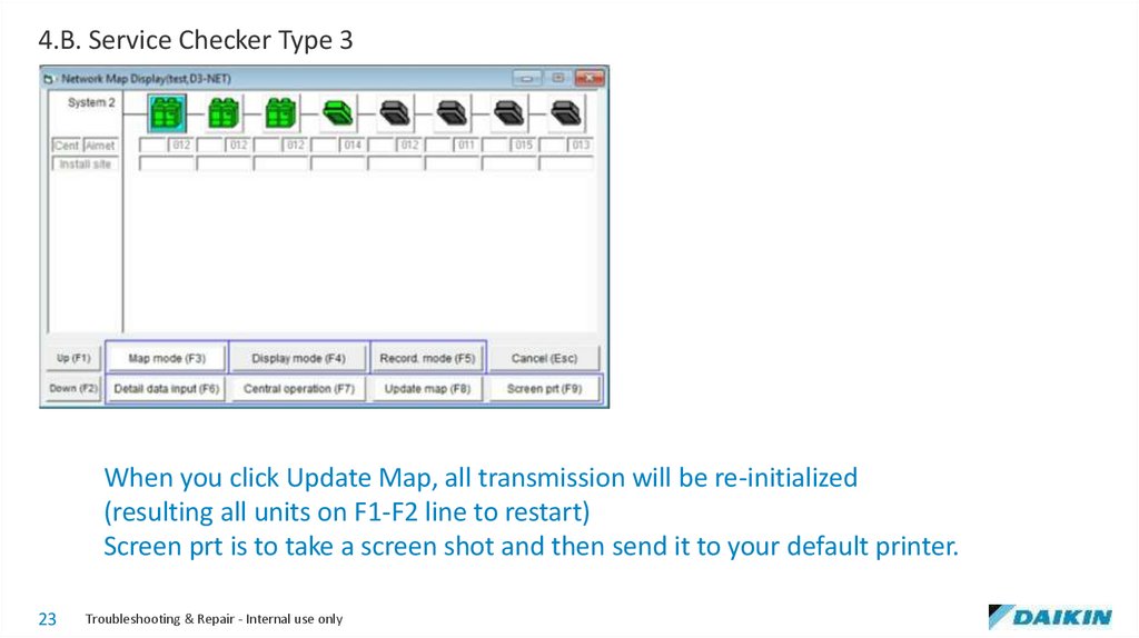
4.B. Service Checker Type 3When you click Update Map, all transmission will be re-initialized
(resulting all units on F1-F2 line to restart)
Screen prt is to take a screen shot and then send it to your default printer.
23
Troubleshooting & Repair - Internal use only
24.
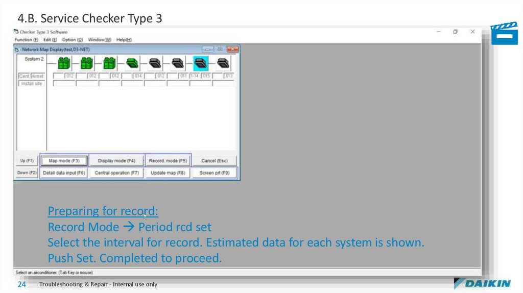
4.B. Service Checker Type 3Preparing for record:
Record Mode Period rcd set
Select the interval for record. Estimated data for each system is shown.
Push Set. Completed to proceed.
24
Troubleshooting & Repair - Internal use only
25.
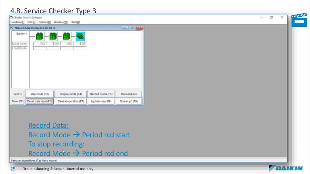
4.B. Service Checker Type 3Record Data:
Record Mode Period rcd start
To stop recording:
Record Mode Period rcd end
25
Troubleshooting & Repair - Internal use only
26.
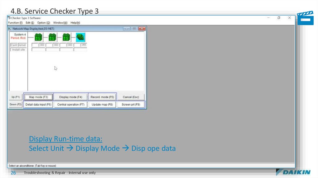
4.B. Service Checker Type 3Display Run-time data:
Select Unit Display Mode Disp ope data
26
Troubleshooting & Repair - Internal use only
27.
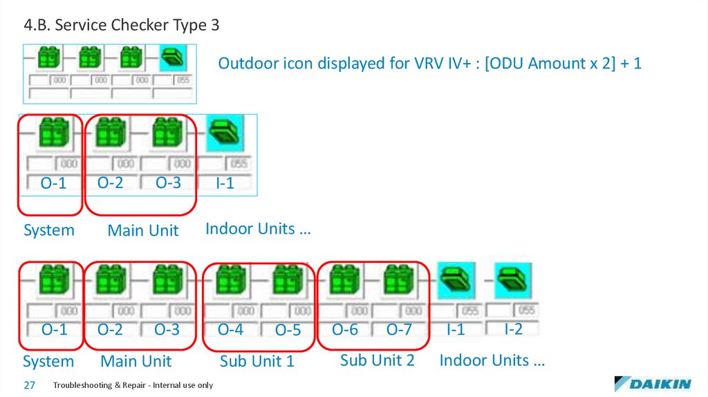
4.B. Service Checker Type 3Outdoor icon displayed for VRV IV+ : [ODU Amount x 2] + 1
O-1
System
O-1
System
27
O-2
O-3
I-1
Main Unit
Indoor Units …
O-2
O-4
O-3
Main Unit
Troubleshooting & Repair - Internal use only
O-5
Sub Unit 1
O-6
O-7
Sub Unit 2
I-1
I-2
Indoor Units …
28.
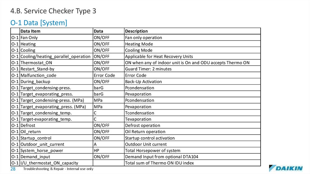
4.B. Service Checker Type 3O-1 Data [System]
Data Item
Data
O-1 Fan Only
ON/OFF
O-1 Heating
ON/OFF
O-1 Cooling
ON/OFF
O-1 Cooling/heating_parallel_operation ON/OFF
O-1 Thermostat_ON
ON/OFF
O-1 Restart_Stand-by
ON/OFF
O-1 Malfunction_code
Error Code
O-1 During_backup
ON/OFF
O-1 Target_condensing-press.
barG
O-1 Target_evaporating_press.
barG
O-1 Target_condensing-press. (MPa)
MPa
O-1 Target_evaporating_press. (MPa)
MPa
O-1 Target_condensing_temp.
C
O-1 Target-evaporating_temp.
C
O-1 Defrost
ON/OFF
O-1 Oil_return
ON/OFF
O-1 Startup_control
ON/OFF
O-1 Outdoor_unit_current
A
O-1 System_horse_power
HP
O-1 Demand_input
ON/OFF
O-1 I/U_thermostat_ON_capacity
28
Troubleshooting & Repair - Internal use only
Description
Fan only operation
Heating Mode
Cooling Mode
Applicable for Heat Recovery Units
ON when any of indoor unit is On and ODU accepts Thermo ON
Guard Timer: 2 minutes
Error Code
Back-Up Activation
Pcondensation
Pevaporation
Pcondensation
Pevaporation
Tcondensation
Tevaporation
Defrost operation
Oil Return operation
Startup control activation
Outdoor Unit current
Total Horsepower of system
Demand Input from optional DTA104
Total sum of Thermo ON IDU index
29.
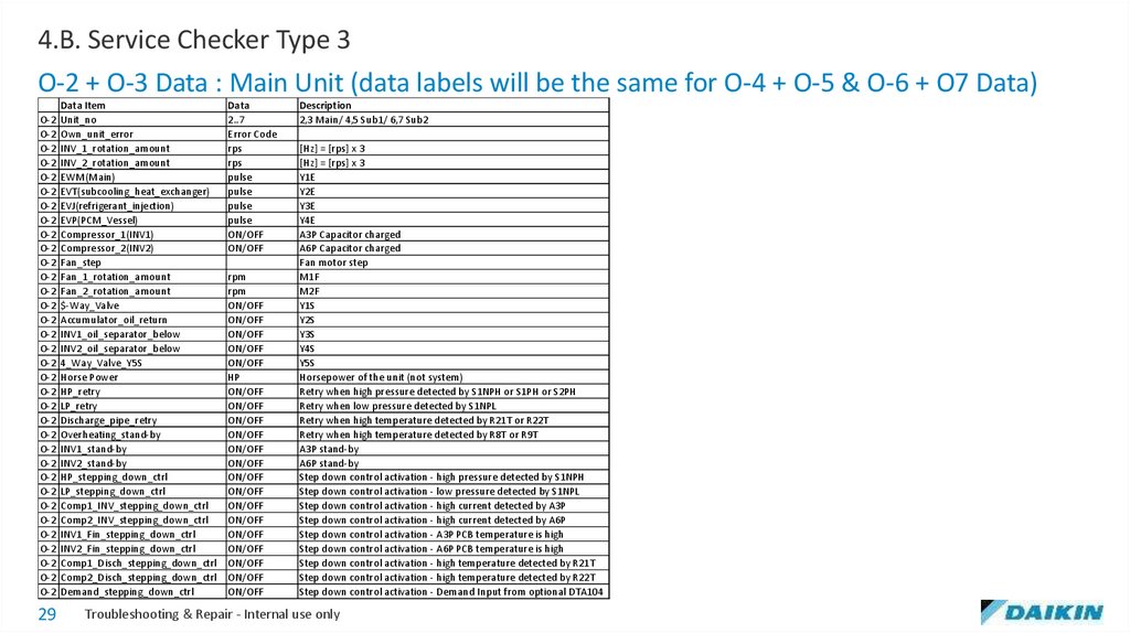
4.B. Service Checker Type 3O-2 + O-3 Data : Main Unit (data labels will be the same for O-4 + O-5 & O-6 + O7 Data)
Data Item
O-2 Unit_no
O-2 Own_unit_error
O-2 INV_1_rotation_amount
O-2 INV_2_rotation_amount
O-2 EWM(Main)
O-2 EVT(subcooling_heat_exchanger)
O-2 EVJ(refrigerant_injection)
O-2 EVP(PCM_Vessel)
O-2 Compressor_1(INV1)
O-2 Compressor_2(INV2)
O-2 Fan_step
O-2 Fan_1_rotation_amount
O-2 Fan_2_rotation_amount
O-2 $-Way_Valve
O-2 Accumulator_oil_return
O-2 INV1_oil_separator_below
O-2 INV2_oil_separator_below
O-2 4_Way_Valve_Y5S
O-2 Horse Power
O-2 HP_retry
O-2 LP_retry
O-2 Discharge_pipe_retry
O-2 Overheating_stand-by
O-2 INV1_stand-by
O-2 INV2_stand-by
O-2 HP_stepping_down_ctrl
O-2 LP_stepping_down_ctrl
O-2 Comp1_INV_stepping_down_ctrl
O-2 Comp2_INV_stepping_down_ctrl
O-2 INV1_Fin_stepping_down_ctrl
O-2 INV2_Fin_stepping_down_ctrl
O-2 Comp1_Disch_stepping_down_ctrl
O-2 Comp2_Disch_stepping_down_ctrl
O-2 Demand_stepping_down_ctrl
29
Data
2..7
Error Code
rps
rps
pulse
pulse
pulse
pulse
ON/OFF
ON/OFF
rpm
rpm
ON/OFF
ON/OFF
ON/OFF
ON/OFF
ON/OFF
HP
ON/OFF
ON/OFF
ON/OFF
ON/OFF
ON/OFF
ON/OFF
ON/OFF
ON/OFF
ON/OFF
ON/OFF
ON/OFF
ON/OFF
ON/OFF
ON/OFF
ON/OFF
Description
2,3 Main/ 4,5 Sub1/ 6,7 Sub2
[Hz] = [rps] x 3
[Hz] = [rps] x 3
Y1E
Y2E
Y3E
Y4E
A3P Capacitor charged
A6P Capacitor charged
Fan motor step
M1F
M2F
Y1S
Y2S
Y3S
Y4S
Y5S
Horsepower of the unit (not system)
Retry when high pressure detected by S1NPH or S1PH or S2PH
Retry when low pressure detected by S1NPL
Retry when high temperature detected by R21T or R22T
Retry when high temperature detected by R8T or R9T
A3P stand-by
A6P stand-by
Step down control activation - high pressure detected by S1NPH
Step down control activation - low pressure detected by S1NPL
Step down control activation - high current detected by A3P
Step down control activation - high current detected by A6P
Step down control activation - A3P PCB temperature is high
Step down control activation - A6P PCB temperature is high
Step down control activation - high temperature detected by R21T
Step down control activation - high temperature detected by R22T
Step down control activation - Demand Input from optional DTA104
Troubleshooting & Repair - Internal use only
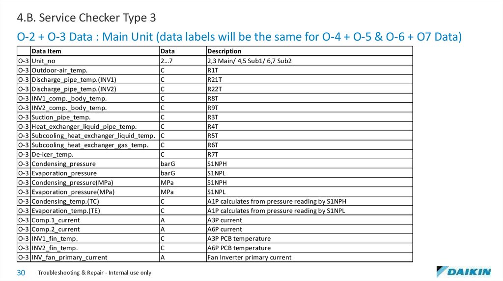
30.
4.B. Service Checker Type 3O-2 + O-3 Data : Main Unit (data labels will be the same for O-4 + O-5 & O-6 + O7 Data)
Data Item
O-3 Unit_no
O-3 Outdoor-air_temp.
O-3 Discharge_pipe_temp.(INV1)
O-3 Discharge_pipe_temp.(INV2)
O-3 INV1_comp._body_temp.
O-3 INV2_comp._body_temp.
O-3 Suction_pipe_temp.
O-3 Heat_exchanger_liquid_pipe_temp.
O-3 Subcooling_heat_exchanger_liquid_temp.
O-3 Subcooling_heat_exchanger_gas_temp.
O-3 De-icer_temp.
O-3 Condensing_pressure
O-3 Evaporation_pressure
O-3 Condensing_pressure(MPa)
O-3 Evaporation_pressure(MPa)
O-3 Condensing_temp.(TC)
O-3 Evaporation_temp.(TE)
O-3 Comp.1_current
O-3 Comp.2_current
O-3 INV1_fin_temp.
O-3 INV2_fin_temp.
O-3 INV_fan_primary_current
30
Troubleshooting & Repair - Internal use only
Data
2…7
C
C
C
C
C
C
C
C
C
C
barG
barG
MPa
MPa
C
C
A
A
C
C
A
Description
2,3 Main/ 4,5 Sub1/ 6,7 Sub2
R1T
R21T
R22T
R8T
R9T
R3T
R4T
R5T
R6T
R7T
S1NPH
S1NPL
S1NPH
S1NPL
A1P calculates from pressure reading by S1NPH
A1P calculates from pressure reading by S1NPL
A3P current
A6P current
A3P PCB temperature
A6P PCB temperature
Fan Inverter primary current
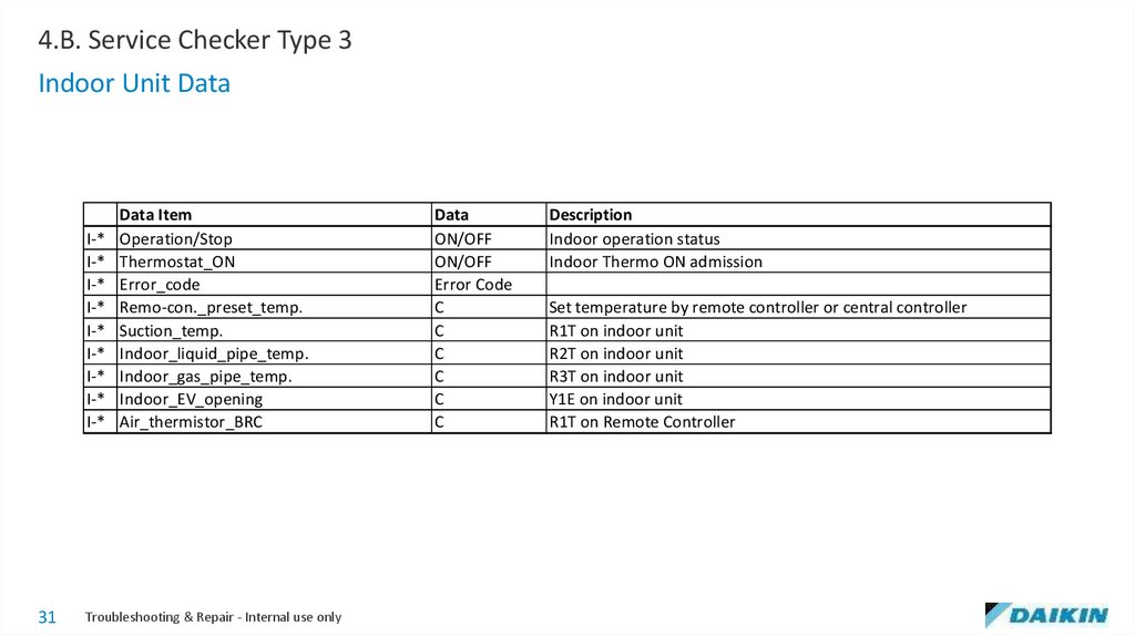
31.
4.B. Service Checker Type 3Indoor Unit Data
I-*
I-*
I-*
I-*
I-*
I-*
I-*
I-*
I-*
31
Data Item
Operation/Stop
Thermostat_ON
Error_code
Remo-con._preset_temp.
Suction_temp.
Indoor_liquid_pipe_temp.
Indoor_gas_pipe_temp.
Indoor_EV_opening
Air_thermistor_BRC
Troubleshooting & Repair - Internal use only
Data
ON/OFF
ON/OFF
Error Code
C
C
C
C
C
C
Description
Indoor operation status
Indoor Thermo ON admission
Set temperature by remote controller or central controller
R1T on indoor unit
R2T on indoor unit
R3T on indoor unit
Y1E on indoor unit
R1T on Remote Controller
32.
4.B. Service Checker Type 332
Troubleshooting & Repair - Internal use only
33.
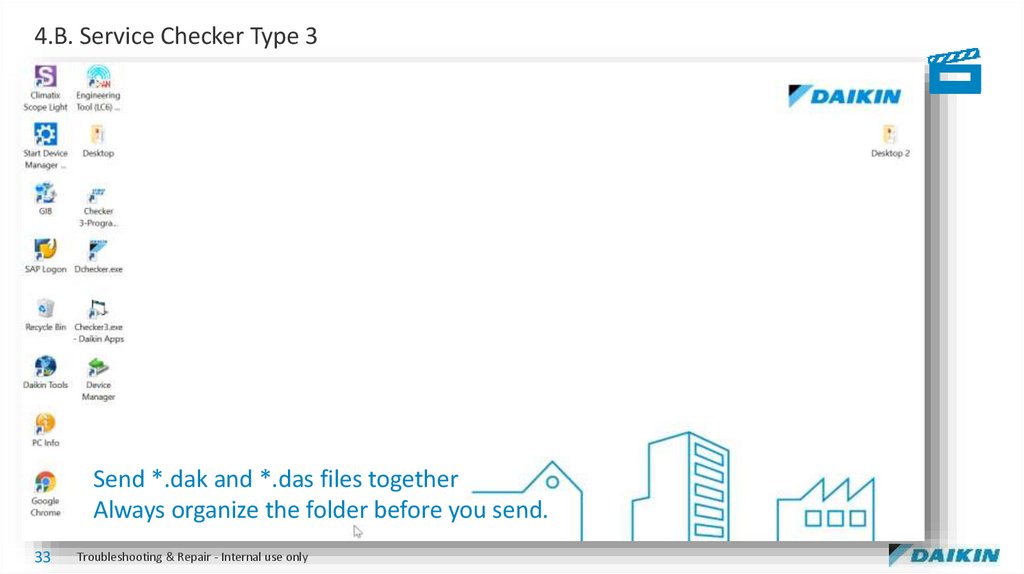
4.B. Service Checker Type 3Send *.dak and *.das files together
Always organize the folder before you send.
33
Troubleshooting & Repair - Internal use only
34.
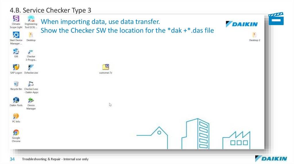
4.B. Service Checker Type 3When importing data, use data transfer.
Show the Checker SW the location for the *dak +*.das file
34
Troubleshooting & Repair - Internal use only
35.
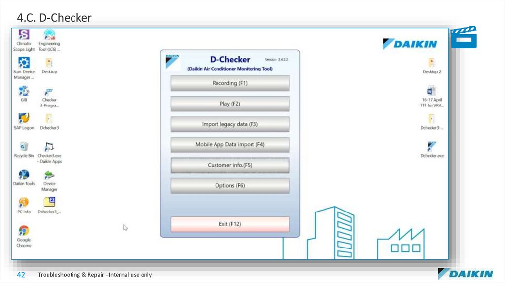
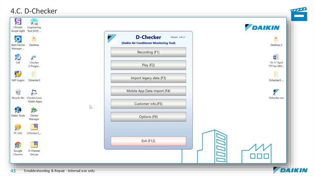
4.C. D-Checker35
Troubleshooting & Repair - Internal use only
36.
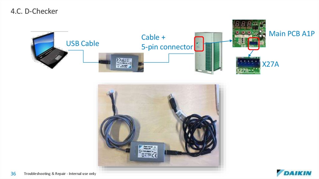
4.C. D-CheckerUSB Cable
Cable +
5-pin connector
Main PCB A1P
X27A
36
Troubleshooting & Repair - Internal use only
37.
4.C. D-Checker37
Troubleshooting & Repair - Internal use only
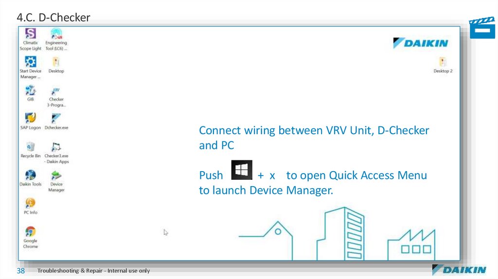
38.
4.C. D-CheckerConnect wiring between VRV Unit, D-Checker
and PC
Push
+ x to open Quick Access Menu
to launch Device Manager.
38
Troubleshooting & Repair - Internal use only
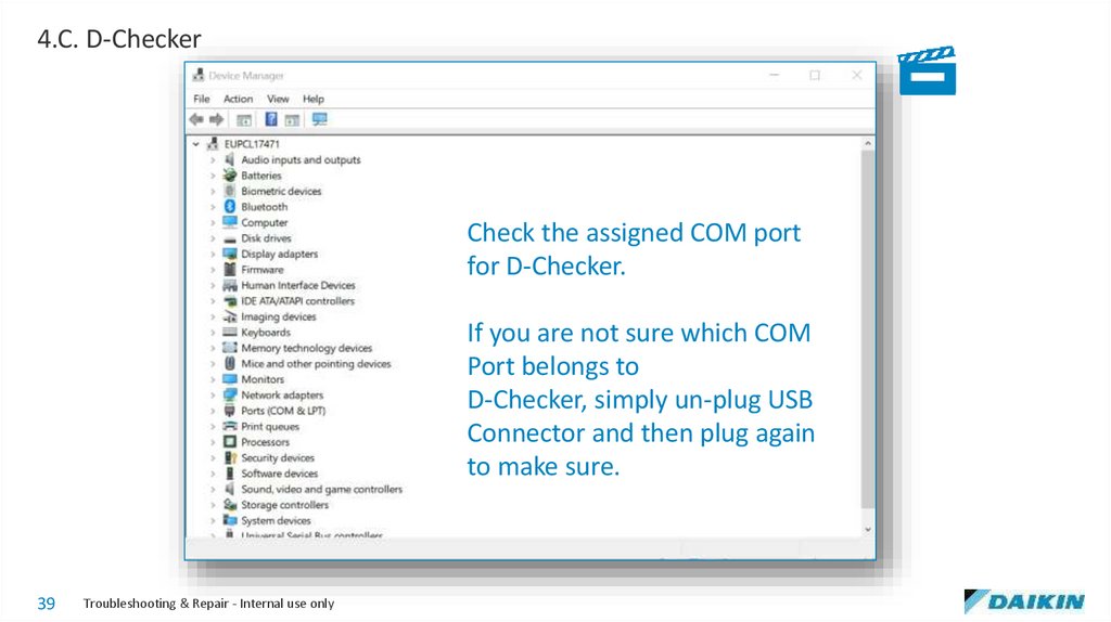
39.
4.C. D-CheckerCheck the assigned COM port
for D-Checker.
If you are not sure which COM
Port belongs to
D-Checker, simply un-plug USB
Connector and then plug again
to make sure.
39
Troubleshooting & Repair - Internal use only
40.
4.C. D-Checker40
Troubleshooting & Repair - Internal use only
41.
4.C. D-Checker41
Troubleshooting & Repair - Internal use only
42.
4.C. D-Checker42
Troubleshooting & Repair - Internal use only
43.
4.C. D-Checker43
Troubleshooting & Repair - Internal use only
44.
4.D. Mobile Monitoring Tool44
Troubleshooting & Repair - Internal use only
45.
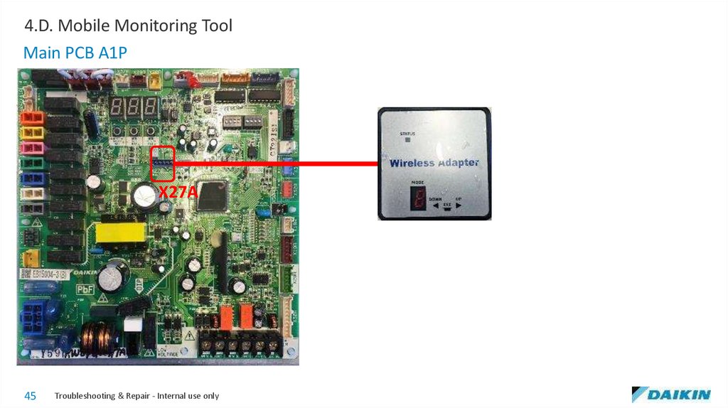
4.D. Mobile Monitoring ToolMain PCB A1P
X27A
45
Troubleshooting & Repair - Internal use only
46.
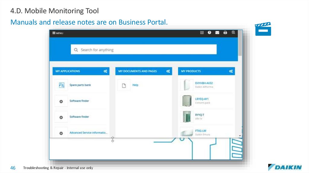
4.D. Mobile Monitoring ToolManuals and release notes are on Business Portal.
46
Troubleshooting & Repair - Internal use only
47.
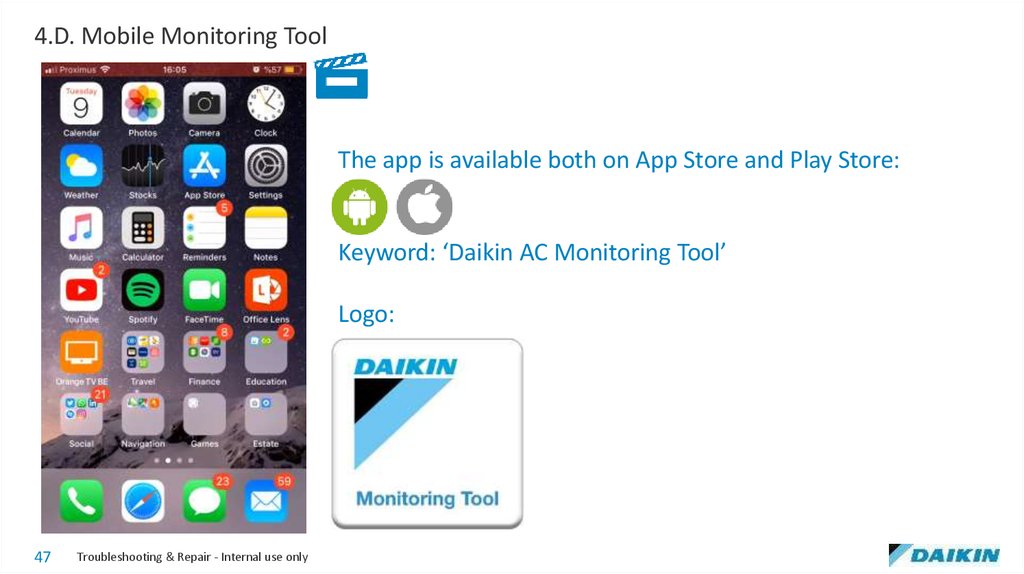
4.D. Mobile Monitoring ToolThe app is available both on App Store and Play Store:
Keyword: ‘Daikin AC Monitoring Tool’
Logo:
47
Troubleshooting & Repair - Internal use only
48.
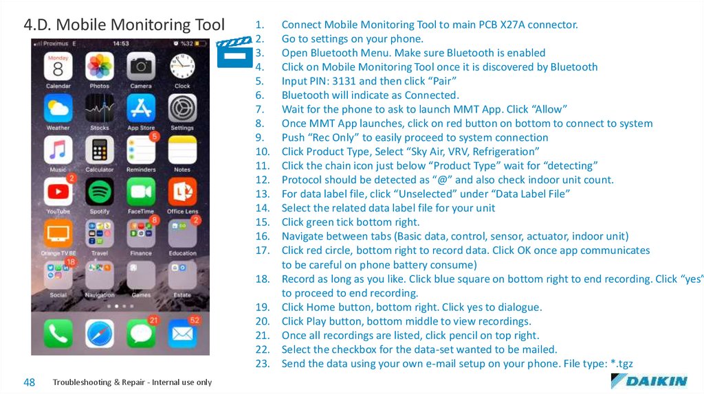
4.D. Mobile Monitoring Tool1.
2.
3.
4.
5.
6.
7.
8.
9.
10.
11.
12.
13.
14.
15.
16.
17.
18.
19.
20.
21.
22.
23.
48
Troubleshooting & Repair - Internal use only
Connect Mobile Monitoring Tool to main PCB X27A connector.
Go to settings on your phone.
Open Bluetooth Menu. Make sure Bluetooth is enabled
Click on Mobile Monitoring Tool once it is discovered by Bluetooth
Input PIN: 3131 and then click “Pair”
Bluetooth will indicate as Connected.
Wait for the phone to ask to launch MMT App. Click “Allow”
Once MMT App launches, click on red button on bottom to connect to system
Push “Rec Only” to easily proceed to system connection
Click Product Type, Select “Sky Air, VRV, Refrigeration”
Click the chain icon just below “Product Type” wait for “detecting”
Protocol should be detected as “@” and also check indoor unit count.
For data label file, click “Unselected” under “Data Label File”
Select the related data label file for your unit
Click green tick bottom right.
Navigate between tabs (Basic data, control, sensor, actuator, indoor unit)
Click red circle, bottom right to record data. Click OK once app communicates
to be careful on phone battery consume)
Record as long as you like. Click blue square on bottom right to end recording. Click “yes”
to proceed to end recording.
Click Home button, bottom right. Click yes to dialogue.
Click Play button, bottom middle to view recordings.
Once all recordings are listed, click pencil on top right.
Select the checkbox for the data-set wanted to be mailed.
Send the data using your own e-mail setup on your phone. File type: *.tgz
49.
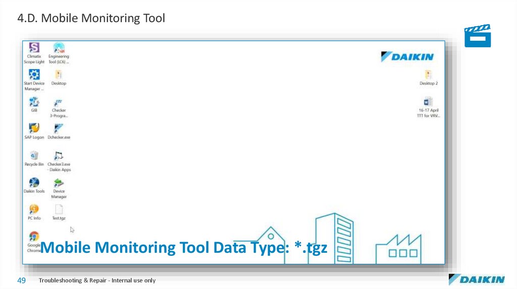
4.D. Mobile Monitoring ToolMobile Monitoring Tool Data Type: *.tgz
49
Troubleshooting & Repair - Internal use only
50.
4.E. Inverter Analyzer50
Troubleshooting & Repair - Internal use only
51.
4.E. Inverter AnalyzerInverter PCB
(A3P or A6P)
U V W
Part Code: 2238609
51
Troubleshooting & Repair - Internal use only
52.
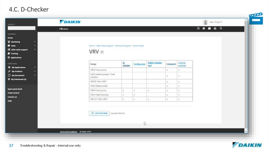
4.E. Inverter AnalyzerSee instruction movie on Business Portal: HERE
Or Go to Business Portal:
After Sales Support
Technical Support
Service Tools
VRV
Inverter Analyzer
Instruction Movie
52
Troubleshooting & Repair - Internal use only
53.
4.F. Groupwork53
Troubleshooting & Repair - Internal use only