


 industry
Similar presentations:


Visuals for Website Design
1.
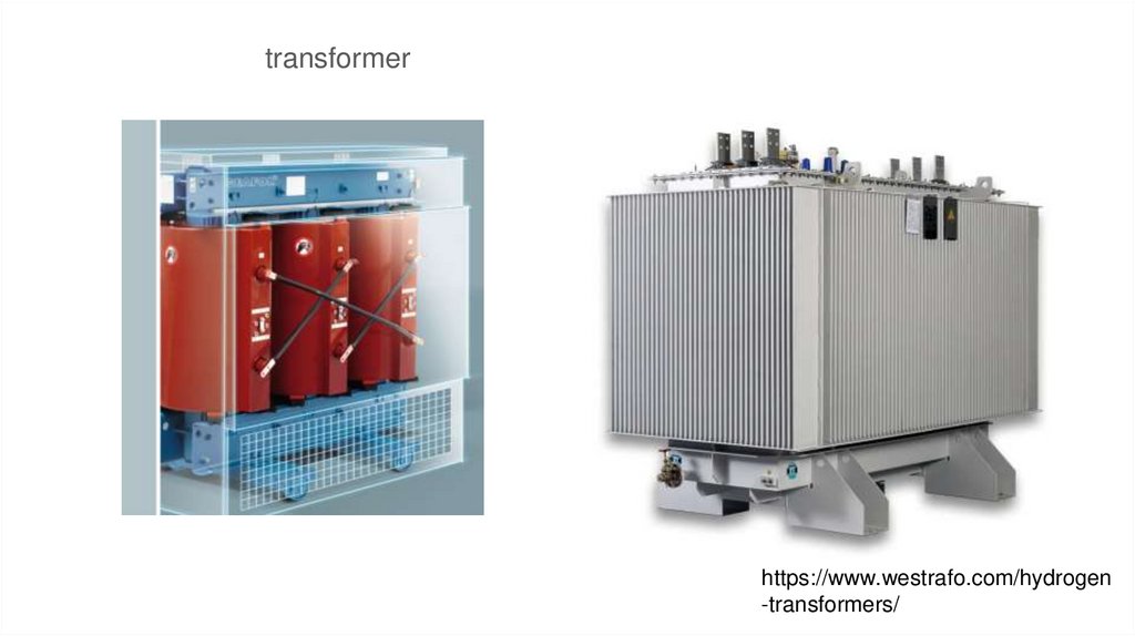
transformerhttps://www.westrafo.com/hydrogen
-transformers/
2.
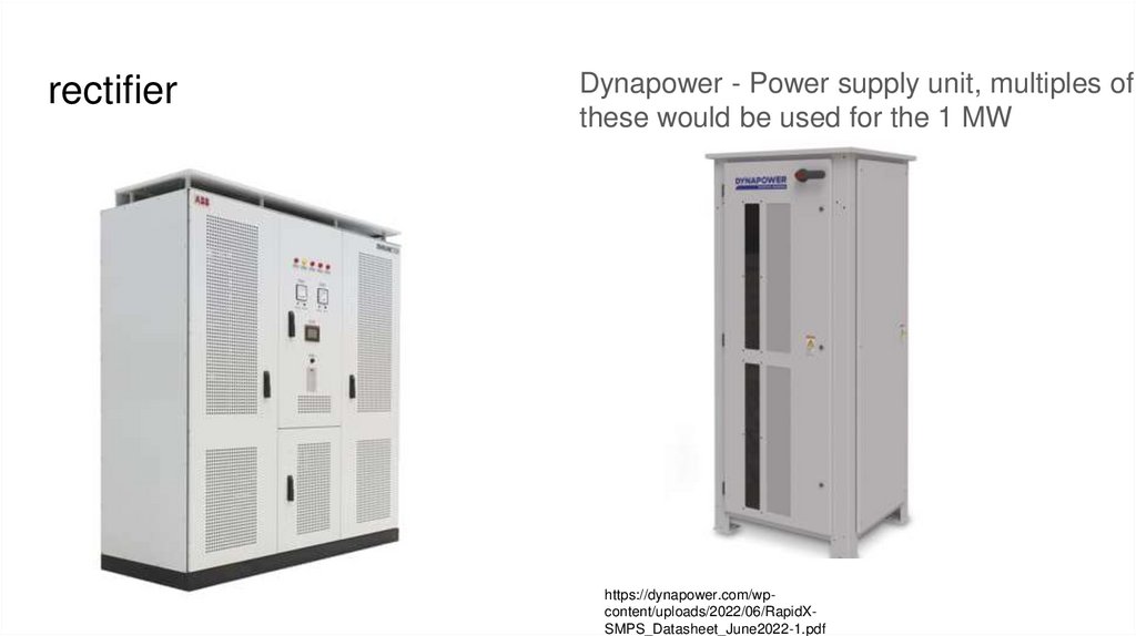
rectifierDynapower - Power supply unit, multiples of
these would be used for the 1 MW
https://dynapower.com/wpcontent/uploads/2022/06/RapidXSMPS_Datasheet_June2022-1.pdf
3.
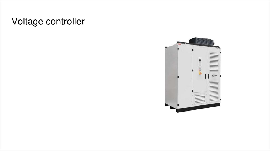
Voltage controller4.
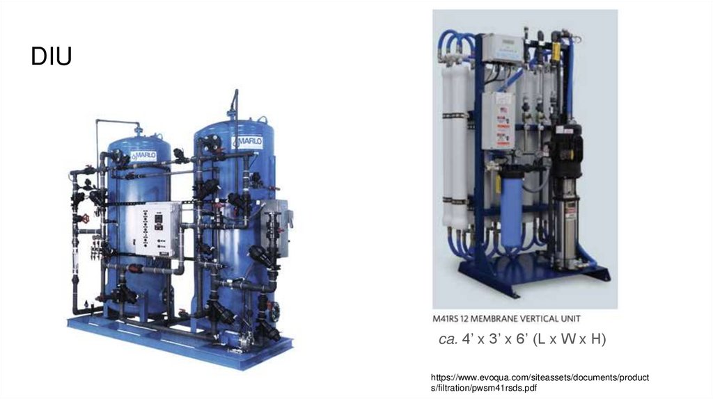
DIUca. 4’ x 3’ x 6’ (L x W x H)
https://www.evoqua.com/siteassets/documents/product
s/filtration/pwsm41rsds.pdf
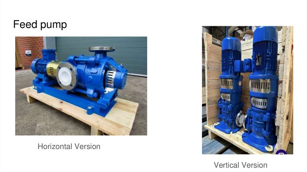
5.
Feed pumpHorizontal Version
Vertical Version
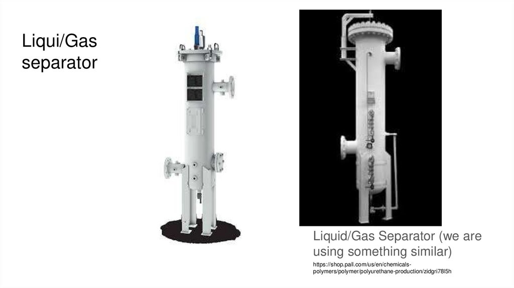
6.
Liqui/Gasseparator
Liquid/Gas Separator (we are
using something similar)
https://shop.pall.com/us/en/chemicalspolymers/polymer/polyurethane-production/zidgri78l5h
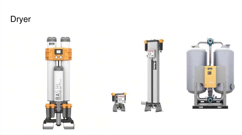
7.
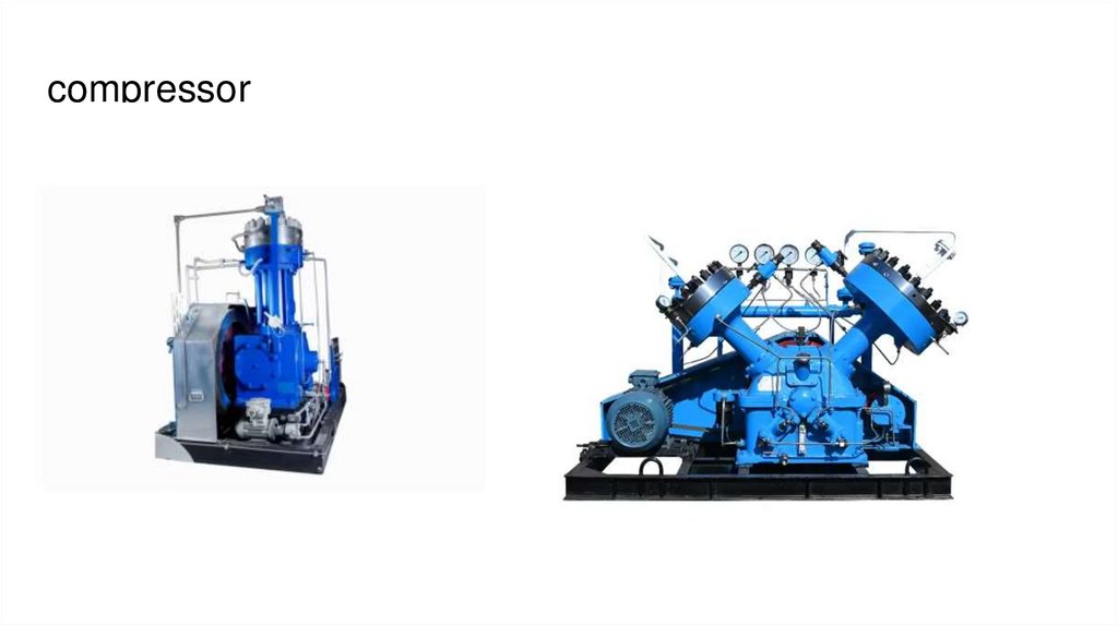
Dryer8.
compressor9.
Storage tanks10.
PLC11.
HMI12.
DATA LOGGER13.
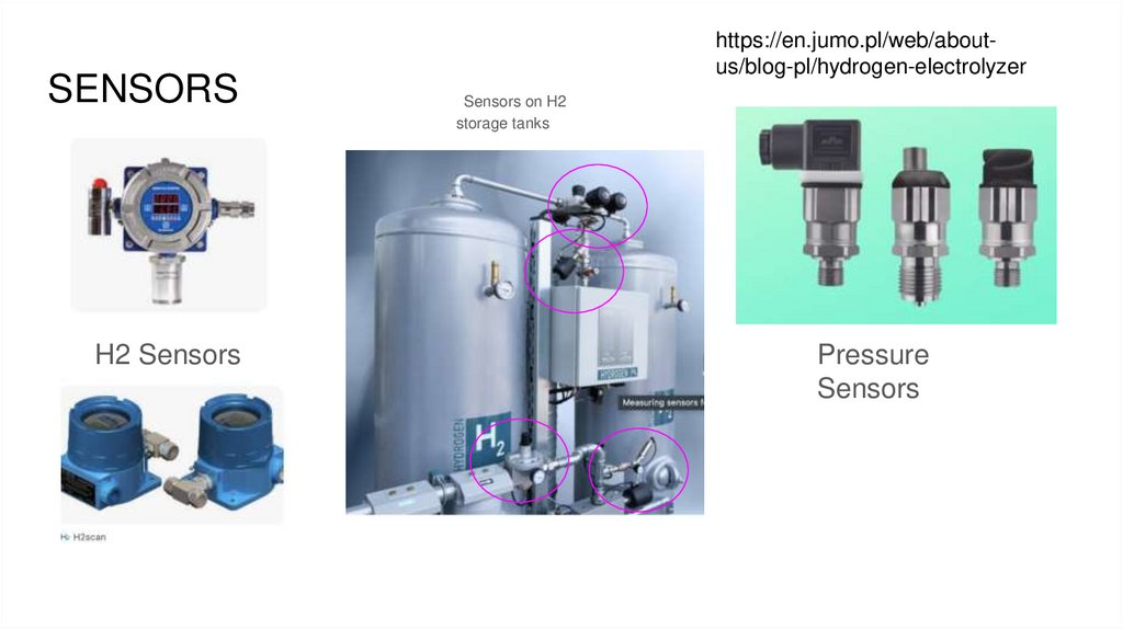
SENSORSH2 Sensors
https://en.jumo.pl/web/aboutus/blog-pl/hydrogen-electrolyzer
Sensors on H2
storage tanks
Pressure
Sensors
14.
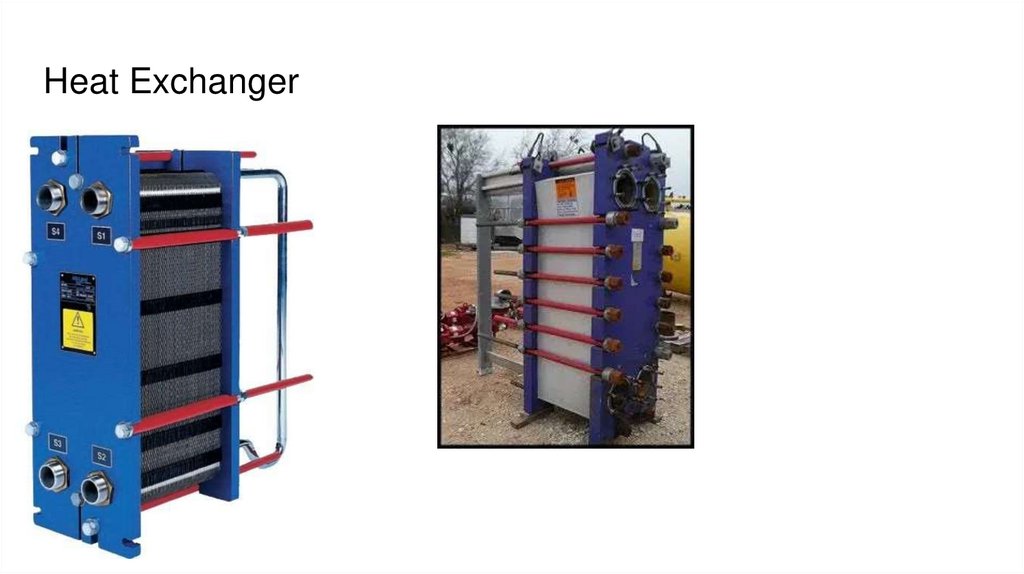
Heat Exchanger15.
Coolant Reservoir16.
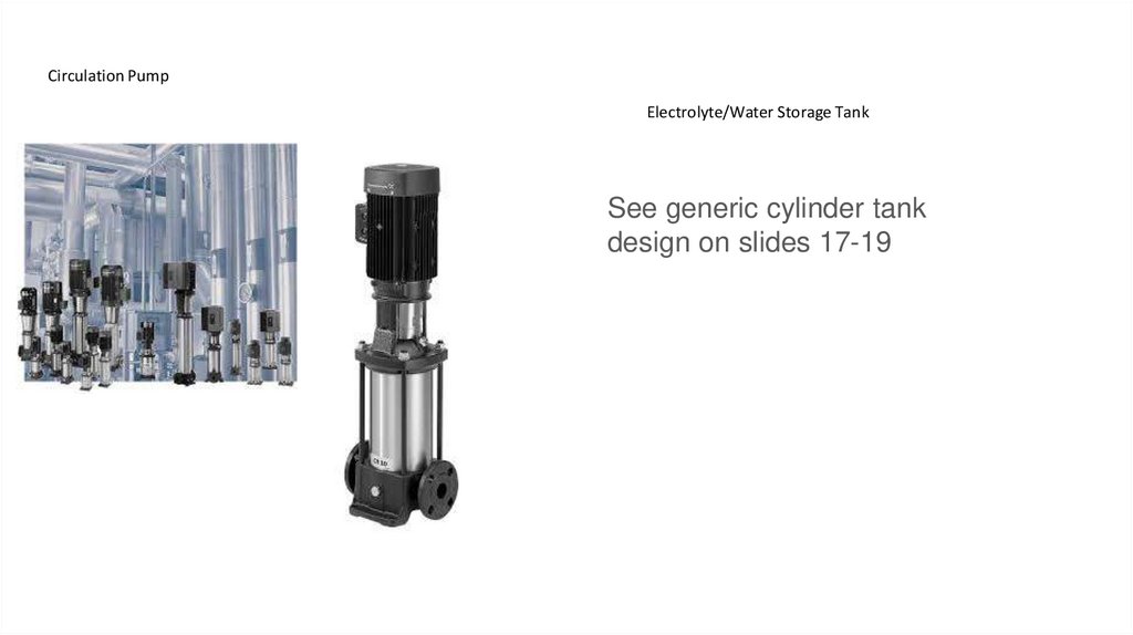
Circulation PumpElectrolyte/Water Storage Tank
See generic cylinder tank
design on slides 17-19
17.
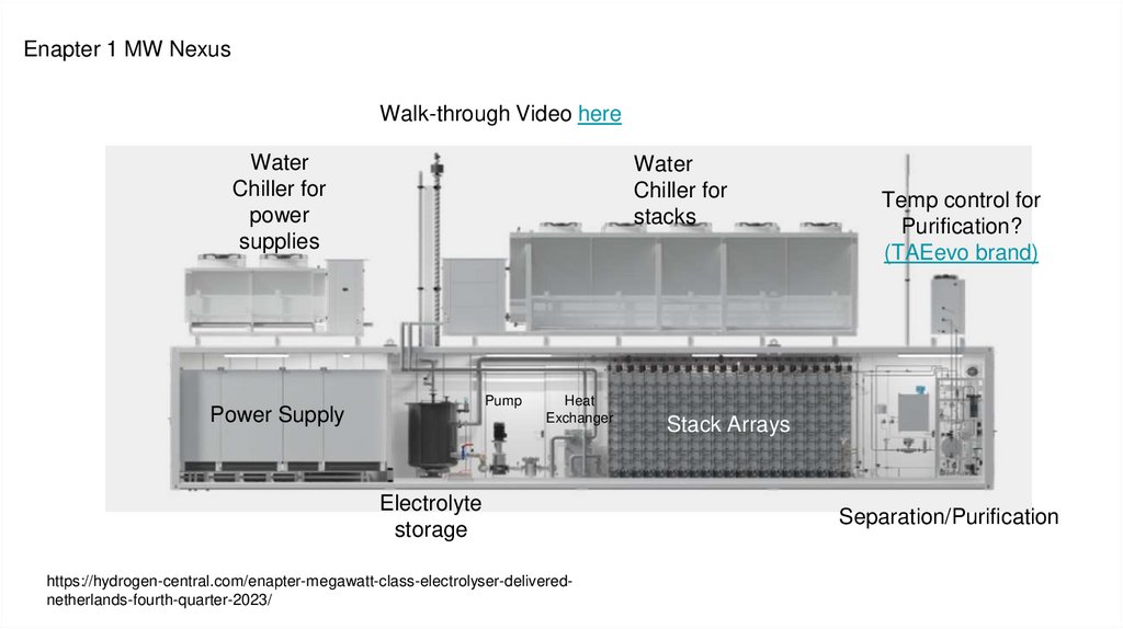
Enapter 1 MW NexusWalk-through Video here
Water
Chiller for
power
supplies
Water
Chiller for
stacks
Pump
Power Supply
Heat
Exchanger
Electrolyte
storage
https://hydrogen-central.com/enapter-megawatt-class-electrolyser-deliverednetherlands-fourth-quarter-2023/
Temp control for
Purification?
(TAEevo brand)
Stack Arrays
Separation/Purification
18.
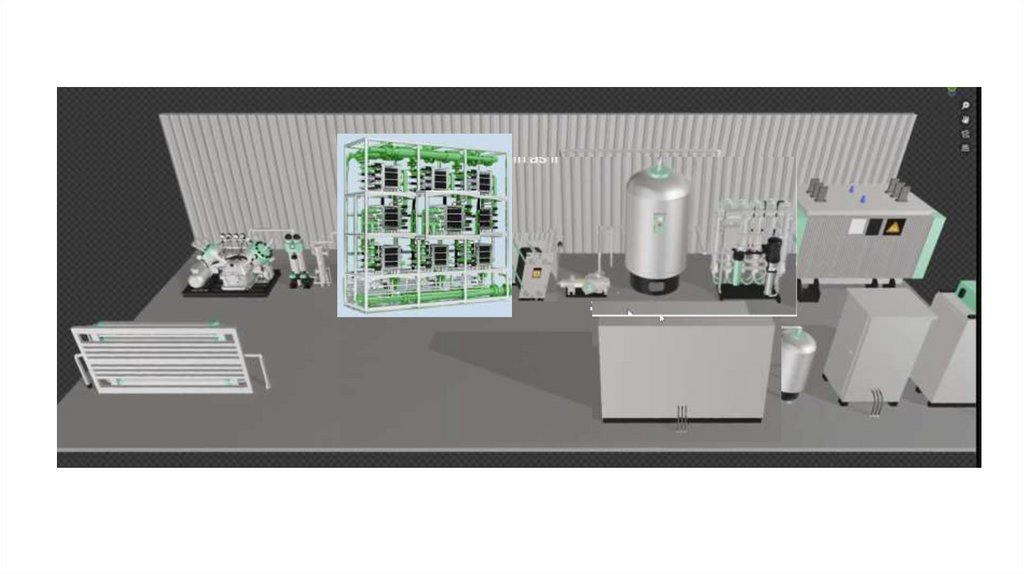
Enapter 1 MW Nexus19.
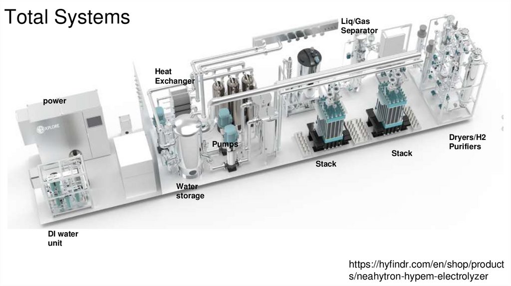
Total SystemsLiq/Gas
Separator
Heat
Exchanger
power
Pumps
Stack
Dryers/H2
Purifiers
Stack
Water
storage
DI water
unit
https://hyfindr.com/en/shop/product
s/neahytron-hypem-electrolyzer
20.
https://nelhydrogen.com/product/mc-series-electrolyser/#3d-model
21.
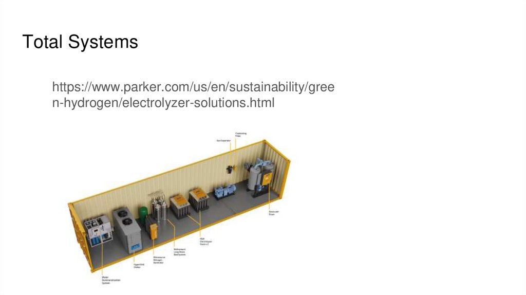
Total Systemshttps://www.parker.com/us/en/sustainability/gree
n-hydrogen/electrolyzer-solutions.html
22.
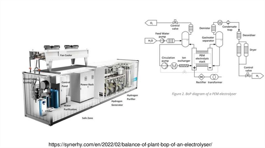
https://synerhy.com/en/2022/02/balance-of-plant-bop-of-an-electrolyser/23.
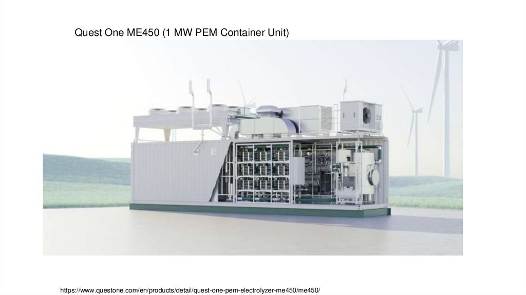
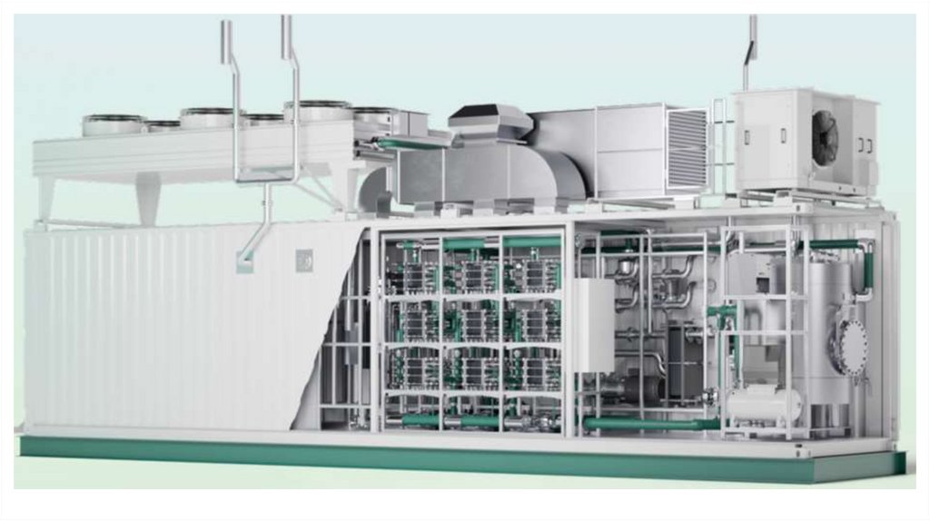
Quest One ME450 (1 MW PEM Container Unit)https://www.questone.com/en/products/detail/quest-one-pem-electrolyzer-me450/me450/
24.
25.
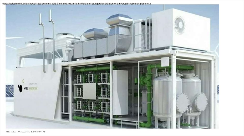
https://fuelcellsworks.com/news/h-tec-systems-sells-pem-electrolyzer-to-university-of-stuttgart-for-creation-of-a-hydrogen-research-platform-226.
3D Model Comments - 3/2727.
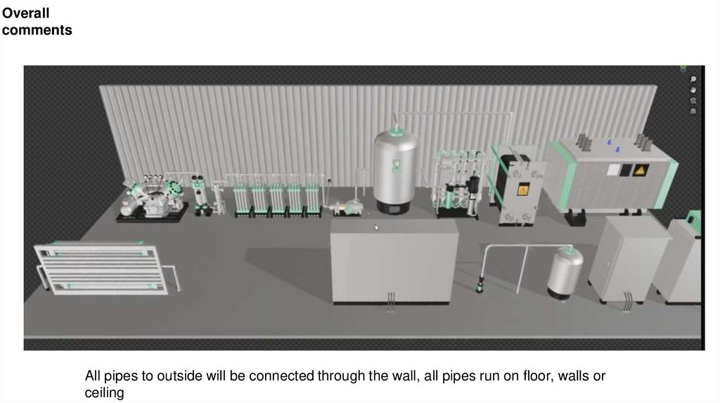
Overallcomments
Remove wall, put in “framing” in as if a
building
Remove lattice so
can see tanks
from all angles
(more of a “rack
style)
Put a display on this
side too (outside
move
viewing access)
Too much empty space, all these components will be crowded
together.
All pipes to outside will be connected through the wall, all pipes run on floor, walls or
ceiling
28.
Overallcomments
All pipes to outside will be connected through the wall, all pipes run on floor, walls or
ceiling
29.
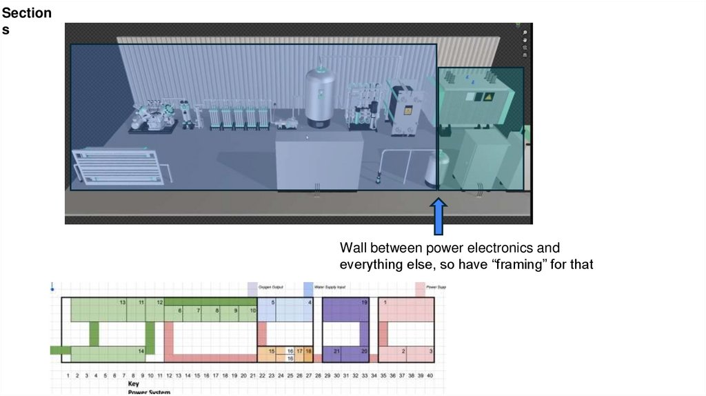
Sections
Wall between power electronics and
everything else, so have “framing” for that
30.
Doorsend door
end doo
2 double wide doors
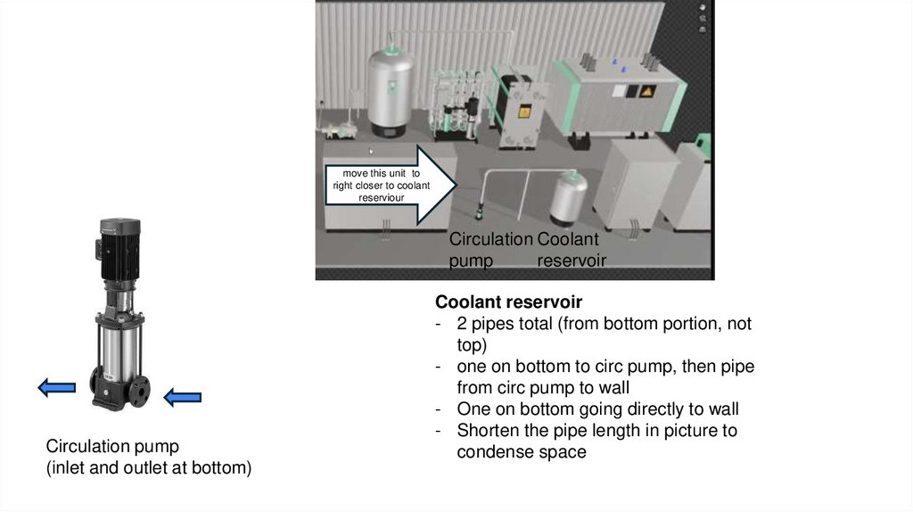
31.
move this unit toright closer to coolant
reserviour
Circulation Coolant
pump
reservoir
Circulation pump
(inlet and outlet at bottom)
Coolant reservoir
- 2 pipes total (from bottom portion, not
top)
- one on bottom to circ pump, then pipe
from circ pump to wall
- One on bottom going directly to wall
- Shorten the pipe length in picture to
condense space
32.
Dryer andSeparator
H2 outlet (upper
port) connected to
dryer unit
H2 inlet
from
manifold
here (lower
port)
Dryer
Gas out
here
Gas in
here
- Pointing the wrong way in model
- Connections are at the flanges
shown
33.
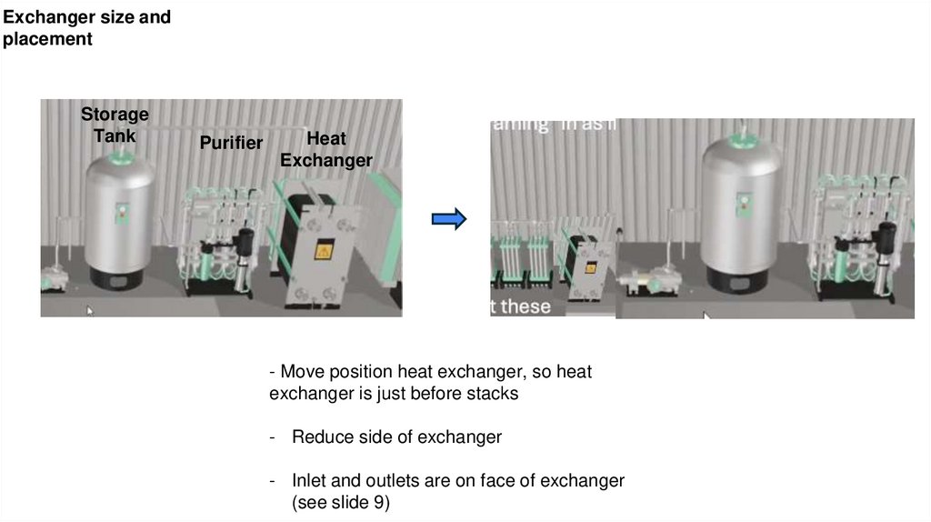
Exchanger size andplacement
Storage
Tank
Purifier
Heat
Exchanger
- Move position heat exchanger, so heat
exchanger is just before stacks
- Reduce side of exchanger
- Inlet and outlets are on face of exchanger
(see slide 9)
34.
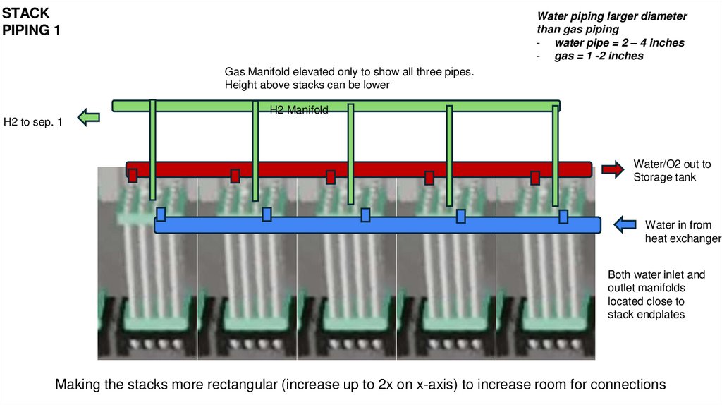
STACKPIPING 1
Water piping larger diameter
than gas piping
- water pipe = 2 – 4 inches
- gas = 1 -2 inches
Gas Manifold elevated only to show all three pipes.
Height above stacks can be lower
H2 Manifold
H2 to sep. 1
Water/O2 out to
Storage tank
Water in from
heat exchanger
Both water inlet and
outlet manifolds
located close to
stack endplates
Making the stacks more rectangular (increase up to 2x on x-axis) to increase room for connections
35.
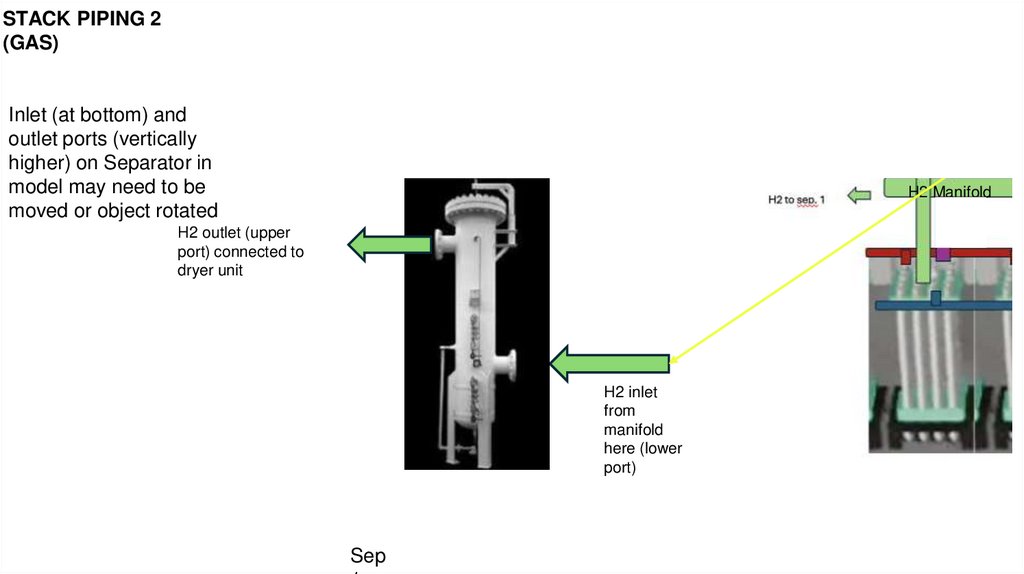
STACK PIPING 2(GAS)
Inlet (at bottom) and
outlet ports (vertically
higher) on Separator in
model may need to be
moved or object rotated
O2 Manifold
H2 Manifold
H2 outlet (upper
port) connected to
dryer unit
H2 inlet
from
manifold
here (lower
port)
Sep
36.
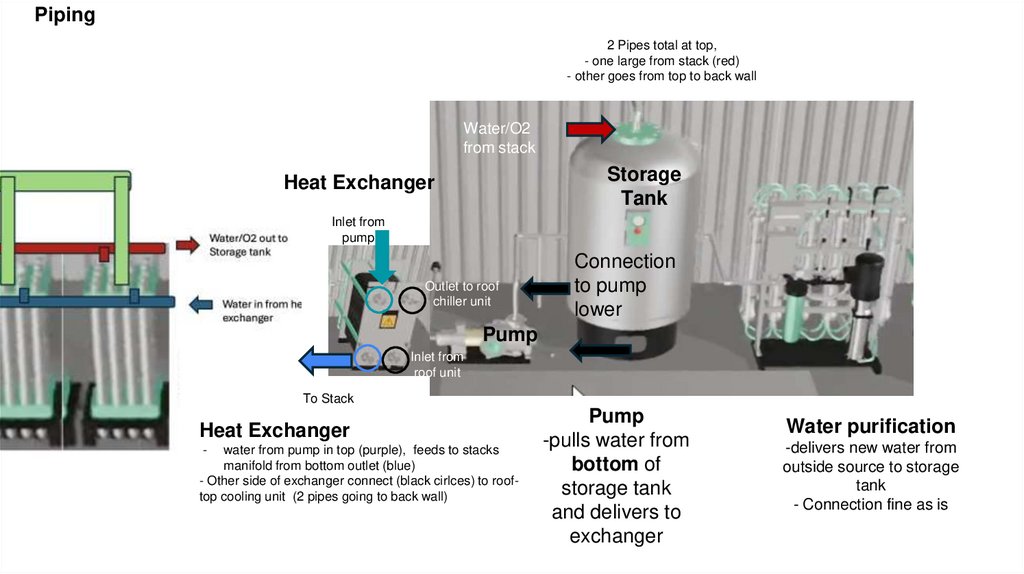
Piping2 Pipes total at top,
- one large from stack (red)
- other goes from top to back wall
Water/O2
from stack
Storage
Tank
Heat Exchanger
Inlet from
pump
Outlet to roof
chiller unit
Connection
to pump
lower
Pump
Inlet from
roof unit
To Stack
Heat Exchanger
-
water from pump in top (purple), feeds to stacks
manifold from bottom outlet (blue)
- Other side of exchanger connect (black cirlces) to rooftop cooling unit (2 pipes going to back wall)
Pump
-pulls water from
bottom of
storage tank
and delivers to
exchanger
Water purification
-delivers new water from
outside source to storage
tank
- Connection fine as is
37.
Flanges and“Wall
Connections”
“wall
connection”
example
Pipe flange
-
All internal piping to outside
walls should end with a flange
at a spot on the wall
38.
Connections tooutside
1)
2)
3)
4)
5)
DI water purifier (1 connection)
Hydrogen storage tanks (1 connection)
Electrolyte storage tank (1 connection)
Coolant reservoir (2 connections)
Heat exchanger (2 connections)
DI water purifier
Electrolyte
Storage Tank
Hydrogen storage
Tanks
Heat Exchanger
Coolant Reservoir
39.
https://www.schaeffler.com/en/media/pressreleases/press-releases-detail.jsp?id=8802924940.
Heat Exchanger41.
Stack Rack - 4/1/202542.
43.
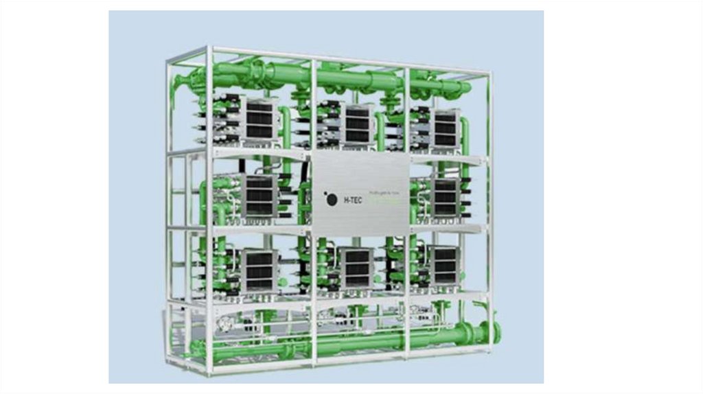
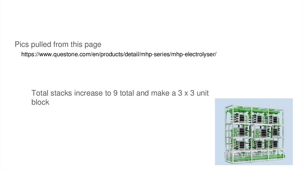
Pics pulled from this pagehttps://www.questone.com/en/products/detail/mhp-series/mhp-electrolyser/
Total stacks increase to 9 total and make a 3 x 3 unit
block
44.
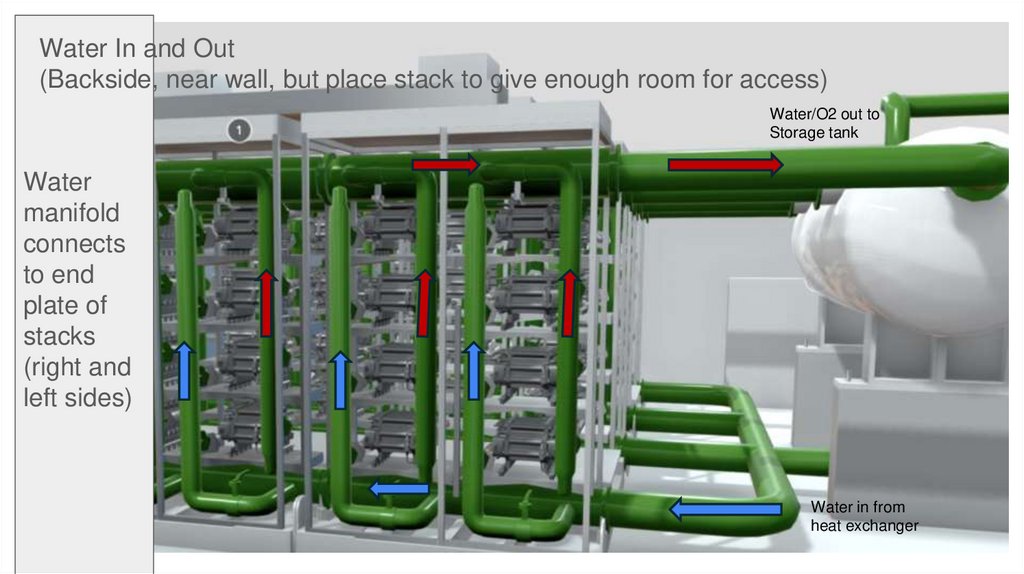
Water In and Out(Backside, near wall, but place stack to give enough room for access)
Water/O2 out to
Storage tank
Water
manifold
connects
to end
plate of
stacks
(right and
left sides)
Water in from
heat exchanger
45.
Hydrogen Manifold (Assume this is the other of the stack in of picture on slide 2)H2 to separator
(H2 manifold
outlet is opposite
from water)
The H2 manifold would
be visible from inside
the unit
46.
47.
False Floor (everything on false floor except large storage tank and pump)48.
Second Tier Comments - 4/10/202549.
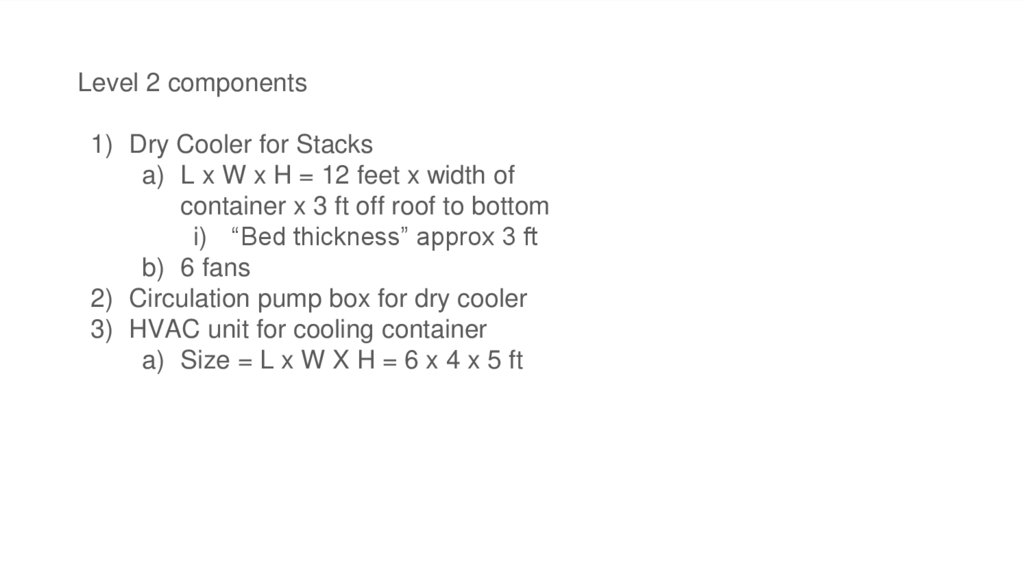
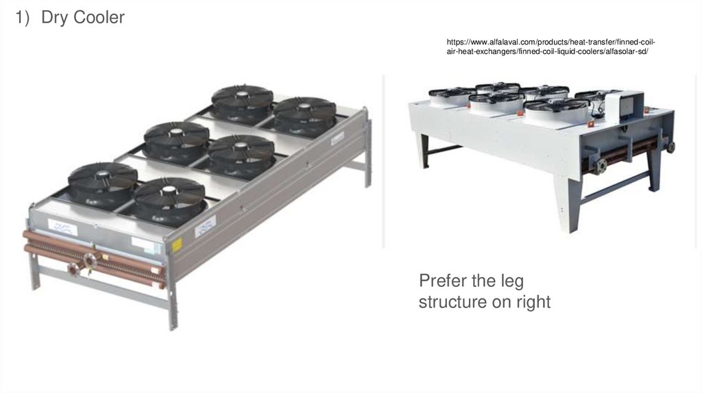
Level 2 components1) Dry Cooler for Stacks
a) L x W x H = 12 feet x width of
container x 3 ft off roof to bottom
i) “Bed thickness” approx 3 ft
b) 6 fans
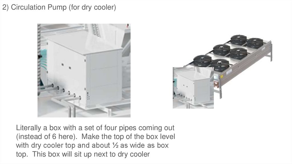
2) Circulation pump box for dry cooler
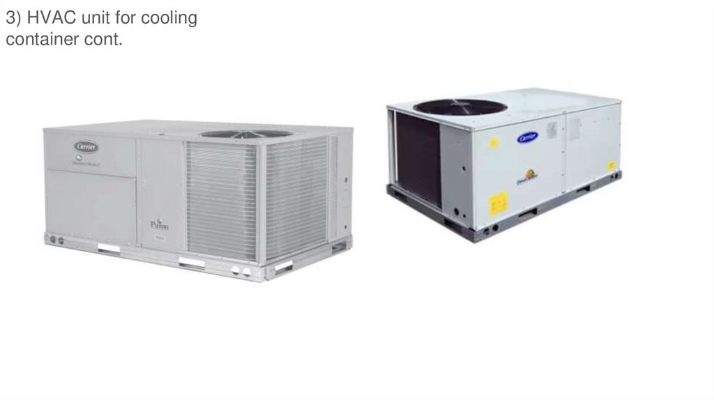
3) HVAC unit for cooling container
a) Size = L x W X H = 6 x 4 x 5 ft
50.
Quest One ME450 (1 MW PEM Container Unit)https://www.questone.com/en/products/detail/quest-one-pem-electrolyzer-me450/me450/
51.
52.
https://fuelcellsworks.com/news/h-tec-systems-sells-pem-electrolyzer-to-university-of-stuttgart-for-creation-of-a-hydrogen-research-platform-253.
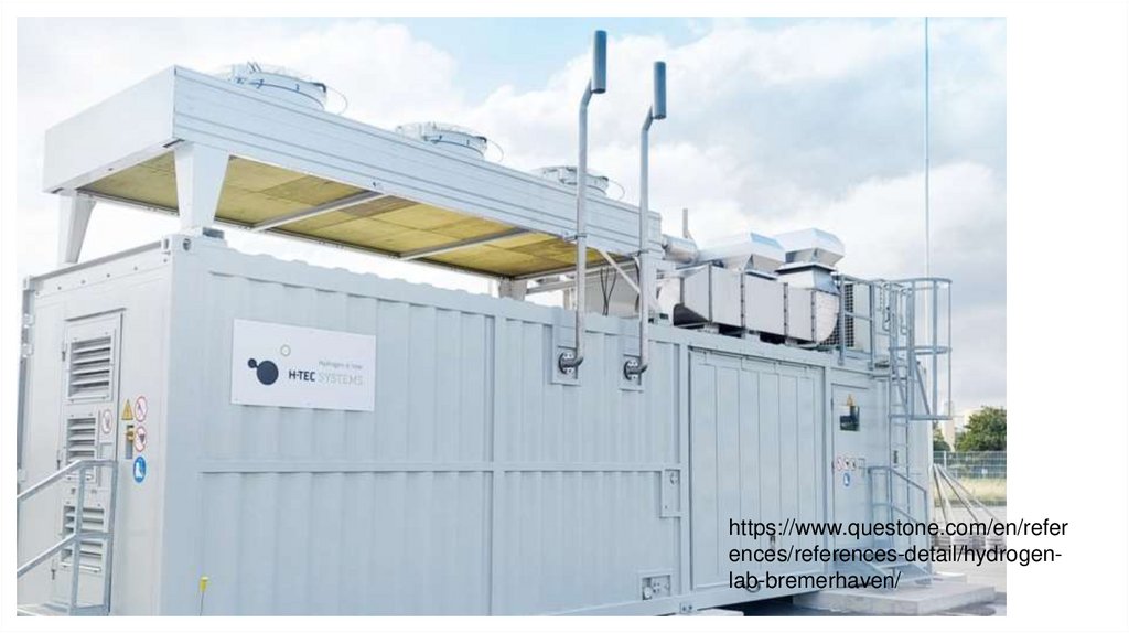
https://www.questone.com/en/references/references-detail/hydrogenlab-bremerhaven/
54.
https://www.questone.com/en/references/references-detail/hydrogenlab-bremerhaven/
55.
1) Dry Coolerhttps://www.alfalaval.com/products/heat-transfer/finned-coilair-heat-exchangers/finned-coil-liquid-coolers/alfasolar-sd/
Prefer the leg
structure on right
56.
2) Circulation Pump (for dry cooler)Literally a box with a set of four pipes coming out
(instead of 6 here). Make the top of the box level
with dry cooler top and about ½ as wide as box
top. This box will sit up next to dry cooler
57.
3) HVAC unit for coolingcontainer cont.
58.
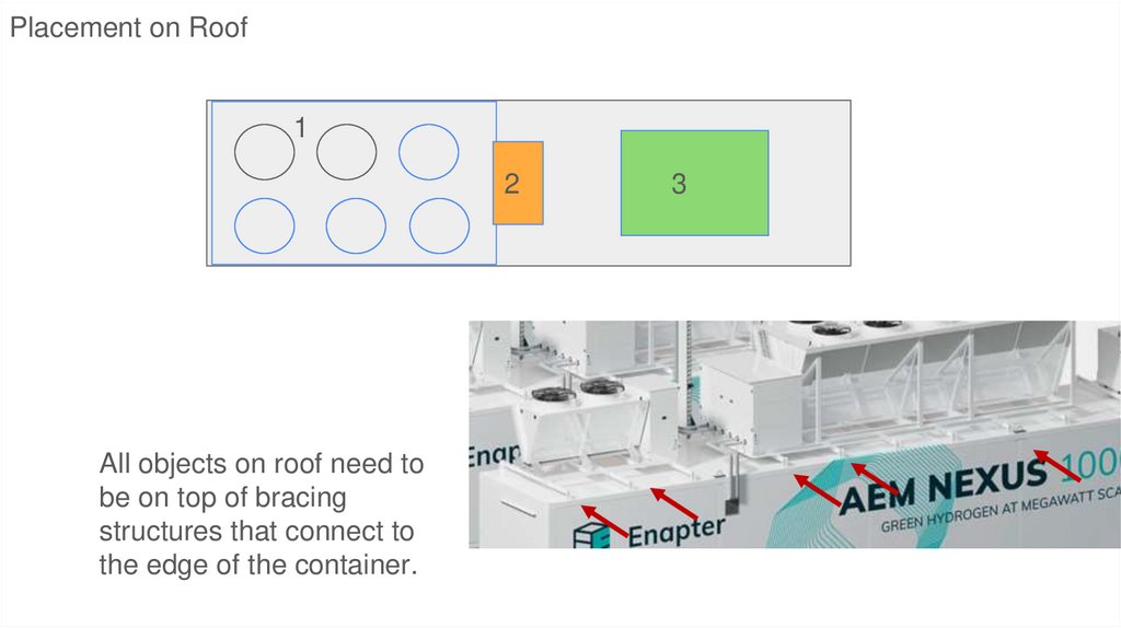
Placement on Roof1
2
All objects on roof need to
be on top of bracing
structures that connect to
the edge of the container.
3
59.
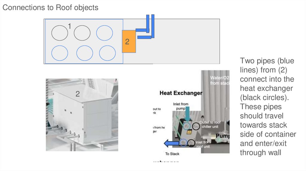
Connections to Roof objects1
2
2
Two pipes (blue
lines) from (2)
connect into the
heat exchanger
(black circles).
These pipes
should travel
towards stack
side of container
and enter/exit
through wall
60.
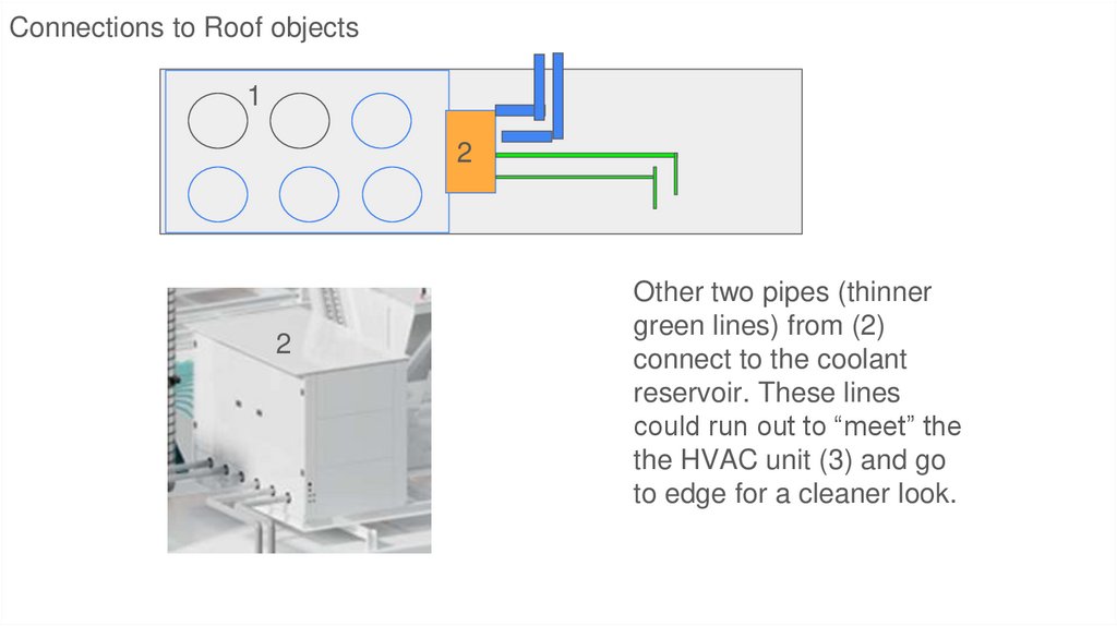
Connections to Roof objects1
2
2
Other two pipes (thinner
green lines) from (2)
connect to the coolant
reservoir. These lines
could run out to “meet” the
the HVAC unit (3) and go
to edge for a cleaner look.