


.")
.")


")


 electronics
Similar presentations:


")

")


Understanding Olympian Generator Set Schematics
1. Understanding Olympian Generator Set Schematics
Understanding Olympian Generator Set SchematicsLEGF1943
2. Reminder:
• Wire numbers are identified on ALLOlympian generator set drawings.
• Terminal numbers ARE NOT identified on
all Olympian generator set drawings.
Understanding Olympian Generator Set Schematics
LEGF1943
3. Topics Covered
• Sample Schematic• Customer Connections (Wires)
• Ribbon Cable Interface
• Component Identification
• Grid References
• Voltage Changes
Understanding Olympian Generator Set Schematics
LEGF1943
4. Sample Schematic
Understanding Olympian Generator Set SchematicsLEGF1943
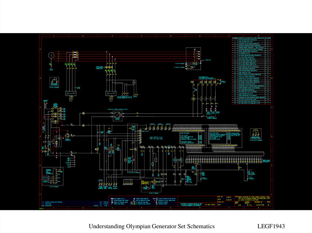
5. Sample Schematic: 4001E Control Panel Details shown may not be applicable to all control panels.
Understanding Olympian Generator Set SchematicsLEGF1943
6. Customer Connections
Understanding Olympian Generator Set SchematicsLEGF1943
7. Customer Connections: Terminals Locations for connection terminals.
CustomerConnection
Terminals
Understanding Olympian Generator Set Schematics
LEGF1943
8. Customer Connections: DC Connections Locations for DC connections.
Customer ConnectionTerminal Strip (DC)
Understanding Olympian Generator Set Schematics
LEGF1943
9. Customer Connections: Wire Numbers Wires on ALL schematics are numbered.
WireNumber
Understanding Olympian Generator Set Schematics
LEGF1943
10. Customer Connections: Terminal Numbers Locations for terminal markings.
CustomerTerminal
Number
Understanding Olympian Generator Set Schematics
LEGF1943
11. Customer Connections: Auto-Start Location for start wires from the ATS.
Auto StartConnection
(from ATS)
Understanding Olympian Generator Set Schematics
LEGF1943
12. Customer Connections: Heater Connections Location for Heaters/Installed Chargers Supply (Shore Power).
AC Connectionfor Heaters and
Installed Battery
Chargers
Understanding Olympian Generator Set Schematics
LEGF1943
13. Customer Connections: Dry Contacts Location for Common Alarm Dry Contact (Optional).
Dry Contact forCommon Alarm
(shown in no
fault condition)
Understanding Olympian Generator Set Schematics
LEGF1943
14. Ribbon Cable Interface
Understanding Olympian Generator Set SchematicsLEGF1943
15. Ribbon Cable Interface Identification
Ribbon Cable InterfaceUnderstanding Olympian Generator Set Schematics
LEGF1943
16. Ribbon Cable Interface Legend of Pin Connections
Legend forRibbon Cable
Interface
Understanding Olympian Generator Set Schematics
LEGF1943
17. Ribbon Cable Interface Example as to how one locates an Annunciator output point.
e.g., Low OilPressure
Annunciator
Connection
(Switches to
Negative on
Fault)
Understanding Olympian Generator Set Schematics
LEGF1943
18. Component Identification
Understanding Olympian Generator Set SchematicsLEGF1943
19. Component Identification Control Board
4001 ControlBoard
Understanding Olympian Generator Set Schematics
LEGF1943
20. Component Identification Expansion Board
4001 ExpansionBoard
Understanding Olympian Generator Set Schematics
LEGF1943
21. Component Identification Alternator
AlternatorUnderstanding Olympian Generator Set Schematics
LEGF1943
22. Component Identification Circuit Breaker
Main LineCircuit Breaker
Circuit Breaker
Enclosure
Understanding Olympian Generator Set Schematics
LEGF1943
23. Component Identification Voltmeter
VoltmeterSelector Switch
Voltmeter
Understanding Olympian Generator Set Schematics
LEGF1943
24. Component Identification Ammeter
AmmeterSelector Switch
Ammeter
Understanding Olympian Generator Set Schematics
LEGF1943
25. Component Identification Engine Interface Module (EIM)
Engine InterfaceModule (EIM)
EIM Fuses
Understanding Olympian Generator Set Schematics
LEGF1943
26. Component Identification Fuel Control Solenoid
Fuel ControlSolenoid
Understanding Olympian Generator Set Schematics
LEGF1943
27. Component Identification Starting Circuit
BatteryStarter
Motor
Battery
Charging
Alternator
Understanding Olympian Generator Set Schematics
LEGF1943
28. Component Identification Senders/Shutdown Switches
High CoolantTemperature
Switch (contact
closes on high
coolant temp.)
Oil Pressure
Sender
Coolant
Temperature
Sender
Low Oil
Pressure
Switch (contact
closes on low
oil pressure)
Understanding Olympian Generator Set Schematics
LEGF1943
29. Component Identification Engine Gauges
EngineTemperature
Gauge
Oil Pressure
Gauge
Understanding Olympian Generator Set Schematics
LEGF1943
30. Component Identification Engine Meters
BatteryVoltmeter
Hours Run
Meter
Understanding Olympian Generator Set Schematics
LEGF1943
31. Component Identification Run Switch
Run/Stop/AutoSwitch
Pole 2
Pole 1
Understanding Olympian Generator Set Schematics
LEGF1943
32. Component Identification Wiring Looms
AC LoomConnection to
Control Panel
(Pin 11)
DC Loom
Connection to
Control Panel
(Pin 7)
Understanding Olympian Generator Set Schematics
LEGF1943
33. Grid References
Understanding Olympian Generator Set SchematicsLEGF1943
34. Grid Reference Identifying the coordinates for the wire destination.
Wires Continueat Grid
Reference D04
Understanding Olympian Generator Set Schematics
LEGF1943
35. Grid References Locating the destination based on the coordinates.
Understanding Olympian Generator Set SchematicsLEGF1943
36. Voltage Changes
Understanding Olympian Generator Set SchematicsLEGF1943
37. Voltage Changes
Link Sets the Voltage Sensing Level toControl Board (If the link is in the
wrong position, the control board may
be permanently damaged)
Understanding Olympian Generator Set Schematics
LEGF1943
38.
Understanding Olympian Generator Set SchematicsLEGF1943