


Similar presentations:


")


Sky L1,L2 service manual
1.
SkyL1,L2
service manual
2.
AgendaProduct ………………………p3
Disassembly guide ……… p4-p14
L1&L2 Repairing guide……p15-p24
2
3.
ProductModel
Platform
LCD
Sup
Memory
MTK6575
4.0WVGA 480*800 16.7M TFT
Dual SIM
Capacitor TP
WCDMA : 2100 MHz GSM 900/1800 MHZ
4GB+4Gb (Nand&sdram+RAM
Battery
2200mAh
Charger:
Travelling
USB cable:
micro 5 pin
Earphone 3.5jack
CAM
Main 5M + SUB 0.3M CMOS
System
Android4.0
Sup
T-Flash、MP3、MP4(REC 、FM、USB、ATV
Sup
GPS、WIFI、BT 、FM
3
4.
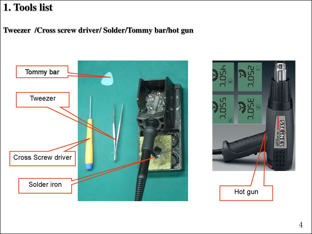
1. Tools listTweezer /Cross screw driver/ Solder/Tommy bar/hot gun
Tommy bar
Tweezer
Cross Screw driver
Solder iron
Hot gun
4
5.
2. Battery cover disassemblyGuide
Disassemble battery cover as below picture;
Battery
cover
5
6.
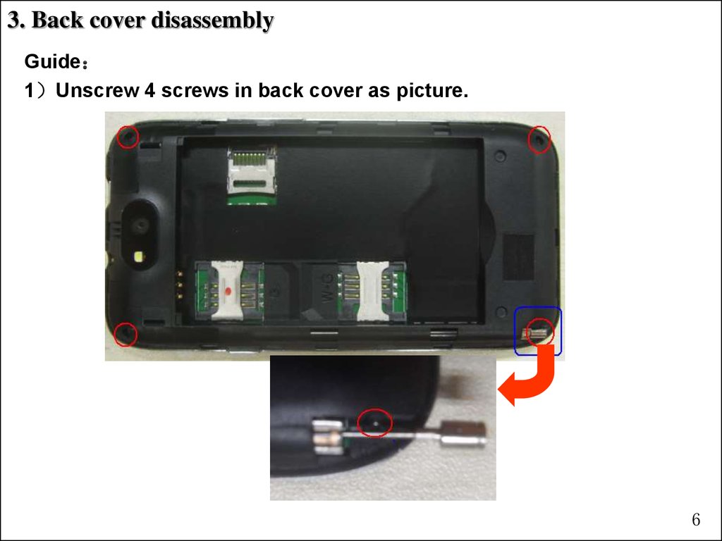
3. Back cover disassemblyGuide
1 Unscrew 4 screws in back cover as picture.
6
7.
3. Back cover disassemblyGuide
2 Disassemble back cover with tool as picture
Back cover
Vibrator
Speaker
7
8.
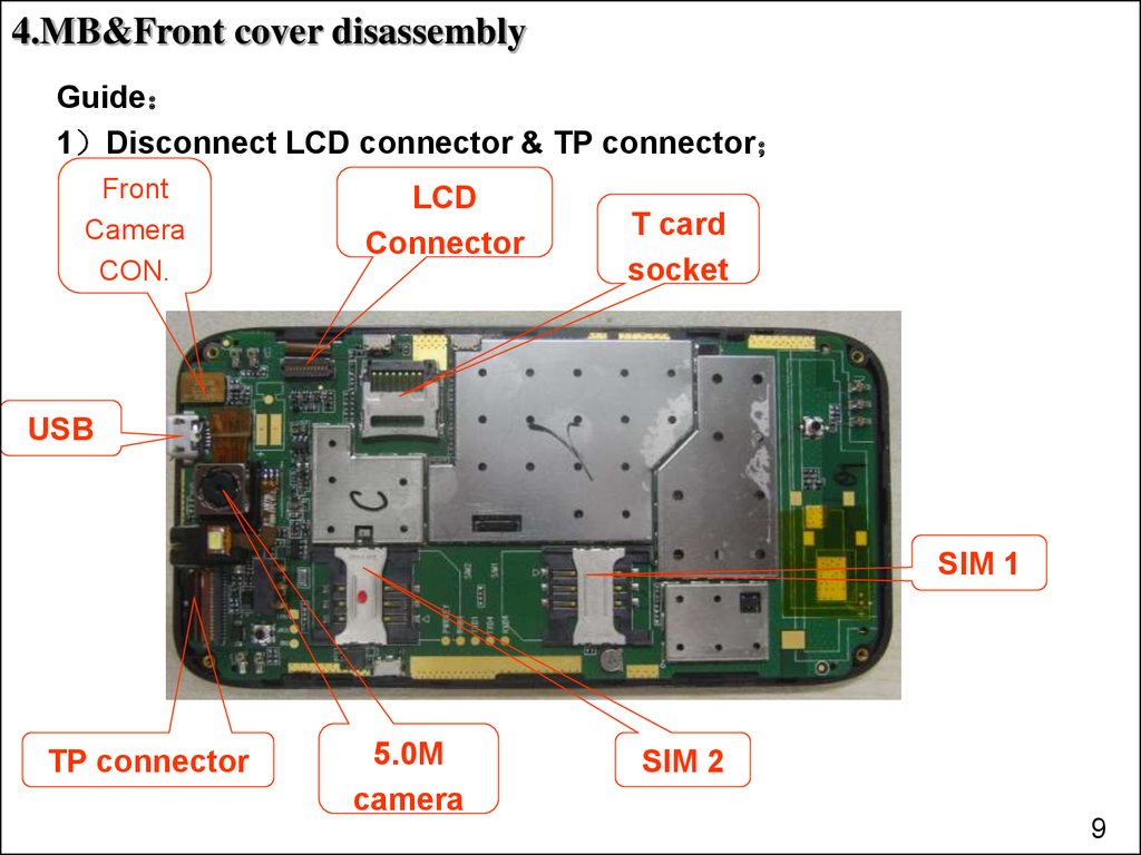
4.MB&Front cover disassemblyGuide
1 Disconnect LCD connector & TP connector
Front
Camera
CON.
LCD
Connector
T card
socket
USB
SIM 1
TP connector
5.0M
camera
SIM 2
9
9.
4.MB&Front cover disassembly2 Disconnect one connector as below picture
9
10.
4.MB&Front cover disassembly3 Disassemble MB, then get it out
Light
sensor
TP
Receiver
Sub CAM
CON.
PCBA
Sub CAM
Main CAM
10
11.
4.MB&Front cover disassembly4 Disconnect LCD connector and Separate LCD from PCBA
LCD
connector
LCD
LCD
connector
11
12.
5.CAM disassemblyUse tweezer to disassemble CAM
12
13.
6. TP disassembly1 Use hot air gun to disassemble
1、Hot air gun degree set as 120℃
2、Use hot air to heat TP for 2~3 minute.
13
14.
6. &TP disassembly2 Separate TP and front cover as below picture.
Note When you replace new TP, please clean the glue tape on
front cover, then stick new glue tape before assemble new TP.
14
15.
L1&L2 RepairingGuide
15
16.
1. LCD display problema. Upgrade SW.
b. Check if LCD or LCD connector broken, if not, replace a new LCD
c. Check LCD connector on MB
d. For L3 repairing, refer schematic diagram
connector
16
17.
2. CAM problema. Check if the CAM connector is loose;
b. Replace with a good CAM, and check if it is due to CAM problem;
c. Check CAM connector
d. Check the components around CAM connector whether there is some
missing ;
Main CAM
connector
Sub CAM
connector
17
18.
3. TP problema. Upgrade SW .
b. Check if TP connector is loose
c. Replace a good TP to verify
d. Check if there is soldering problem on TP connector
TP connector
18
19.
4.Rington problema. Check spring of speaker if it is twisted
b. Check the resister value of speaker
c. Check components around speaker connecting points.
19
20.
5.Receiver problema. Check spring of receiver;
b. Check the resister value of receiver
c. Check the components around receiver connecting points if missing;
20
21.
6.MIC problema. Check MIC if there is poor soldering
b. Replace a new MIC
c. Check if there is some components missing around MIC
MIC
21
22.
7. No vibration or earphone problema. Check spring of vibrator ,check earphone jack if there is poor soldering
b. Check vibrator connecting points on MB
c. Replace new vibrator or earphone jack
c. Check the components around earphone jack and vibrator connecting
points。
Earphone jack
Vibrator connecting
points
22
23.
8. Deada. Check the voltage of battery if in range 3.8V to 4.2V, then check
battery connector
b. Upgrade SW
c. Check power key and the components around it
Power key
23
24.
9.Can not detect SIM card or T carda. Check the socket if there is poor soldering or pin twist
b. Replace new socket
T car socket
SIM1 socket
SIM 2 socket
24
25.
EndQ&A