


 electronics
Similar presentations:


")


")
Positive Pulse Assembly Procedures
1.
Positive Pulse Assembly Procedures1200 System (400-1500 gpm) Shrouded Stator/Mid-Vane Impeller
Positive Pulse Assembly Procedures
1200 System (400-1500 gpm) Shrouded Stator/Mid-Vane Impeller
1.
2.
3.
4.
5.
6.
7.
Apply DC 111 grease to all O-rings before installation, except where noted.
Apply anti-seize lubricant to all threads, except where noted.
Wrap the stator support tube with a rag and support it in the chain vise.
a. Install a 031 O-ring into the groove on the upper bearing sleeve.
b. Install a 033 O-ring against the shoulder of the upper bearing sleeve.
c. Slide the flow diverter onto the upper bearing sleeve. Rotate it to engage the flats.
d. Thread the upper bearing sleeve assembly into the stator support tube (left-hand threads).
e. Use an adjustable spanner wrench on the flow diverter and chain vise grips on the stator support tube to tighten the
upper bearing sleeve assembly to 25 ft-lb.
Wrap a rag around the 2-inch case of the pulser and support in the chain vise.
a. Clean the three stator support tube screw holes in the pulser’s intermediate case.
b. Clean the three stator support tube screws.
c. Spray the holes with Loctite Primer N, wiping off any excess, and then spay the three screws. Allow the primer to dry
for 3-5 minutes.
d. Install a 125 O-ring into the groove on the pulser’s intermediate case.
e. Slide the mid-vane impeller onto the pulser.
f. Slide the stator support tube/upper bearing sleeve assembly onto the pulser and seat it over the 125 O-ring.
Remove pulser from chain vise. Use the split clamp to clamp the OD of the mid-vane impeller in the chain vise.
a. Rotate the stator support tube/upper bearing sleeve assembly to align the stator support tube screw holes with the
holes in the stator support tube.
b. Apply Loctite 242 (temperatures below 150° C) or Loctite 272 (temperatures above 150° C) to the three stator support
screws.
c. Install the flat head screw into the tapered hole on the stator support tube and tighten it to 80 in-lb.
d. Install the two button head cap screws into the other two holes and tighten them to 80 in-lb.
e. Use the grease gun and grease injection ring to fill the cavity between the pulser and stator support tube with DC 111
grease. Use excess grease to cover screw heads.
f. Install a 141 O-ring into the groove on the large diameter end of the stator support tube.
g. Slide the selected shrouded stator onto the stator support tube, engaging its keyway with the key on the stator support
tube and seat it over the O-ring.
h. Install the hub, engaging its keyway with the key on the stator support tube.
i. Install a 032 O-ring into the second of the two grooves (furthest from the end), on the small diameter end of the stator
support tube and a 030 O-ring into the first groove (closest to the end).
j. Thread the nose cap onto the stator support tube (left hand threads). Use two chain vise grips, one on the nose cap and
the other on the hub, to tighten the nose cap to 50 ft-lb.
k. Clean the thread hole in the 1200 system poppet.
l. Apply DC 111 grease to the groove of poppet shaft flange (holds O-ring in place).
m. Install a 020 O-ring into the groove on the poppet shaft flange.
n. Thread the poppet on to the poppet shaft. Use a poppet torque wrench adapter on the poppet and chain vise grips on
hub to tighten the poppet to 16 ft-lb (192 in-lb).
Remove pulser from chain vise. Turn pulser assembly around and use the split clamp to clamp the OD of the mid-vane
impeller in the chain vise.
a. Grease the 2-inch case and the keyway on the bulkhead.
b. Install the key into the keyway onto the pulser.
c. Slide the flow ring/straightener onto the pulser and seat it over the key.
d. Install the snap ring into the groove on the bulkhead.
e. Slide the spacer sleeve, large end first, onto the pulser.
f. Install two 218 O-rings into the grooves on the pulser bulk head.
g. Install the pulser thread cover (do not use anti-seize).
Slightly stretch a 041 O-ring and install it into the groove on the ID of the fishneck.
a. Install the orifice, tapered end last, into the fishneck, verify that the orientation of the orifice is correct.
b. Thread the jam nut, tapered side last, onto the fishneck and install tab lock washer against the jam nut.
c. Install two 042 O-rings into the grooves on the OD of the orifice end of the fishneck
Positive Pulse Assembly
October 2, 2001
Copyright 2000, 2001, Halliburton Energy Services, Inc.
1
2.
Positive Pulse Assembly Procedures1200 System (400-1500 gpm) Shrouded Stator/Mid-Vane Impeller
Thread the orifice retainer onto fishneck. Use a 4" spanner wrench and cheater bar on the orifice retainer and a 5"
spanner wrench as a back-up on the fishneck. to tighten the orifice retainer to 50 ft-lb
e. Install orifice retainer spring lock clip
f. Install a 154 O-ring into the groove in the OD of the orifice retainer.
8. Clamp the flow tube lightly into chain vise near its center, allowing access to the wear sleeve retainer end.
a. Slide pulse generator assembly into the flow tube, engaging the flow ring keyway with the wear sleeve retainer key.
9. Loosen the chain vise and reclamp the flow tube assembly into chain vise on the wear sleeve retainer.
a. Thread the bottom ring into the flow tube. Use a 5" spanner wrench and cheater bar to tighten the bottom ring to 100
ft-lb.
b. Install the spring lock clip onto the bottom ring/wear sleeve retainer.
10. Remove the flow tube from the chain vise. Turn it around and reclamp it in the chain vise near the fishneck end.
a. Thread the fishneck into the flow tube
b. Install the poppet location indicator into the fishneck, engage the dogs in the J-slots and tighten the thumb screws.
c. Adjust the poppet to ±0.004" of correct stand-off distance (use poppet location indicator, calibrated to 0.900")
d. Use a 5" spanner wrench and cheater bar to tighten the jam nut to 100-150 ft-lb, without rotating the fishneck.
e. Recheck the poppet stand-off distance.
f. Remove the poppet location indicator before hammering
g. Use a hammer and punch to bend jam nut lock washer tabs into the grooves on the fishneck and jam nut.
h. Install two 350 O-rings into the grooves on the fishneck and protect with electrical tape.
i. Write the following information on the flow tube:
Pulser Type
Pulser SN
Length of Flow Tube Assembly
Stator Angle
Impeller Angle
Orifice Size
Orifice Stand Off Distance
a) Draw a line from the keyway on bottom ring to the top of the fishneck.
d.
2
Connection
Torque
ft-lb
N-m
Upper Bearing Sleeve to Stator Support Tube
Stator Support Tube Screws (80 in-lb)
Nose Cap
Poppet
Orifice Retainer to Fishneck
Bottom Ring Assembly to Flowtube
Fishneck Jam Nut
25
34
9
50
68
16
22
50
68
100
136
100-150 136-203
Part No.
O-Ring Kits
Kit Contents
413449
O-ring Kit Top Bearing Sleeve Change
220371
O-ring Kit Stator Change (1200)
413451
032653
412429
220368
O-ring Kit Impeller Change
O-ring Kit Poppet Change Solar 175
O-ring Kit Bulkhead and Orienter
O-ring Kit Fishneck/Orifice Change (1200)
1 x 033
1 x 031
1 x 141
1 x 030
1 x 032
1 x 046 for #2 Wear Sleeve ID
1 x 125
1 x 020
6 x 218
1 x 041
2 x 042
1 x 154
3 x 350 (one for 1-inch spacer)
Copyright 2000, 2001, Halliburton Energy Services, Inc.
October 2, 2001
Positive Pulse Assembly
3.
Positive Pulse Assembly Procedures650 System (225-650 gpm) Shrouded Stator/Mid-Vane Impeller
650 System (225-650 gpm) Shrouded Stator/Mid-Vane Impeller
1.
2.
3.
4.
5.
6.
7.
8.
9.
Apply DC 111 grease to all O-rings before installation, except where noted.
Apply anti-seize lubricant to all threads, except where noted.
Wrap the stator support tube with a rag and support it in the chain vise.
a. Install a 031 O-ring into the groove on the upper bearing sleeve.
b. Install a 033 O-ring against the shoulder of the upper bearing sleeve.
c. Slide the flow diverter onto the upper bearing sleeve. Rotate it to engage the flats.
d. Thread the upper bearing sleeve assembly into the stator support tube (left-hand threads).
e. Use an adjustable spanner wrench on the flow diverter and chain vise grips on the stator support tube to tighten the
upper bearing sleeve assembly to 25 ft-lb.
Wrap a rag around the 2-inch case of the pulser and support in the chain vise.
a. Clean the three stator support tube screw holes in the pulser’s intermediate case.
b. Clean the three stator support tube screws.
c. Spray the holes with Loctite Primer N, wiping off any excess, and then spay the three screws. Allow the primer to dry
for 3-5 minutes.
d. Install a 125 O-ring into the groove on the pulser’s intermediate case.
e. Slide the mid-vane impeller onto the pulser.
f. Slide the stator support tube/upper bearing sleeve assembly onto the pulser and seat it over the 125 O-ring.
Remove pulser from chain vise. Use the split clamp to clamp the OD of the mid-vane impeller in the chain vise.
a. Rotate the stator support tube/upper bearing sleeve assembly to align the stator support tube screw holes with the
holes in the stator support tube.
b. Apply Loctite 242 (temperatures below 150° C) or Loctite 272 (temperatures above 150° C) to the three stator support
screws.
c. Install the flat head screw into the tapered hole on the stator support tube and tighten it to 80 in-lb.
d. Install the two button head cap screws into the other two holes and tighten them to 80 in-lb.
e. Use the grease gun and grease injection ring to fill the cavity between the pulser and stator support tube with DC 111
grease. Use excess grease to cover screw heads.
f. Install a 141 O-ring into the groove on the large diameter end of the stator support tube.
g. Slide the selected shrouded stator onto the stator support tube, engaging its keyway with the key on the stator support
tube and seat it over the O-ring.
h. Install the hub, engaging its keyway with the key on the stator support tube.
i. Install a 032 O-ring into the second of the two grooves (furthest from to end), on the small diameter end of the stator
support tube and a 030 O-ring into the first groove (closest to end).
j. Thread the nose cap onto the stator support tube (left hand threads). Use two chain vise grips, one on the nose cap and
the other on the hub, to tighten the nose cap to 50 ft-lb.
Clean the thread hole in the standard poppet (standard orifice).
a. Apply DC 111 grease to the groove of poppet shaft flange (holds O-ring in place).
b. Install a 020 O-ring into the groove on the poppet shaft flange.
c. Thread the poppet on to the poppet shaft. Use a poppet torque wrench adapter on the poppet and chain vise grips on
hub to tighten the poppet to 16 ft-lb (192 in-lb).
Remove pulser from chain vise. Turn pulser assembly around and use the split clamp to clamp the OD of the mid-vane
impeller in the chain vise.
a. Grease the 2-inch case and the keyway on the bulkhead.
b. Install the key into the keyway onto the pulser.
c. Slide the flow ring/straightener onto the pulser and seat it over the key.
d. Install the snap ring into the groove on the bulkhead.
e. Slide the spacer sleeve, large end first, onto the pulser.
f. Install two 218 O-rings into the grooves on the pulser bulk head.
g. Install the pulser thread cover (do not use anti-seize).
Install a 036 O-ring into the groove on the ID of the orifice retainer closest to the internal shoulder.
a. Install the orifice into the bore of the orifice retainer
b. Install a 229 O-ring into the thread relief just above the orifice.
c. Install jam nut, jam nut lock tab washer, and orifice retainer lock tab washer onto the fishneck.
d. Thread the orifice retainer onto fishneck.
Clamp the fishneck in the chain vise. Do not clamp on the O-ring groove area.
a. Use a 3-1/2" spanner wrench and cheater bar to tighten the orifice retainer to 50-100 ft-lb.
Positive Pulse Assembly
October 2, 2001
Copyright 2000, 2001, Halliburton Energy Services, Inc.
3
4.
Positive Pulse Assembly Procedures650 System (225-650 gpm) Shrouded Stator/Mid-Vane Impeller
b.
Using a hammer and punch bend the orifice retainer lock washer tabs into the notches on the orifice retainer and
fishneck.
c. Install a 339 O-ring into the groove on the OD of the orifice retainer
10. Clamp the flow tube in the chain vise allowing access to the fishneck end.
a. Verify that the #2 wear sleeve does NOT have a groove. Do not use a flow tube with a groove in the #2 wear sleeve
with a shrouded stator.
11. Remove the flow tube from the chain vise. Turn it around and reclamp it in the chain vise near its center allowing access to
the wear sleeve retainer end.
a. Slide pulse generator assembly into the flow tube, engaging the flow ring keyway with the wear sleeve retainer key.
b. Thread the bottom ring into the flow tube.
12. Loosen the chain vise and reclamp the flow tube assembly into chain vise on the wear sleeve retainer.
a. Use a 4" spanner wrench and cheater bar to tighten the bottom ring to 100 ft-lb.
b. Install the spring lock clip onto the bottom ring/flow tube joint.
13. Remove the flow tube from the chain vise. Turn it around and reclamp it in the chain vise near the fishneck end.
a. Thread the fishneck into the flow tube and adjust the poppet to the correct spacing using the 650 poppet setting tool.
b. Use a 4" spanner wrench and cheater bar to tighten the jam nut to 100-150 ft-lb.
c. Mark a set of aligned notches on the jam nut and flow tube for the tab lock washer. Tighten the jam nut slightly if
required.
d. Loosen the jam nut without rotating the fishneck.
e. Align the tab lock washer with the marked notch on the flowtube and hand tighten the jam nut.
f. Use a punch and hammer to bend the correct tab of the lock washer into the marked notch on the flow tube.
g. Retighten the jam nut until the marked notches are aligned.
h. Recheck the poppet setting.
i. Use a hammer and punch to bend the other tab of the lock washer tab into the marked notch on the jam nut.
j. Install two 345 O-rings into the grooves on the fishneck and protect them electrical tape.
k. Write the following information on the flow tube:
Pulser Type
Pulser SN
Length of Flow Tube Assembly
Stator Angle
Impeller Angle
Orifice Size
a) Draw a line from the keyway on bottom ring to the top of the fishneck.
4
Connection
Torque
ft-lb
N-m
Upper Bearing Sleeve to Stator Support Tube
Stator Support Tube Screws (80 in-lb)
Nose Cap
Poppet
Orifice Retainer to Fishneck
Bottom Ring Assembly to Flowtube
Fishneck Jam Nut
25
34
9
50
68
16
22
50-100 68-136
100
136
100-150 136-203
Part No.
O-Ring Kits
Kit Contents
413449
O-ring Kit Top Bearing Sleeve Change
413450
O-ring Kit Stator Change
413451
032653
412429
412424
O-ring Kit Impeller Change
O-ring Kit Poppet Change Solar 175
O-ring Kit Bulkhead and Orienter
O-ring Kit Fishneck/Orifice Change (650)
1 x 033
1 x 031
1 x 141
1 x 030
1 x 032
1 x 044 for # 2 Wear Sleeve ID
1 x 125
1 x 020
6 x 218
1 x 036
1 x 229
1 x 339
3 x 345 (one for 1-inch spacer)
Copyright 2000, 2001, Halliburton Energy Services, Inc.
October 2, 2001
Positive Pulse Assembly
5.
Positive Pulse Assembly Procedures650 System (225-650 gpm)
650 System (225-650 gpm)
1.
2.
3.
4.
5.
6.
7.
8.
Apply DC 111 grease to all O-rings before installation, except where noted.
Apply anti-seize lubricant to all threads, except where noted.
Wrap the stator support tube with a rag and support it in the chain vise.
a. Install a 031 O-ring into the groove on the upper bearing sleeve.
b. Install a 033 O-ring against the shoulder of the upper bearing sleeve.
c. Slide the wear ring onto the stator support tube.
d. Thread the upper bearing sleeve assembly into the stator support tube (left-hand threads).
e. Use a 1-1/4" to 3 " adjustable spanner wrench on the upper bearing sleeve and chain vise grips on the stator support
tube to tighten the upper bearing sleeve assembly to 25 ft-lb.
Wrap a rag around the 2-inch case of the pulser and support in the chain vise.
a. Clean the three stator support tube screw holes in the pulser’s intermediate case.
b. Install a 125 O-ring into the groove on the pulser’s intermediate case.
c. Slide the impeller onto the pulser vane end last.
d. Slide the stator support tube/upper bearing sleeve assembly onto the pulser and seat it over the 125 O-ring.
Remove pulser from chain vise. Use the split clamp to clamp the OD of the impeller body in the chain vise.
a. Rotate the stator support tube/upper bearing sleeve assembly to align the stator support tube screw holes with the
holes in the stator support tube.
b. Apply Primer N and Loctite 242 (temperatures below 150° C) or Loctite 272 (temperatures above 150° C) to the three
stator support screws.
c. Install the flat head screw into the tapered hole on the stator support tube and tighten it to 80 in-lb.
d. Install the two button head cap screws into the other two holes and tighten them to 80 in-lb.
e. Use the grease gun adapter to fill the cavity between the pulser and stator support tube with DC 111 grease. Use
excess grease to cover screw heads.
f. Install a 141 O-ring into the groove on the large diameter end of the stator support tube.
g. Slide the selected stator onto the stator support tube, engaging its keyway with the key on the stator support tube and
seat it over the O-ring.
h. Install the shroud, engaging its keyway with the key on the stator support tube.
a) Install a 032 O-ring into the second of the two grooves (furthest from the end), on the small diameter end of the stator
support tube and a 030 O-ring into the first groove (closest to the end).
i. Thread the nose cap onto the stator support tube (left hand threads). Use two chain vise grips, one on the nose cap and
the other on the stator vanes, to tighten the nose cap to 50 ft-lb.
j. Clean the thread hole in the standard poppet (standard orifice).
k. Apply DC 111 grease to the groove of poppet shaft flange (holds O-ring in place).
l. Install a 020 O-ring into the groove on the poppet shaft flange.
m. Thread the poppet on to the poppet shaft. Use a poppet torque wrench adapter on the poppet and chain vise grips on
the stator vanes to tighten the poppet to 16 ft-lb (192 in-lb).
Remove pulser from chain vise. Turn pulser assembly around and use the split clamp to clamp the OD of the impeller
body in the chain vise.
a. Grease the 2-inch case and the keyway on the bulkhead.
b. Install the key into the keyway onto the pulser.
c. Slide the flow ring/straightener onto the pulser and seat it over the key.
d. Install the snap ring into the groove on the bulkhead.
e. Slide the spacer sleeve, large end first, onto the pulser.
f. Install two 218 O-rings into the grooves on the pulser bulk head.
g. Install the pulser thread cover (do not use anti-seize).
Install a 036 O-ring into the groove on the ID of the orifice retainer closest to the internal shoulder.
a. Install the orifice into the bore of the orifice retainer
b. Install a 229 O-ring into the thread relief just above the orifice.
c. Install jam nut, jam nut lock tab washer, and orifice retainer lock tab washer onto the fishneck.
d. Thread the orifice retainer onto fishneck.
Clamp the fishneck in the chain vise. Do not clamp on the O-ring groove area.
a. Use a 3-1/2" spanner wrench and cheater bar to tighten the orifice retainer to 50-100 ft-lb.
b. Using a hammer and punch bend the orifice retainer lock washer tabs into the notches on the orifice retainer and
fishneck.
c. Install a 339 O-ring into the groove on the OD of the orifice retainer
Positive Pulse Assembly
October 2, 2001
Copyright 2000, 2001, Halliburton Energy Services, Inc.
5
6.
Positive Pulse Assembly Procedures650 System (225-650 gpm)
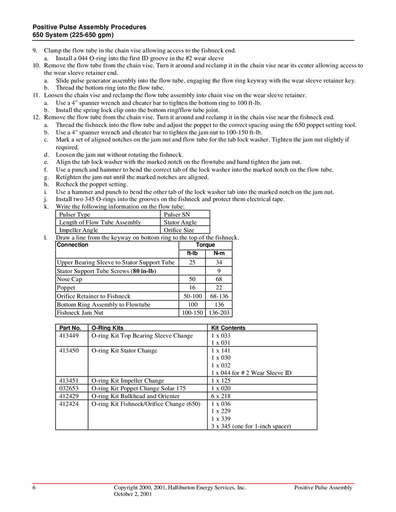
9.
Clamp the flow tube in the chain vise allowing access to the fishneck end.
a. Install a 044 O-ring into the first ID groove in the #2 wear sleeve
10. Remove the flow tube from the chain vise. Turn it around and reclamp it in the chain vise near its center allowing access to
the wear sleeve retainer end.
a. Slide pulse generator assembly into the flow tube, engaging the flow ring keyway with the wear sleeve retainer key.
b. Thread the bottom ring into the flow tube.
11. Loosen the chain vise and reclamp the flow tube assembly into chain vise on the wear sleeve retainer.
a. Use a 4" spanner wrench and cheater bar to tighten the bottom ring to 100 ft-lb.
b. Install the spring lock clip onto the bottom ring/flow tube joint.
12. Remove the flow tube from the chain vise. Turn it around and reclamp it in the chain vise near the fishneck end.
a. Thread the fishneck into the flow tube and adjust the poppet to the correct spacing using the 650 poppet setting tool.
b. Use a 4" spanner wrench and cheater bar to tighten the jam nut to 100-150 ft-lb.
c. Mark a set of aligned notches on the jam nut and flow tube for the tab lock washer. Tighten the jam nut slightly if
required.
d. Loosen the jam nut without rotating the fishneck.
e. Align the tab lock washer with the marked notch on the flowtube and hand tighten the jam nut.
f. Use a punch and hammer to bend the correct tab of the lock washer into the marked notch on the flow tube.
g. Retighten the jam nut until the marked notches are aligned.
h. Recheck the poppet setting.
i. Use a hammer and punch to bend the other tab of the lock washer tab into the marked notch on the jam nut.
j. Install two 345 O-rings into the grooves on the fishneck and protect them electrical tape.
k. Write the following information on the flow tube:
Pulser Type
Pulser SN
Length of Flow Tube Assembly
Stator Angle
Impeller Angle
Orifice Size
l. Draw a line from the keyway on bottom ring to the top of the fishneck.
6
Connection
Torque
ft-lb
N-m
Upper Bearing Sleeve to Stator Support Tube
Stator Support Tube Screws (80 in-lb)
Nose Cap
Poppet
Orifice Retainer to Fishneck
Bottom Ring Assembly to Flowtube
Fishneck Jam Nut
25
34
9
50
68
16
22
50-100 68-136
100
136
100-150 136-203
Part No.
O-Ring Kits
Kit Contents
413449
O-ring Kit Top Bearing Sleeve Change
413450
O-ring Kit Stator Change
413451
032653
412429
412424
O-ring Kit Impeller Change
O-ring Kit Poppet Change Solar 175
O-ring Kit Bulkhead and Orienter
O-ring Kit Fishneck/Orifice Change (650)
1 x 033
1 x 031
1 x 141
1 x 030
1 x 032
1 x 044 for # 2 Wear Sleeve ID
1 x 125
1 x 020
6 x 218
1 x 036
1 x 229
1 x 339
3 x 345 (one for 1-inch spacer)
Copyright 2000, 2001, Halliburton Energy Services, Inc.
October 2, 2001
Positive Pulse Assembly
7.
Positive Pulse Assembly ProceduresSlimhole (350 System 150-350 gpm) IFA Flow Gear
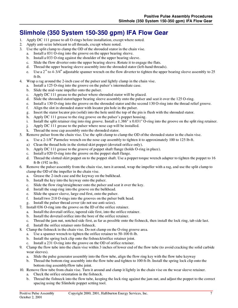
Slimhole (350 System 150-350 gpm) IFA Flow Gear
1.
2.
3.
Apply DC 111 grease to all O-rings before installation, except where noted.
Apply anti-seize lubricant to all threads, except where noted.
Use the split clamp to clamp the OD of the shrouded stator in the chain vise.
a. Install a 031 O-ring into the groove on the upper bearing sleeve.
b. Install a 033 O-ring against the shoulder of the upper bearing sleeve.
c. Slide the flow diverter onto the upper bearing sleeve. Rotate it to engage the flats.
d. Thread the upper bearing sleeve assembly into the shrouded stator (left-hand threads).
e. Use a 2 " to 4-3/4" adjustable spanner wrench on the flow diverter to tighten the upper bearing sleeve assembly to 25
ft-lb.
4. Wrap a rag around the 2-inch case of the pulser and lightly clamp in the chain vise.
a. Install a 125 O-ring into the groove on the pulser’s intermediate case.
b. Slide the mid-vane impeller onto the pulser.
c. Apply DC 111 grease to the pulser where shrouded stator will be placed.
d. Slide the shrouded stator/upper bearing sleeve assembly onto the pulser and seat it over the 125 O-ring.
e. Install a 130 O-ring into the groove on the shrouded stator and the second 130 O-ring into the thread relief groove.
f. Align the slot in shrouded stator with locator pin hole in the pulser.
g. Insert the stator locator pin (solid) into the hole until the top of the pin is flush with the shrouded stator.
h. Apply DC 111 grease to the ring groove on the pulser’s poppet housing.
i. Install the split retainer ring into ring groove. Install a 1.386" x 0.031" O-ring into the groove on the split ring retainer.
j. Apply DC 111 grease to the pulser where nose cap will be installed.
k. Thread the nose cap assembly onto the shrouded stator.
5. Remove pulser from the chain vise. Use the split clamp to clamp the OD of the shrouded stator in the chain vise.
a. Use a 2-1/8" Parmelee wrench on the nose cap assembly to tighten it to approximately 100 to 125 lb-ft.
a) Clean the thread hole in the slotted skirt poppet (dovetail orifice only).
b. Apply DC 111 grease to the groove of poppet shaft flange (holds O-ring in place).
c. Install a 020 O-ring into the groove on the poppet shaft flange.
d. Thread the slotted skirt poppet on to the poppet shaft. Use a poppet torque wrench adapter to tighten the poppet to 16
ft-lb (192 in-lb).
6. Remove the pulser assembly from the chain vise, turn it around, wrap the impeller with a rag, and use the split clamp to
clamp the OD of the impeller in the chain vise.
a. Grease the 2-inch case and the keyway on the bulkhead.
b. Install the key into the keyway onto the pulser.
c. Slide the flow ring/straightener onto the pulser and seat it over the key.
d. Install the snap ring into the groove on the bulkhead.
e. Slide the spacer sleeve, large end first, onto the pulser.
f. Install two 218 O-rings into the grooves on the pulser bulk head.
g. Install the pulser thread cover (do not use anti-seize).
7. Install 036 O-ring into the groove on the ID of the orifice retainer.
a. Install the dovetail orifice, tapered side first, into the orifice retainer.
b. Install the dovetail orifice into the bore of the orifice retainer.
c. Thread the jam nut, notched side first, as far as possible onto the fishneck, then install the lock ring, tab side last.
d. Install the orifice retainer onto fishneck.
8. Clamp the fishneck in the chain vise. Do not clamp on the O-ring groove area.
a. Use a spanner wrench to tighten the orifice retainer to 50-100 ft-lb.
b. Install the spring lock clip onto the fishneck/orifice retainer joint.
c. Install a 231 O-ring into the groove on the OD of orifice retainer.
9. Clamp the flow tube into the chain vise within 3 inches of lower end of the flow tube (to avoid cracking the solid carbide
wear sleeves).
a. Slide the pulse generator assembly into the flow tube, align the flow ring key with the flow tube keyway
b. Thread the bottom ring assembly into the flow tube and tighten to 100 ft-lb. Install the spring lock clip onto the
bottom ring assembly/flow tube joint.
10. Remove flow tube from chain vise. Turn it around and clamp it lightly in the chain vise on the wear sleeve retainer.
a. Check the orifice orientation in the fishneck.
b. Thread the fishneck into the flow tube, keeping the lock ring against the jam nut, and adjust the poppet to the correct
spacing using the Slimhole poppet setting tool.
Positive Pulse Assembly
October 2, 2001
Copyright 2000, 2001, Halliburton Energy Services, Inc.
7
8.
Positive Pulse Assembly ProceduresSlimhole (350 System 150-350 gpm) IFA Flow Gear
c.
d.
e.
f.
g.
h.
i.
Rotate the fishneck so that the locking tab of the lock ring engages with the nearest groove on the flow tube.
Thread the jam nut down until it touches the lock ring. Tighten the chain vise and use a spanner wrench and cheater
bar to tighten the jam nut to 250 ft-lb.
Recheck the poppet spacing.
Install the spring lock clip onto the jam nut/wear sleeve retainer joint.
Install two 235 O-rings into the grooves on the OD of the fishneck and protect with electrical tape.
Write the following information on the flow tube:
Pulser Type
Pulser SN
Length of Flow Tube Assembly
Stator Angle
Impeller Angle
Orifice Size
Draw line from keyway on bottom ring to the top of the fishneck.
Connection
Torque
ft-lb
N-m
Upper Bearing Sleeve to Shrouded Stator
Nose Cap
Poppet
Orifice Retainer to Fishneck
Bottom Ring Assembly to Flowtube
Fishneck Jam Nut
8
25
34
100-125 136-169
16
22
50-100 68-136
100
136
250
339
Part No.
O-Ring Kits
Kit Contents
413449
O-ring Kit Top Bearing Sleeve Change
018739
413451
047930
032653
412429
039396
O-ring Kit Shroud/Stator
O-ring Kit Impeller Change
O-ring 1.386" x 0.031" 70 Duro Nit
O-ring Kit Poppet Change Solar 175
O-ring Kit Bulkhead and Orienter
O-ring Kit Fishneck/Orifice Change (Slimhole)
1 x 033
1 x 031
2 x 130
1 x 125
1 x 020
6 x 218
1 x 036
1 x 231
3 x 235
Copyright 2000, 2001, Halliburton Energy Services, Inc.
October 2, 2001
Positive Pulse Assembly
9.
Positive Pulse Assembly ProceduresSuperslim (200 System 90-200 gpm)
Superslim (200 System 90-200 gpm)
1.
2.
3.
4.
5.
6.
7.
8.
Apply DC 111 grease to all O-rings before installation, except where noted.
Apply anti-seize lubricant to all threads, except where noted.
Use the split clamp to clamp the OD of the shrouded stator in the chain vise.
a. Install a 032 O-ring into the groove on the upper bearing sleeve.
b. Thread the upper bearing sleeve assembly into the shrouded stator (left-hand threads).
c. Use a chain vise grip around the flats on the bearing surface to tighten the upper bearing sleeve assembly to 25 ft-lb.
Wrap a rag around the 2-inch case of the pulser and lightly clamp in the chain vise.
a. Install a 125 O-ring into the groove on the pulser’s intermediate case.
b. Slide the impeller (unshrouded) onto the pulser, vane-end last.
c. Apply DC 111 grease to the pulser where shrouded stator will be placed.
d. Install two 130 O-rings on the shrouded stator, one into the groove and the second into the thread relief groove.
e. Slide the shrouded stator/upper bearing sleeve assembly onto the pulser and seat it over the 125 O-ring.
f. Align the slot in shrouded stator with locator pin hole in the pulser.
g. Insert the stator locator pin (solid) into the hole until the top of the pin is flush with the shrouded stator.
h. Apply DC 111 grease to the ring groove on the pulser’s poppet housing.
i. Install the split retainer ring into ring groove. Install a 1.386" x 0.031" O-ring into the groove on the split retainer ring.
Remove pulser from the chain vise. Use the split clamp to clamp the OD of the shrouded stator in the chain vise.
a. Apply DC 111 grease to the pulser where shroud/nose cap will be placed.
b. Thread the shroud/nose cap assembly onto the shrouded stator.
c. Use a 2-3/4" Parmelee wrench on the shroud/nose cap assembly to tighten it to approximately 100 to 125 lb-ft.
d. Clean the thread hole in the slotted skirt poppet (dovetail orifice only).
e. Apply grease to the groove of poppet shaft flange (holds O-ring in place).
f. Install a 020 O-ring into the groove on the poppet shaft flange.
g. Thread the slotted skirt poppet on to the poppet shaft. Use a poppet torque wrench adapter to tighten the poppet to 16
ft-lb (192 in-lb).
Remove the pulser assembly from the chain vise, turn it around and reclamp it in the chain vise around the body of the
impeller (unshrouded).
a. Grease the 2-inch case and the keyway on the bulkhead.
b. Install the key into the keyway onto the pulser.
c. Slide the flow ring/straightener onto the pulser, tang end last and seat it over the key.
d. Slide the spacer sleeve, large end first, onto the pulser.
e. Install two 218 O-rings into the grooves on the pulser bulkhead.
f. Install the pulser thread cover (do not use anti-seize).
g. Install a 036 O-ring into the groove on the OD of the flow ring/straightener and protect with electrical tape.
Install a 143 O-ring into the groove on the OD of the fishneck.
a. Stretch a 037 O-ring and install it into the groove in the ID of the orifice retainer.
b. Apply DC 111 grease to the internal shoulder of the orifice retainer (to hold the orifice in place).
c. Install the dovetail orifice, tapered side first, into the orifice holder.
d. Install the dovetail orifice/orifice holder, tapered side first, into the orifice retainer.
e. Thread the fishneck into the orifice retainer.
Use the split clamp to clamp the OD of the orifice retainer in the chain vise.
a. Using chain vise grips on fishneck to tighten it to 25 ft-lb. Check that the orifice’s taper is facing towards the orifice
retainer end.
b. Install a wave spring, wave spring spacer, and wave spring onto the top of the fishneck assembly.
c. Write the following information on the pulser:
Pulser type
Pulser SN
Stator angle
Impeller angle
Orifice size
Positive Pulse Assembly
October 2, 2001
Copyright 2000, 2001, Halliburton Energy Services, Inc.
9
10.
Positive Pulse Assembly ProceduresSuperslim (200 System 90-200 gpm)
Connection
Torque
ft-lb
N-m
Upper Bearing Sleeve to Shrouded Stator
Nose Cap
Poppet
Fishneck to Orifice Retainer
10
25
34
100-125 136-169
16
22
25
34
Part No.
O-Ring Kits
Kit Contents
018741
018739
413451
047930
032653
412429
018762
034279
O-ring Kit Stator Extension
O-ring Kit Shrouded Stator
O-ring Kit Impeller Change
O-ring 1.386" x 0.031” 70 Duro Nit
O-ring Kit Poppet Change Solar 175
O-ring Kit Bulkhead and Orienter
O-ring Kit Flow Ring Straightener
O-ring Kit Fishneck/Orifice Superslim
1 x 032
2 x 130
1 x 125
1 x 020
6 x 218
1 x 036
1 x 037
1 x 143
Copyright 2000, 2001, Halliburton Energy Services, Inc.
October 2, 2001
Positive Pulse Assembly