


 Construction
Similar presentations:


")
Catalog. 4-Bolt Connector & Duct Work Accessories
1.
®®
PAGE 1
2.
Table of ContentsPage #
Access Doors
17-19
Air Hammers
23
Air Tools
22
Angle Iron
27
Assembly Instructions
32
Cleats*
8
Conduit
26
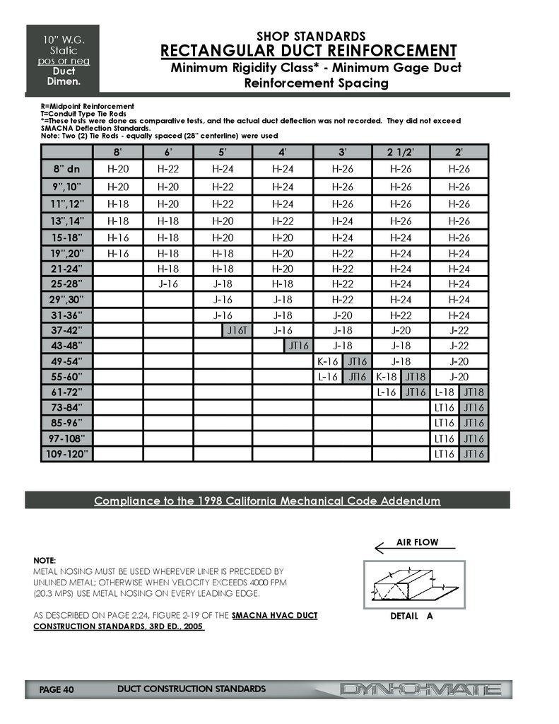
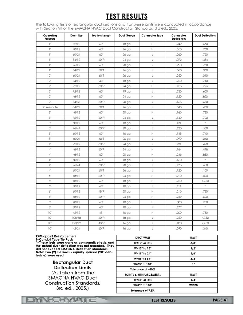
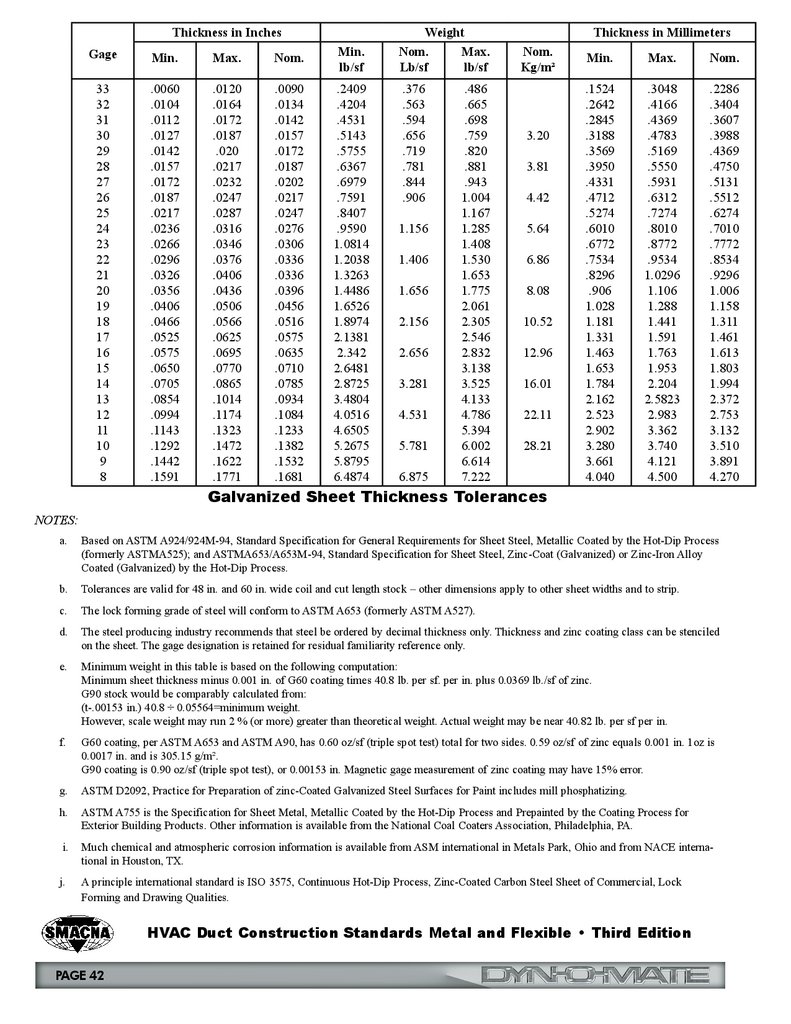
Duct Construction Standards
34-40
Dyn-O-Wrap
21
Dyn-O-Loc & D-Stud, Insertion Tool Machine
26-27
Dyn-O-Claw
27
Dyn-O-Ring
9
Dyn-O-Strut
11
EZ Connector System
4-5
Flat Drive* & Cut-To-Length
14
Flat S* & Cut-To-Length
15
Gasketing
25
Grease Duct Doors
19
Hanging Strap
10-11
H System
2
J System
3
Nail Plates & Hangers
28-31
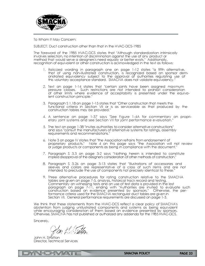
SMACNA Policy
33
Standing S* & Cut-To-Length
16
Test Results
41
TDC Corners
6
TDF Corners
7
Threaded Rod & Accessories
12-13
Tools
23-24
Vane and Rail*
20
Wire Mesh
16
All dimensions shown throughout this
Product Catalog are approximate.
*Manufactured with yellow label.
Color Code Gauge Guide
▪ 14 gauge: Pink
▪ 16 gauge/Aluminum: Yellow
▪ 18 gauge: Purple
▪ 20 gauge: Blue
▪ 22 gauge: White
▪ 24 gauge: Green
▪ 26 gauge: Red
▪ 28 gauge: Orange
▪ 30 gauge: Gray
▪ Stainless: Orange
▪ J Flange: Blue
▪ H Flange: White
PROPRIETARY AND CONFIDENTIAL: The
drawings and specifications contained in
this publication are the exclusive property
of Duro Dyne Corporation and shall not
be divulged, reproduced, copied or used
as the basis for the manufacture or sale
of apparatus without the express written
authorization of Duro Dyne Corporation.
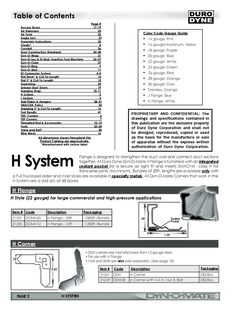
H System
Flange is designed to strengthen the duct wall and connect duct sections
together. All Duro Dyne Dyn-O-Mate H Flange is furnished with an integrated
sealant pocket for a secure air tight fit and meets SMACNA class H for
transverse joints (Aluminum). Bundles of 20ft. lengths are available only with
a Full Truckload order and most styles are available in specialty metals. All Dyn-O-Mate Corners that work in the
H System are a skid qty of 48 boxes.
H Flange
H Style (22 gauge) for large commercial and high-pressure applications
Item # Code
Description
Packaging
21231 DOMH20
H Flange - 20ft
1000ft./Bundle
21235 DOMH12
H Flange - 12ft
1200ft./Bundle
.96’’
Sealant
1.34’’
H Corner
▪ DDH corners are manufactured from 12-gauge steel.
▪ For use with H Flange.
▪ Nuts and Bolts are also sold separately. (See page 10)
.76’’
Item #
3.35’’
Code
21241 DDH
21249 DDHNB
PAGE 2
H SYSTEM
Description
Packaging
H Corner
H Corner with 1/4 in. Nut & Bolt
250/Box
250/Box
3.
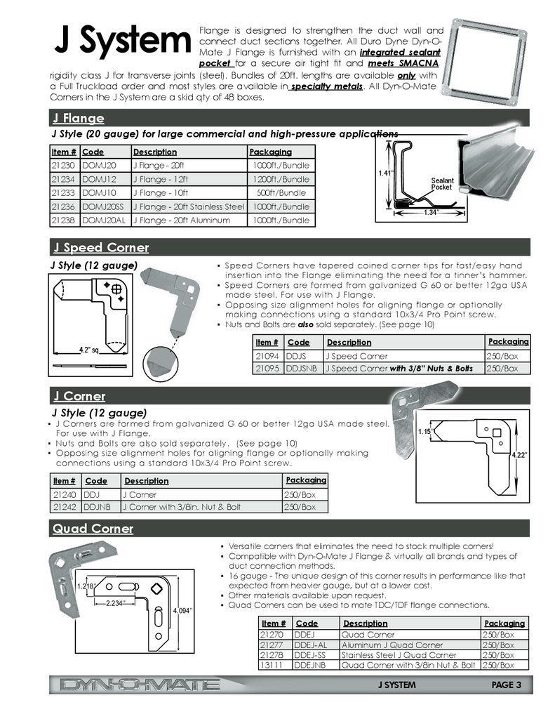
J SystemFlange is designed to strengthen the duct wall and
connect duct sections together. All Duro Dyne Dyn-OMate J Flange is furnished with an integrated sealant
pocket for a secure air tight fit and meets SMACNA
rigidity class J for transverse joints (steel). Bundles of 20ft. lengths are available only with
a Full Truckload order and most styles are available in specialty metals. All Dyn-O-Mate
Corners in the J System are a skid qty of 48 boxes.
J Flange
J Style (20 gauge) for large commercial and high-pressure applications
Item # Code
Description
Packaging
21230 DOMJ20
J Flange - 20ft
1000ft./Bundle
21234 DOMJ12
J Flange - 12ft
1200ft./Bundle
21233 DOMJ10
J Flange - 10ft
500ft/Bundle
21236 DOMJ20SS
J Flange - 20ft Stainless Steel
1000ft./Bundle
21238 DOMJ20AL J Flange - 20ft Aluminum
1.41’’
Sealant
1.34’’
1000ft./Bundle
J Speed Corner
J Style (12 gauge)
▪ Speed Corners have tapered coined corner tips for fast/easy hand
insertion into the Flange eliminating the need for a tinner’s hammer.
▪ Speed Corners are formed from galvanized G 60 or better 12ga USA
made steel. For use with J Flange.
▪ Opposing size alignment holes for aligning flange or optionally
making connections using a standard 10x3/4 Pro Point screw.
▪ Nuts and Bolts are also sold separately. (See page 10)
Item #
4.2” sq
Description
Packaging
J Speed Corner
J Speed Corner with 3/8” Nuts & Bolts
250/Box
250/Box
Code
21094 DDJS
21095 DDJSNB
J Corner
J Style (12 gauge)
▪ J Corners are formed from galvanized G 60 or better 12ga USA made steel.
For use with J Flange.
▪ Nuts and Bolts are also sold separately. (See page 10)
▪ Opposing size alignment holes for aligning flange or optionally making
connections using a standard 10x3/4 Pro Point screw.
Item #
Code
21240 DDJ
21242 DDJNB
Description
Packaging
J Corner
J Corner with 3/8in. Nut & Bolt
250/Box
250/Box
1.15’’
4.22’’
Quad Corner
1.218’’
2.234’’
4.094’’
▪ Versatile corners that eliminates the need to stock multiple corners!
▪ Compatible with Dyn-O-Mate J Flange & virtually all brands and types of
duct connection methods.
▪ 16 gauge - The unique design of this corner results in performance like that
expected from heavier gauge, but at a lower cost.
▪ Other materials available upon request.
▪ Quad Corners can be used to mate TDC/TDF flange connections.
Item #
21270
21277
21278
13111
Code
DDEJ
DDEJ-AL
DDEJ-SS
DDEJNB
Description
Quad Corner
Aluminum J Quad Corner
Stainless Steel J Quad Corner
Quad Corner with 3/8in Nut & Bolt
J SYSTEM
Packaging
250/Box
250/Box
250/Box
250/Box
PAGE 3
4.
Patent Pending and Patent Nos5,342,100; 6,810,570; and 8,172,280
System
EZ Connector® is a revolutionary duct connection system that can save up to 50%+ labor costs in the
field! This innovative system is the first and only corner system on the market that allows the contractor
to fasten a patented locking bolt using a cordless impact driver.
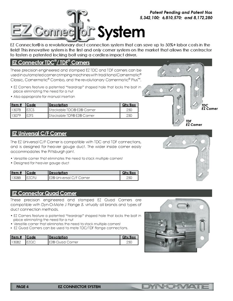
EZ Connector TDC®/ TDF® Corners
These precision engineered and stamped EZ TDC and TDF corners can be
used in automated corner crimping machines with traditional Cornermatic®
Classic, Cornermatic® Combo, and the revolutionary Cornermatic® Plus™.
• EZ Corners feature a patented “teardrop” shaped hole that locks the bolt in
place eliminating the need for a nut
• Also appropriate for manual insertion
Item #
13078
Code
EZCS
Description
Stackable TDC® EZ® Corner
Qty/Box
250
13079
EZFS
Stackable TDF® EZ® Corner
250
TDC
EZ Corner
TDF
EZ Corner
EZ Universal C/F Corner
The EZ Universal C/F Corner is compatible with TDC and TDF connections,
and is designed for heavier gauge duct. The wider inside corner easily
accommodates the Pittsburgh joint.
• Versatile corner that eliminates the need to stock multiple corners!
• Designed for heavier gauge duct
Item #
13088
Code
EZCFU
Description
EZ® Universal C/F Corner
Qty/Box
250
EZ Connector Quad Corner
These precision engineered and stamped EZ Quad Corners are
compatible with Dyn-O-Mate J Flange & virtually all brands and types of
duct connection methods.
• EZ Corners feature a patented “teardrop” shaped hole that locks the bolt in
place eliminating the need for a nut
• Versatile corner that eliminates the need to stock multiple corners!
▪ EZ Quad Corners can be used to mate TDC/TDF flange connections.
Item #
13082
Code
EZQC
PAGE 4
Description
EZ® Quad Corner
EZ CONNECTOR SYSTEM
Qty/Box
250
5.
EZ Connector SystemEZ Connector Bolts
This patented bolt is specifically designed for use with EZ TDC/TDF corners. It acts as an alignment
tool and a locking nut during installation when used with the teardrop EZ Corner.
• Replaces 3/8” carriage bolt, washer and nut at the four corner connections
• Washer built into “extra high” EZ drive head
• Eliminates use of drift-pin and clamps for corner alignment
• Spin-out feature prevents over-torquing and reduces damage to gaskets (leakage at corner
reduced)
• 1-1/2” long version available for larger ductwork, heavier gauge, unique location, special
fitting applications
• 1” bolts available for faster assembly of smaller ductwork
Item #
13070
Code
EZB100B
Description
EZ® Bolt 1 in Only Bulk
Qty/Box
1000
13071
EZB100
EZ® Bolt 1 in Only Bagged
125
13073
EZB112B
EZ® Bolt 1-1/2 in Only Bulk
500
13074
EZB112
EZ® Bolt 1-1/2 in Only Bagged
125
Swivel Impact Nut Driver
The one-piece Swivel Impact Nut Driver features a built in magnet that keeps
the EZ Connector Bolts securely in place during assembly. The head swivels for
added flexibility into tight spaces. Sold separately.
Item #
13077
Code
EZS2
Description
EZ® Swivel Impact Nut Driver
Qty/Box
1
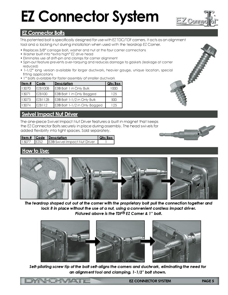
How to Use:
The teardrop shaped cut out of the corner with the proprietary bolt pull the connection together and
lock it in place without the use of a nut, using a convenient cordless impact driver.
Pictured above is the TDF® EZ Corner & 1” bolt.
Self-piloting screw tip of the bolt self-aligns the corners and ductwork, eliminating the need for
an alignment tool and clamping. 1-1/2" bolt shown.
EZ CONNECTOR SYSTEM
PAGE 5
6.
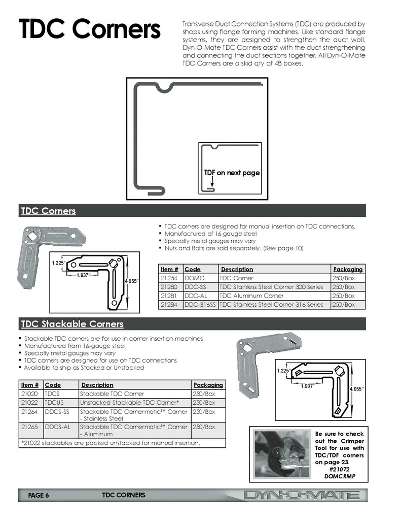
TDC CornersTransverse Duct Connection Systems (TDC) are produced by
shops using flange forming machines. Like standard flange
systems, they are designed to strengthen the duct wall.
Dyn-O-Mate TDC Corners assist with the duct strengthening
and connecting the duct sections together. All Dyn-O-Mate
TDC Corners are a skid qty of 48 boxes.
TDF on next page
TDC Corners
▪ TDC corners are designed for manual insertion on TDC connections.
▪ Manufactured of 16 gauge steel
▪ Specialty metal gauges may vary
▪ Nuts and Bolts are sold separately. (See page 10)
1.225’’
1.937’’
4.055’’
Item #
Code
21254
21280
21281
21284
DOMC
TDC Corner
DDC-SS
TDC Stainless Steel Corner 300 Series
DDC-AL
TDC Aluminum Corner
DDC-316SS TDC Stainless Steel Corner 316 Series
Description
Packaging
250/Box
250/Box
250/Box
250/Box
TDC Stackable Corners
▪ Stackable TDC corners are for use in corner insertion machines
▪ Manufactured from 16-gauge steel
▪ Specialty metal gauges may vary
▪ TDC corners are designed for use on TDC connections
▪ Available to ship as Stacked or Unstacked
Item #
Code
Description
Packaging
21020
21022
21264
TDCS
TDCUS
DDCS-SS
250/Box
250/Box
250/Box
21265
DDCS-AL
Stackable TDC Corner
Unstacked Stackable TDC Corner*
Stackable TDC Cornermatic™ Corner
- Stainless Steel
Stackable TDC Cornermatic™ Corner
- Aluminum
250/Box
*21022 stackables are packed unstacked for manual insertion.
PAGE 6
TDC CORNERS
1.225’’
1.937’’
4.055’’
Be sure to check
out the Crimper
Tool for use with
TDC/TDF corners
on page 23.
#21072
DOMCRMP
7.
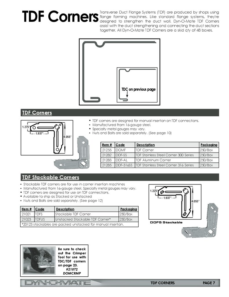
TDF CornersTransverse Duct Flange Systems (TDF) are produced by shops using
flange forming machines. Like standard flange systems, they're
designed to strengthen the duct wall. Dyn-O-Mate TDF Corners
assist with the duct strengthening and connecting the duct sections
together. All Dyn-O-Mate TDF Corners are a skid qty of 48 boxes.
TDC on previous page
TDF Corners
▪ TDF corners are designed for manual insertion on TDF connections.
1.275’’
1.937’’
4.055’’
▪ Manufactured from 16-gauge steel.
▪ Specialty metal gauges may vary.
▪ Nuts and Bolts are sold separately. (See page 10)
Item #
Code
Description
Packaging
21255
21282
21283
21285
DOMF
DDF-SS
DDF-AL
DDF-316SS
TDF Corner
TDF Stainless Steel Corner 300 Series
TDF Aluminum Corner
TDF Stainless Steel Corner 316 Series
250/Box
250/Box
250/Box
250/Box
TDF Stackable Corners
▪ Stackable TDF corners are for use in corner insertion machines
▪ Manufactured from 16-gauge steel. Specialty metal gauges may vary.
▪ TDF corners are designed for use on TDF connections.
▪ Available to ship as Stacked or Unstacked
▪ Nuts and Bolts are sold separately. (See page 12)
Item #
Code
Description
1.225’’
1.937’’
4.055’’
Packaging
21021 TDFS
Stackable TDF Corner
250/Box
21023 TDFUS
Unstacked Stackable TDF Corner*
250/Box
*20123 stackables are packed unstacked for manual insertion.
DDFS Stackable
Be sure to check
out the Crimper
Tool for use with
TDC/TDF corners
on page 23.
#21072
DOMCRMP
TDF CORNERS
PAGE 7
8.
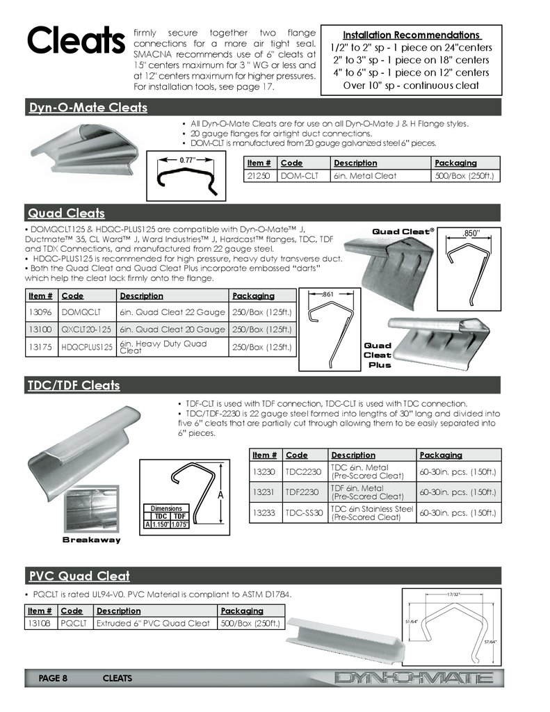
Cleatsfirmly secure together two flange
connections for a more air tight seal.
SMACNA recommends use of 6" cleats at
15" centers maximum for 3 " WG or less and
at 12" centers maximum for higher pressures.
For installation tools, see page 17.
Installation Recommendations
1/2'' to 2'' sp - 1 piece on 24''centers
2'' to 3'' sp - 1 piece on 18'' centers
4'' to 6'' sp - 1 piece on 12'' centers
Over 10'' sp - continuous cleat
Dyn-O-Mate Cleats
▪ All Dyn-O-Mate Cleats are for use on all Dyn-O-Mate J & H Flange styles.
▪ 20 gauge flanges for airtight duct connections.
▪ DOM-CLT is manufactured from 20 gauge galvanized steel 6” pieces.
0.77’’
Item #
Code
Description
Packaging
21250
DOM-CLT
6in. Metal Cleat
500/Box (250ft.)
Quad Cleats
▪ DOMQCLT125 & HDQC-PLUS125 are compatible with Dyn-O-Mate™ J,
Ductmate™ 35, CL Ward™ J, Ward Industries™ J, Hardcast™ flanges, TDC, TDF
and TDX Connections, and manufactured from 22 gauge steel.
▪ HDQC-PLUS125 is recommended for high pressure, heavy duty transverse duct.
▪ Both the Quad Cleat and Quad Cleat Plus incorporate embossed “darts”
which help the cleat lock firmly onto the flange.
Quad Cleat®
.850’’
.861
Item #
Code
Description
Packaging
13096
DOMQCLT
6in. Quad Cleat 22 Gauge 250/Box (125ft.)
13100
QXCLT20-125
6in. Quad Cleat 20 Gauge 250/Box (125ft.)
13175
Heavy Duty Quad
HDQCPLUS125 6in.
Cleat
250/Box (125ft.)
Quad
Cleat
Plus
TDC/TDF Cleats
▪ TDF-CLT is used with TDF connection, TDC-CLT is used with TDC connection.
▪ TDC/TDF-2230 is 22 gauge steel formed into lengths of 30” long and divided into
five 6” cleats that are partially cut through allowing them to be easily separated into
6” pieces.
Item #
A
Dimensions
TDC TDF
A 1.150'' 1.075''
Code
Description
Packaging
13230
TDC2230
TDC 6in. Metal
(Pre-Scored Cleat)
60-30in. pcs. (150ft.)
13231
TDF2230
TDF 6in. Metal
(Pre-Scored Cleat)
60-30in. pcs. (150ft.)
13233
TDC-SS30
TDC 6in Stainless Steel 60-30in. pcs. (150ft.)
(Pre-Scored Cleat)
Breakaway
PVC Quad Cleat
▪ PQCLT is rated UL94-V0. PVC Material is compliant to ASTM D1784.
Item #
Code
Description
Packaging
13108
PQCLT
Extruded 6" PVC Quad Cleat
500/Box (250ft.)
17/32"
51/64"
57/64"
PAGE 8
CLEATS
9.
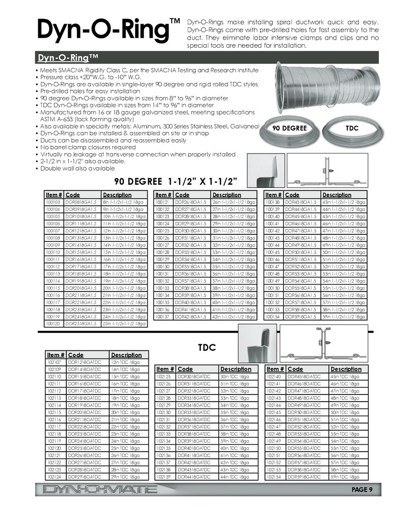
Dyn-O-Ringmake installing spiral ductwork quick and easy.
™ Dyn-O-Rings
Dyn-O-Rings come with pre-drilled holes for fast assembly to the
duct. They eliminate labor intensive clamps and clips and no
special tools are needed for installation.
Dyn-O-Ring™
• Meets SMACNA Rigidity Class C, per the SMACNA Testing and Research Institute
• Pressure class +20”W.G. to -10” W.G.
• Dyn-O-Rings are available in single-layer 90 degree and rigid rolled TDC styles
• Pre-drilled holes for easy installation
• 90 degree Dyn-O-Rings available in sizes from 8” to 96” in diameter
• TDC Dyn-O-Rings available in sizes from 14” to 96” in diameter
• Manufactured from 16 or 18 gauge galvanized steel, meeting specifications
ASTM A-653 (lock forming quality)
• Also available in specialty metals: Aluminum, 300 Series Stainless Steel, Galvaneal
• Dyn-O-Rings can be installed & assembled on site or in shop
• Ducts can be disassembled and reassembled easily
• No barrel clamp closures required
• Virtually no leakage at transverse connection when properly installed
• 2-1/2 in x 1-1/2" also available.
• Double wall also available
90 DEGREE
TDC
90 DEGREE 1-1/2” X 1-1/2”
Item # Code
Description
Item # Code
Description
Item # Code
Description
100103
8in 1-1/2x1-1/2 18ga
100121
26in 1-1/2x1-1/2 18ga
100138
43in 1-1/2x1-1/2 18ga
DOR0818GA1.5
DOR2618GA1.5
DOR4318GA1.5
100104
DOR0918GA1.5
9in 1-1/2x1-1/2 18ga
100122
DOR2718GA1.5
27in 1-1/2x1-1/2 18ga
100139
DOR4418GA1.5
44in 1-1/2x1-1/2 18ga
100105
DOR1018GA1.5
10in 1-1/2x1-1/2 18ga
100123
DOR2818GA1.5
28in 1-1/2x1-1/2 18ga
100140
DOR4518GA1.5
45in 1-1/2x1-1/2 18ga
100106
DOR1118GA1.5
11in 1-1/2x1-1/2 18ga
100124
DOR2918GA1.5
29in 1-1/2x1-1/2 18ga
100141
DOR4618GA1.5
46in 1-1/2x1-1/2 18ga
100107
DOR1218GA1.5
12in 1-1/2x1-1/2 18ga
100125
DOR3018GA1.5
30in 1-1/2x1-1/2 18ga
100142
DOR4718GA1.5
47in 1-1/2x1-1/2 18ga
100108
DOR1318GA1.5
13in 1-1/2x1-1/2 18ga
100126
DOR3118GA1.5
31in 1-1/2x1-1/2 18ga
100143
DOR4818GA1.5
48in 1-1/2x1-1/2 18ga
100109
DOR1418GA1.5
14in 1-1/2x1-1/2 18ga
100127
DOR3218GA1.5
32in 1-1/2x1-1/2 18ga
100144
DOR4918GA1.5
49in 1-1/2x1-1/2 18ga
100110
DOR1518GA1.5
15in 1-1/2x1-1/2 18ga
100128
DOR3318GA1.5
33in 1-1/2x1-1/2 18ga
100145
DOR5018GA1.5
50in 1-1/2x1-1/2 18ga
100111
DOR1618GA1.5
16in 1-1/2x1-1/2 18ga
100129
DOR3418GA1.5
34in 1-1/2x1-1/2 18ga
100146
DOR5118GA1.5
51in 1-1/2x1-1/2 18ga
100112
DOR1718GA1.5
17in 1-1/2x1-1/2 18ga
100130
DOR3518GA1.5
35in 1-1/2x1-1/2 18ga
100147
DOR5218GA1.5
52in 1-1/2x1-1/2 18ga
100113
DOR1818GA1.5
18in 1-1/2x1-1/2 18ga
100131
DOR3618GA1.5
36in 1-1/2x1-1/2 18ga
100148
DOR5318GA1.5
53in 1-1/2x1-1/2 18ga
100114
DOR1918GA1.5
19in 1-1/2x1-1/2 18ga
100132
DOR3718GA1.5
37in 1-1/2x1-1/2 18ga
100149
DOR5418GA1.5
54in 1-1/2x1-1/2 18ga
100115
DOR2018GA1.5
20in 1-1/2x1-1/2 18ga
100133
DOR3818GA1.5
38in 1-1/2x1-1/2 18ga
100150
DOR5518GA1.5
55in 1-1/2x1-1/2 18ga
100116
DOR2118GA1.5
21in 1-1/2x1-1/2 18ga
100134
DOR3918GA1.5
39in 1-1/2x1-1/2 18ga
100151
DOR5618GA1.5
56in 1-1/2x1-1/2 18ga
100117
DOR2218GA1.5
22in 1-1/2x1-1/2 18ga
100135
DOR4018GA1.5
40in 1-1/2x1-1/2 18ga
100152
DOR5718GA1.5
57in 1-1/2x1-1/2 18ga
100118
DOR2318GA1.5
23in 1-1/2x1-1/2 18ga
100136
DOR4118GA1.5
41in 1-1/2x1-1/2 18ga
100153
DOR5818GA1.5
58in 1-1/2x1-1/2 18ga
100119
DOR2418GA1.5
24in 1-1/2x1-1/2 18ga
100137
DOR4218GA1.5
42in 1-1/2x1-1/2 18ga
100154
DOR5918GA1.5
59in 1-1/2x1-1/2 18ga
100120
DOR2518GA1.5
25in 1-1/2x1-1/2 18ga
TDC
Item # Code
Description
102107
DOR1218GATDC
12in TDC 18ga
102109
DOR1418GATDC
14in TDC 18ga
Item # Code
Description
Item # Code
Description
102110
DOR1518GATDC
15in TDC 18ga
102125
DOR3018GATDC
30in TDC 18ga
102140
DOR4518GATDC
45in TDC 18ga
102111
DOR1618GATDC
16in TDC 18ga
102126
DOR3118GATDC
31in TDC 18ga
102141
DOR4618GATDC
46in TDC 18ga
102112
DOR1718GATDC
17in TDC 18ga
102127
DOR3218GATDC
32in TDC 18ga
102142
DOR4718GATDC
47in TDC 18ga
102113
DOR1818GATDC
18in TDC 18ga
102128
DOR3318GATDC
33in TDC 18ga
102143
DOR4818GATDC
48in TDC 18ga
102114
DOR1918GATDC
19in TDC 18ga
102129
DOR3418GATDC
34in TDC 18ga
102144
DOR4918GATDC
49in TDC 18ga
102115
DOR2018GATDC
20in TDC 18ga
102130
DOR3518GATDC
35in TDC 18ga
102145
DOR5018GATDC
50in TDC 18ga
102116
DOR2118GATDC
21in TDC 18ga
102131
DOR3618GATDC
36in TDC 18ga
102146
DOR5118GATDC
51in TDC 18ga
102117
DOR2218GATDC
22in TDC 18ga
102132
DOR3718GATDC
37in TDC 18ga
102147
DOR5218GATDC
52in TDC 18ga
102118
DOR2318GATDC
23in TDC 18ga
102133
DOR3818GATDC
38in TDC 18ga
102148
DOR5318GATDC
53in TDC 18ga
102119
DOR2418GATDC
24in TDC 18ga
102134
DOR3918GATDC
39in TDC 18ga
102149
DOR5418GATDC
54in TDC 18ga
102120
DOR2518GATDC
25in TDC 18ga
102135
DOR4018GATDC
40in TDC 18ga
102150
DOR5518GATDC
55in TDC 18ga
102121
DOR2618GATDC
26in TDC 18ga
102136
DOR4118GATDC
41in TDC 18ga
102151
DOR5618GATDC
56in TDC 18ga
102122
DOR2718GATDC
27in TDC 18ga
102137
DOR4218GATDC
42in TDC 18ga
102152
DOR5718GATDC
57in TDC 18ga
102123
DOR2818GATDC
28in TDC 18ga
102138
DOR4318GATDC
43in TDC 18ga
102153
DOR5818GATDC
58in TDC 18ga
102124
DOR2918GATDC
29in TDC 18ga
102139
DOR4418GATDC
44in TDC 18ga
102154
DOR5918GATDC
59in TDC 18ga
PAGE 9
10.
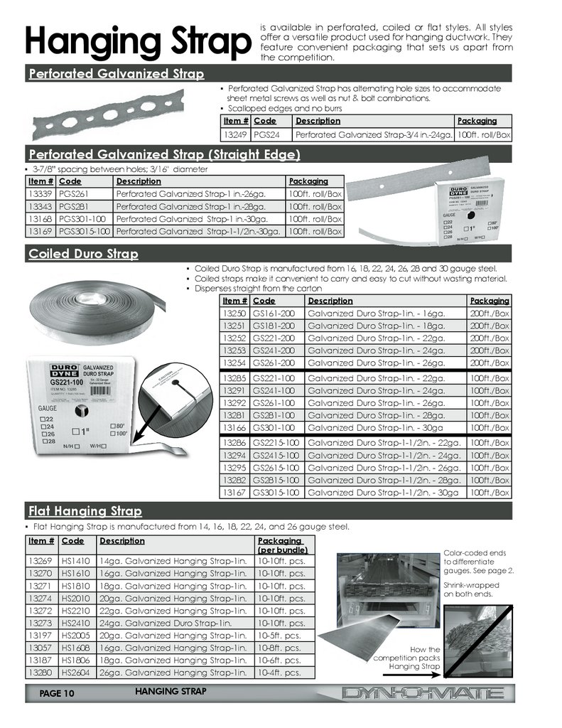
Hanging Strapis available in perforated, coiled or flat styles. All styles
offer a versatile product used for hanging ductwork. They
feature convenient packaging that sets us apart from
the competition.
Perforated Galvanized Strap
▪ Perforated Galvanized Strap has alternating hole sizes to accommodate
sheet metal screws as well as nut & bolt combinations.
▪ Scalloped edges and no burrs
Item # Code
Description
Packaging
13249 PGS24
Perforated Galvanized Strap-3/4 in.-24ga. 100ft. roll/Box
Perforated Galvanized Strap (Straight Edge)
▪ 3-7/8” spacing between holes; 3/16" diameter
Item # Code
Description
Packaging
13339
13343
13168
13169
100ft. roll/Box
100ft. roll/Box
100ft. roll/Box
100ft. roll/Box
PGS261
PGS281
PGS301-100
PGS3015-100
Perforated Galvanized Strap-1 in.-26ga.
Perforated Galvanized Strap-1 in.-28ga.
Perforated Galvanized Strap-1 in.-30ga.
Perforated Galvanized Strap-1-1/2in.-30ga.
Coiled Duro Strap
▪ Coiled Duro Strap is manufactured from 16, 18, 22, 24, 26, 28 and 30 gauge steel.
▪ Coiled straps make it convenient to carry and easy to cut without wasting material.
▪ Dispenses straight from the carton
Item # Code
Description
Packaging
13250
13251
13252
13253
13254
GS161-200
GS181-200
GS221-200
GS241-200
GS261-200
Galvanized Duro Strap-1in. - 16ga.
Galvanized Duro Strap-1in. - 18ga.
Galvanized Duro Strap-1in. - 22ga.
Galvanized Duro Strap-1in. - 24ga.
Galvanized Duro Strap-1in. - 26ga.
200ft./Box
200ft./Box
200ft./Box
200ft./Box
200ft./Box
13285
13291
13292
13281
13166
GS221-100
GS241-100
GS261-100
GS281-100
GS301-100
Galvanized Duro Strap-1in. - 22ga.
Galvanized Duro Strap-1in. - 24ga.
Galvanized Duro Strap-1in. - 26ga.
Galvanized Duro Strap-1in. - 28ga.
Galvanized Duro Strap-1in. - 30ga
100ft./Box
100ft./Box
100ft./Box
100ft./Box
100ft./Box
13286
13294
13295
13282
13167
GS2215-100
GS2415-100
GS2615-100
GS2815-100
GS3015-100
Galvanized Duro Strap-1-1/2in. - 22ga.
Galvanized Duro Strap-1-1/2in. - 24ga.
Galvanized Duro Strap-1-1/2in. - 26ga.
Galvanized Duro Strap-1-1/2in. - 28ga.
Galvanized Duro Strap-1-1/2in. - 30ga
100ft./Box
100ft./Box
100ft./Box
100ft./Box
100ft./Box
Flat Hanging Strap
▪ Flat Hanging Strap is manufactured from 14, 16, 18, 22, 24, and 26 gauge steel.
Item # Code
Description
13269
13270
13271
13274
13272
13273
13197
13057
13187
13280
14ga. Galvanized Hanging Strap-1in.
16ga. Galvanized Hanging Strap-1in.
18ga. Galvanized Hanging Strap-1in.
20ga. Galvanized Hanging Strap-1in.
22ga. Galvanized Hanging Strap-1in.
24ga. Galvanized Duro Strap-1in.
20ga. Galvanized Hanging Strap-1in.
16ga. Galvanized Hanging Strap-1in.
18ga. Galvanized Hanging Strap-1in.
26ga. Galvanized Hanging Strap-1in.
HS1410
HS1610
HS1810
HS2010
HS2210
HS2410
HS2005
HS1608
HS1806
HS2604
PAGE 10
HANGING STRAP
Packaging
(per bundle)
10-10ft. pcs.
10-10ft. pcs.
10-10ft. pcs.
10-10ft. pcs.
10-10ft. pcs.
10-10ft. pcs.
10-5ft. pcs.
10-8ft. pcs.
10-6ft. pcs.
10-4ft. pcs.
Color-coded ends
to differentiate
gauges. See page 2.
Shrink-wrapped
on both ends.
How the
competition packs
Hanging Strap
11.
Hanging Strap (continued)Perforated Plastic Strap
Perforated Plastic 3/4” Hanging Strap is UV Resistant - ASTM G154-12a. It is nonabrasive and for all light HVAC hanging and strapping needs. It is bright yellow
color for easy identification.
Item # Code
Description
Packaging
13182 PPF34-100UV
Perforated Plastic
Hanging Strap 3/4in-100ft
100ft. roll/
30 rolls per box
Dyn-O-Strut & Accessories
™
Hanging ductwork, equipment, wiring trays or other building components requires secure structural assemblies.
These assemblies are comprised of support members attached to building anchor points with fasteners. The
support members are often lengths of strut or angle iron. The fastener frequently is threaded rod combined with
washers and nuts.
1/2"
9/16"x1-1/8" SLOT
2"
(TYP)
Dyn-O-Strut™
• *Pre-Galvanized ASTM A-653 grade 33 steel
sheet zinc coated by hot dip process
• Cold-formed to size from low carbon strip steel
• Slotted at 2‘’ centers
• Specialty metals available upon request
7/8"
10FT
DYN-O-STRUT
1-5/8"
DYN-O-STRUT
1-5/8"
1/2"
9/16"x1-1/8" SLOT
2"
(TYP)
Item #
13045
13049
13047
Code
DS1210-158
DS1410-158
DS1410-1316
Description
1-5/8x1-5/8x10ft 12 GA Slotted Dyn-O-Strut - Deep
1-5/8x1-5/8x10ft 14 GA Slotted Dyn-O-Strut - Deep
13/16x1-5/8x10ft 14 GA Slotted Dyn-O-Strut - Shallow
13125
13126
13127
DS1220-158 1-5/8x1-5/8x20ft 12 GA Slotted Dyn-O-Strut - Deep
DS1420-158 1-5/8x1-5/8x20ft 14 GA Slotted Dyn-O-Strut - Deep
DS1420-1316 13/16x1-5/8x20ft 14 GA Slotted Dyn-O-Strut - Shallow
10FT
DYN-O-STRUT
Length
10’
10’
10’
Packaging
500ft/Bundle
500ft/Bundle
500ft/Bundle
20’
20’
20’
500ft/Bundle
500ft/Bundle
1000ft/Bundle
DYN-O-STRUT
7/8"
13/16"
1-5/8"
Accessories
Slotted Strut is a common product used in Commercial Construction. With
slotted holes at 2‘’ centers, it allows for easy use with threaded rod and an
assortment of threaded rod accessories that can engage and secure to
the strut.
SW38
SB90
S38
SN38
Item #
13101
13102
13103
13104
Code
SW38
S38
SN38
SB90
Description
3/8in Square Washer
Strut Nut without Spring
Strut Nut with Spring
90 Degree Strut Bracket
DYN-O-STRUT
Packaging
100
100
100
50
PAGE 11
12.
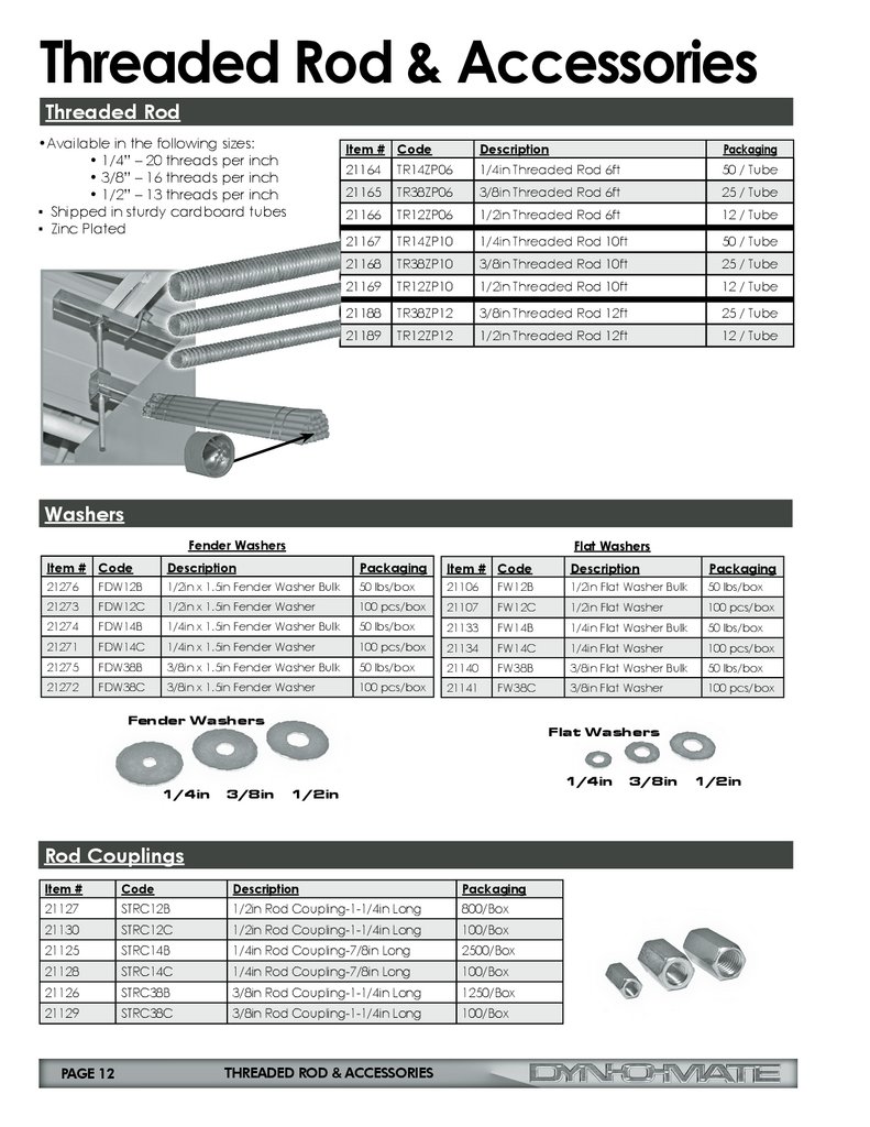
Threaded Rod & AccessoriesThreaded Rod
•Available in the following sizes:
• 1/4” – 20 threads per inch
• 3/8” – 16 threads per inch
• 1/2” – 13 threads per inch
▪ Shipped in sturdy cardboard tubes
▪ Zinc Plated
Item # Code
Description
Packaging
21164
TR14ZP06
1/4in Threaded Rod 6ft
50 / Tube
21165
TR38ZP06
3/8in Threaded Rod 6ft
25 / Tube
21166
TR12ZP06
1/2in Threaded Rod 6ft
12 / Tube
21167
TR14ZP10
1/4in Threaded Rod 10ft
50 / Tube
21168
TR38ZP10
3/8in Threaded Rod 10ft
25 / Tube
21169
TR12ZP10
1/2in Threaded Rod 10ft
12 / Tube
21188
TR38ZP12
3/8in Threaded Rod 12ft
25 / Tube
21189
TR12ZP12
1/2in Threaded Rod 12ft
12 / Tube
Washers
Fender Washers
Flat Washers
Item # Code
Description
Packaging
Item # Code
Description
Packaging
21276
FDW12B
1/2in x 1.5in Fender Washer Bulk
50 lbs/box
21106
FW12B
1/2in Flat Washer Bulk
50 lbs/box
21273
FDW12C
1/2in x 1.5in Fender Washer
100 pcs/box
21107
FW12C
1/2in Flat Washer
100 pcs/box
21274
FDW14B
1/4in x 1.5in Fender Washer Bulk
50 lbs/box
21133
FW14B
1/4in Flat Washer Bulk
50 lbs/box
21271
FDW14C
1/4in x 1.5in Fender Washer
100 pcs/box
21134
FW14C
1/4in Flat Washer
100 pcs/box
21275
FDW38B
3/8in x 1.5in Fender Washer Bulk
50 lbs/box
21140
FW38B
3/8in Flat Washer Bulk
50 lbs/box
21272
FDW38C
3/8in x 1.5in Fender Washer
100 pcs/box
21141
FW38C
3/8in Flat Washer
100 pcs/box
Fender Washers
1/4in
3/8in
Flat Washers
1/4in
1/2in
Rod Couplings
Item #
Code
Description
Packaging
21127
STRC12B
1/2in Rod Coupling-1-1/4in Long
800/Box
21130
STRC12C
1/2in Rod Coupling-1-1/4in Long
100/Box
21125
STRC14B
1/4in Rod Coupling-7/8in Long
2500/Box
21128
STRC14C
1/4in Rod Coupling-7/8in Long
100/Box
21126
STRC38B
3/8in Rod Coupling-1-1/4in Long
1250/Box
21129
STRC38C
3/8in Rod Coupling-1-1/4in Long
100/Box
PAGE 12
THREADED ROD & ACCESSORIES
3/8in
1/2in
13.
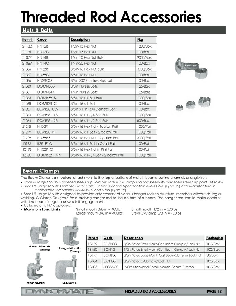
Threaded Rod AccessoriesNuts & Bolts
Item #
Code
Description
Pkg
21132
HN12B
1/2in-13 Hex Nut
1800/Box
21131
HN12C
1/2in-13 Hex Nut
100/Box
21077
HN14B
1/4in-20 Hex Nut Bulk
9000/Box
21069
HN14C
1/4in-20 Hex Nut
100/Box
21066
HN38B
3/8in-16 Hex Nut Bulk
3000/Box
21067
HN38C
3/8in-16 Hex Nut
100/Box
21086
HN38CSS
3/8in 302 Stainless Hex Nut
100/Box
21060
DOMNB38
3/8in Nuts & Bolts
125/Bag
21061
DOMNB14
1/4in Nuts & Bolts
125/Bag
21065
DOMB381B
3/8in-16 x 1 Bolt Bulk
1000/Box
21068
DOMB381C
3/8in-16 x 1 Bolt
100/Box
21087
DOMB381CSS
3/8in x 1 in. 304 Stainless Bolt
100/Box
21063
DOMB38114B
3/8in-16 x 1-1/4 Bolt Bulk
1000/Box
21064
DOMB38112B
3/8in-16 x 1-1/2 Bolt Bulk
800/Box
21218
HN38P1
3/8in-16 Hex Nut - 1gallon Pail
1000/Pail
21219
DOMB381P1
3/8in-16 x 1 Bolt - 2 gallon Pail
1000/Pail
21229
HN38P3
3/8in-16 Hex Nut - 2 gallon Pail
3000/Pail
13192
B381P1C
3/8in-16 x 1 Bolt in Quart Pail
100/Pail
13196
HN38P1C
3/8in-16 Hex Nut in Pint Pail
100/Pail
13186
DOMB38114P1
3/8in-16 x 1-1/4 Bolt - 2 gallon Pail
1000/Pail
Beam Clamps
The Beam Clamp is a structural attachment to the top or bottom of metal I-beams, purlins, channel, or angle iron.
• Small & Large Mouth: Hardened steel Cup Point Set screw. C-Clamp: Carbon steel with hardened steel cup point set screw
• Small & Large Mouth Complies with: Cast Clamps: Federal Specification A-A-1192A (Type 19) and Manufacturers’
Standardization Society ANSI/SP-69 and SP58 (Type 19).
• Small & Large Mouth designed to provide attachment of various hanger rods to structural members without drilling or
welding. C-Clamp Designed for attaching hanger rod to the bottom of a beam. The hanger rod should make contact
with the beam flange to ensure full engagement.
• UL Listed and FM approved.
• Maximum Load Limits:
Small mouth 3/8 in = 400lbs
Small mouth 1/2 in = 500lbs
Large mouth 3/8 in = 400lbs
Steel C-Clamp 3/8 in = 400lbs
Small Mouth
Clamp
SBCSN38
Large Mouth
Clamp
Item #
Code
Description
Packaging
13179
BC5N38
3/8in Plated Small Mouth Cast Beam-Clamp w/ Lock Nut
100/Box
13180
BCN12
1/2in Plated Small Mouth Cast Beam-Clamp w/ Lock Nut
100/Box
13177
BCNL38
3/8in Plated Large Mouth Cast Beam-Clamp w/ Lock Nut
50/Box
13184
CCN38
3/8in Plated C-Clamp w/ Lock Nut
100/Box
13105
SBCSN38
3/8in Stamped Small Mouth Beam Clamp
100/Box
THREADED ROD ACCESSORIES
PAGE 13
C-Clamp
14.
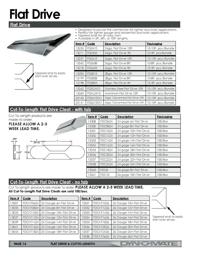
Flat DriveFlat Drive
▪ Designed to secure the connection for lighter ductwork applications.
▪ Perfect for lighter gauge and residential ductwork applications.
▪ Tapered ends for an easy start.
▪ Available in 5ft., 8ft., or 10ft. lengths.
Tapered end to easily
start over drives.
Item # Code
Description
Packaging
13255
FD2410
24ga. Flat Drive 10ft.
10-10ft. pcs./Bundle
13211
FD2405
24ga. Flat Drive 5ft.
10-5ft. pcs/Bundle
13257
FD2610
26ga. Flat Drive 10ft.
10-10ft. pcs./Bundle
13342
FD2608
26ga. Flat Drive 8ft.
10-8ft. pcs./Bundle
13218
FD2605
26ga. Flat Drive 5ft.
10-5ft. pcs./Bundle
13200
FD2810
28ga. Flat Drive 10ft.
10-10ft. pcs./Bundle
13199
FD2808
28ga. Flat Drive 8ft.
10-8ft. pcs./Bundle
13198
FD2805
28ga. Flat Drive 5ft.
10-5ft. pcs./Bundle
13262
FDSS2410
Stainless Steel Flat Drive 10ft.
10-10ft. pcs./Bundle
13260
FDAL2410
Aluminum Flat Drive 10ft.
10-10ft. pcs./Bundle
25140
FD2410GN
24ga. Galvanneal Flat Drive 10ft. 10-10ft. pcs./Bundle
25141
FD2610GN
26ga. Galvanneal Flat Drive 10ft. 10-10ft. pcs./Bundle
1-3/64"
'L'
3/32"
Cut-To-Length Flat Drive Cleat - with tab
Cut To Length products are
made to order.
Item #
Code
Description
Packaging
PLEASE ALLOW A 2-3
WEEK LEAD TIME.
13308
FDC0624
24 gage 6in Flat Drive
100/Box
13350
FDC0824
24 gage 8in Flat Drive
100/Box
.094"
1.047"
1"
(2PLS)
'L'
1"DIA
13351
FDC1024
24 gage 10in Flat Drive
100/Box
13352
FDC1224
24 gage 12in Flat Drive
100/Box
13353
FDC1424
24 gage 14in Flat Drive
100/Box
13354
FDC1624
24 gage 16in Flat Drive
100/Box
13355
FDC1824
24 gage 18in Flat Drive
100/Box
13356
FDC2024
24 gage 20in Flat Drive
100/Box
13357
FDC2224
24 gage 22in Flat Drive
100/Box
13358
FDC2424
24 gage 24in Flat Drive
100/Box
13340
FDC8
26 gage 8in Flat Drive
100/Box
13341
FDC10
26 gage 10in Flat Drive
100/Box
Cut-To-Length Flat Drive Cleat - no tab
Cut To Length products are made to order. PLEASE ALLOW A 2-3 WEEK LEAD TIME.
All Cut-To-Length Flat Drive Cleats are sold 100/box.
Item #
Code
Item # Code
Description
13307
FDCNT0624 24 Gauge 6in Flat Drive
13331
FDCNT1026
26 Gauge 10in Flat Drive
13033
FDCNT0824 24 Gauge 8in Flat Drive
13332
FDCNT1226
26 Gauge 12in Flat Drive
13035
FDCNT1024 24 Gauge 10in Flat Drive
13333
FDCNT1426
26 Gauge 14in Flat Drive
13037
FDCNT1224 24 Gauge 12in Flat Drive
13334
FDCNT1626
26 Gauge 16in Flat Drive
13039
FDCNT1424 24 Gauge 14in Flat Drive
13335
FDCNT1826
26 Gauge 18in Flat Drive
13041
FDCNT1624 24 Gauge 16in Flat Drive
13336
FDCNT2026
26 Gauge 20in Flat Drive
13043
FDCNT1824 24 Gauge 18in Flat Drive
13337
FDCNT2426
26 Gauge 24in Flat Drive
13338
FDCNT3626
26 Gauge 36in Flat Drive
3/32"
'L'
FLAT DRIVE & CUT-TO-LENGTH
1-3/64"
PAGE 14
Description
Tapered end to easily
start over drives.
15.
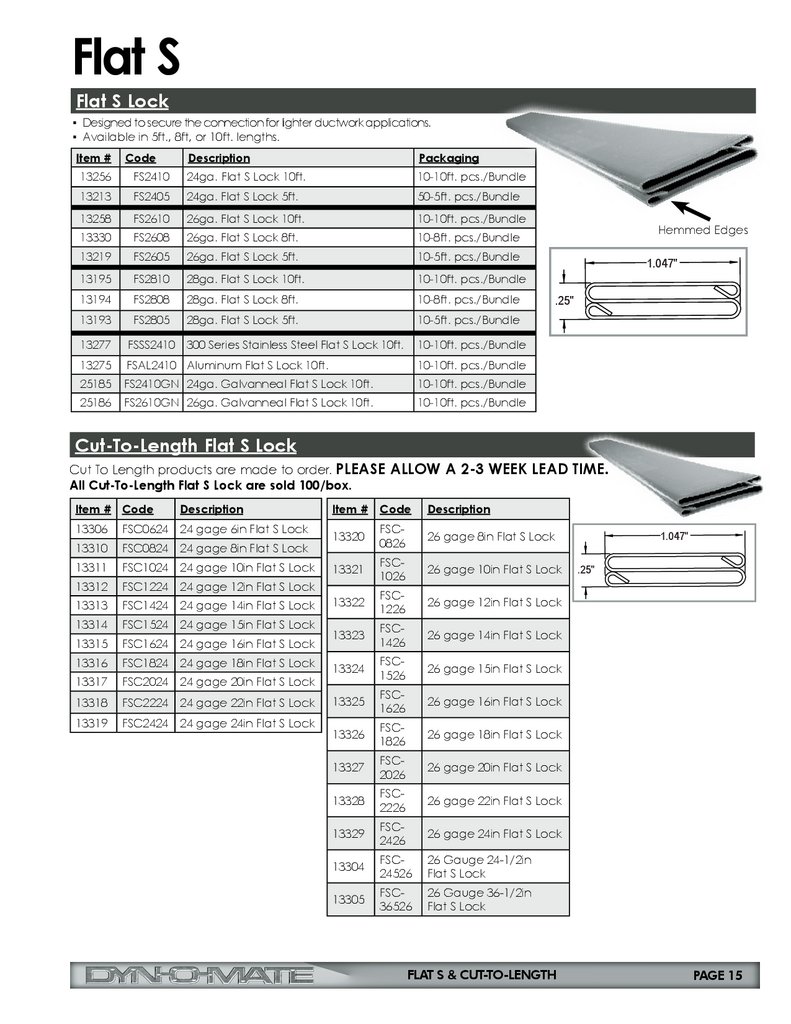
Flat SFlat S Lock
▪ Designed to secure the connection for lighter ductwork applications.
▪ Available in 5ft., 8ft, or 10ft. lengths.
Item #
Description
Packaging
13256
Code
FS2410
24ga. Flat S Lock 10ft.
10-10ft. pcs./Bundle
13213
FS2405
24ga. Flat S Lock 5ft.
50-5ft. pcs./Bundle
13258
FS2610
26ga. Flat S Lock 10ft.
10-10ft. pcs./Bundle
13330
FS2608
26ga. Flat S Lock 8ft.
10-8ft. pcs./Bundle
13219
FS2605
26ga. Flat S Lock 5ft.
10-5ft. pcs./Bundle
13195
FS2810
28ga. Flat S Lock 10ft.
10-10ft. pcs./Bundle
13194
FS2808
28ga. Flat S Lock 8ft.
10-8ft. pcs./Bundle
13193
FS2805
28ga. Flat S Lock 5ft.
10-5ft. pcs./Bundle
13277
FSSS2410 300 Series Stainless Steel Flat S Lock 10ft.
10-10ft. pcs./Bundle
13275
FSAL2410 Aluminum Flat S Lock 10ft.
10-10ft. pcs./Bundle
25185
FS2410GN 24ga. Galvanneal Flat S Lock 10ft.
10-10ft. pcs./Bundle
25186
FS2610GN 26ga. Galvanneal Flat S Lock 10ft.
10-10ft. pcs./Bundle
Hemmed Edges
1.047"
.25"
Cut-To-Length Flat S Lock
Cut To Length products are made to order. PLEASE ALLOW A 2-3 WEEK LEAD TIME.
All Cut-To-Length Flat S Lock are sold 100/box.
Item # Code
Description
13306
FSC0624 24 gage 6in Flat S Lock
13310
FSC0824 24 gage 8in Flat S Lock
13311
FSC1024 24 gage 10in Flat S Lock
13312
FSC1224 24 gage 12in Flat S Lock
13313
FSC1424 24 gage 14in Flat S Lock
13314
FSC1524 24 gage 15in Flat S Lock
13315
FSC1624 24 gage 16in Flat S Lock
13316
FSC1824 24 gage 18in Flat S Lock
13317
FSC2024 24 gage 20in Flat S Lock
13318
FSC2224 24 gage 22in Flat S Lock
13319
FSC2424 24 gage 24in Flat S Lock
Item #
Code
Description
13320
FSC0826
26 gage 8in Flat S Lock
13321
FSC1026
26 gage 10in Flat S Lock
13322
FSC1226
26 gage 12in Flat S Lock
13323
FSC1426
26 gage 14in Flat S Lock
13324
FSC1526
26 gage 15in Flat S Lock
13325
FSC1626
26 gage 16in Flat S Lock
13326
FSC1826
26 gage 18in Flat S Lock
13327
FSC2026
26 gage 20in Flat S Lock
13328
FSC2226
26 gage 22in Flat S Lock
13329
FSC2426
26 gage 24in Flat S Lock
13304
FSC24526
26 Gauge 24-1/2in
Flat S Lock
13305
FSC36526
26 Gauge 36-1/2in
Flat S Lock
FLAT S & CUT-TO-LENGTH
1.047"
.25"
PAGE 15
16.
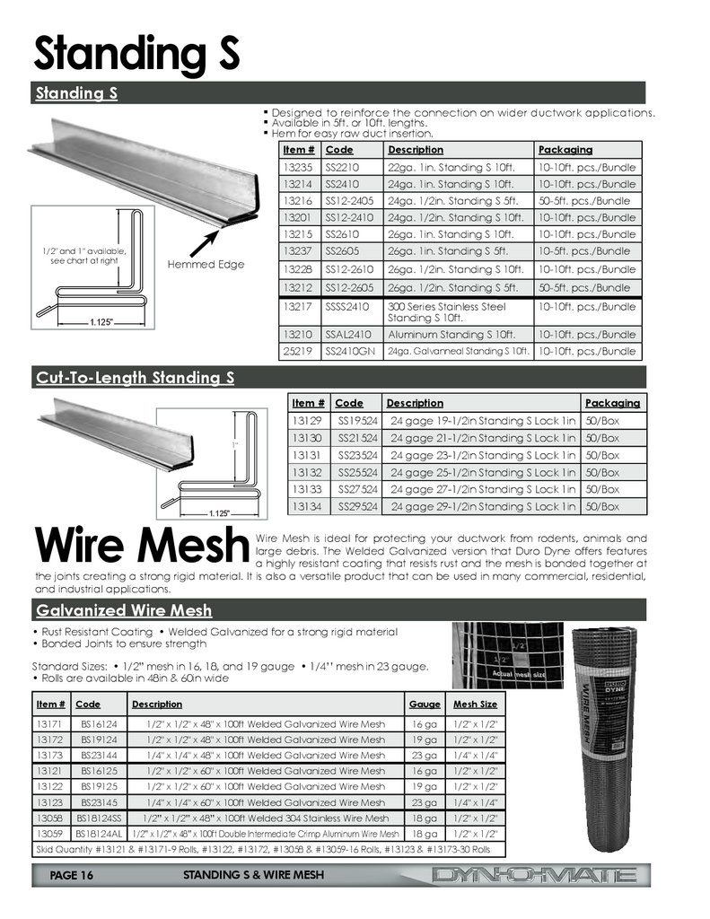
Standing SStanding S
1/2" and 1" available,
see chart at right
▪ Designed to reinforce the connection on wider ductwork applications.
▪ Available in 5ft. or 10ft. lengths.
▪ Hem for easy raw duct insertion.
Hemmed Edge
Item #
Code
Description
Packaging
13235
SS2210
22ga. 1in. Standing S 10ft.
10-10ft. pcs./Bundle
13214
SS2410
24ga. 1in. Standing S 10ft.
10-10ft. pcs./Bundle
13216
SS12-2405
24ga. 1/2in. Standing S 5ft.
50-5ft. pcs./Bundle
13201
SS12-2410
24ga. 1/2in. Standing S 10ft.
10-10ft. pcs./Bundle
13215
SS2610
26ga. 1in. Standing S 10ft.
10-10ft. pcs./Bundle
13237
SS2605
26ga. 1in. Standing S 5ft.
10-5ft. pcs./Bundle
13228
SS12-2610
26ga. 1/2in. Standing S 10ft.
10-10ft. pcs./Bundle
13212
SS12-2605
26ga. 1/2in. Standing S 5ft.
50-5ft. pcs./Bundle
13217
SSSS2410
300 Series Stainless Steel
Standing S 10ft.
10-10ft. pcs./Bundle
13210
SSAL2410
Aluminum Standing S 10ft.
10-10ft. pcs./Bundle
25219
SS2410GN
24ga. Galvanneal Standing S 10ft. 10-10ft. pcs./Bundle
1.125"
Cut-To-Length Standing S
1"
1.125"
Item #
Code
Description
Packaging
13129
SS19524
24 gage 19-1/2in Standing S Lock 1in 50/Box
13130
SS21524
24 gage 21-1/2in Standing S Lock 1in 50/Box
13131
SS23524
24 gage 23-1/2in Standing S Lock 1in 50/Box
13132
SS25524
24 gage 25-1/2in Standing S Lock 1in 50/Box
13133
SS27524
24 gage 27-1/2in Standing S Lock 1in 50/Box
13134
SS29524
24 gage 29-1/2in Standing S Lock 1in 50/Box
Wire Mesh
Wire Mesh is ideal for protecting your ductwork from rodents, animals and
large debris. The Welded Galvanized version that Duro Dyne offers features
a highly resistant coating that resists rust and the mesh is bonded together at
the joints creating a strong rigid material. It is also a versatile product that can be used in many commercial, residential,
and industrial applications.
Galvanized Wire Mesh
• Rust Resistant Coating • Welded Galvanized for a strong rigid material
• Bonded Joints to ensure strength
Standard Sizes: • 1/2” mesh in 16, 18, and 19 gauge • 1/4’’ mesh in 23 gauge.
• Rolls are available in 48in & 60in wide
Item #
Code
13171
BS16124
13172
13173
Description
Gauge
Mesh Size
1/2" x 1/2" x 48" x 100ft Welded Galvanized Wire Mesh
16 ga
1/2" x 1/2"
BS19124
1/2" x 1/2" x 48" x 100ft Welded Galvanized Wire Mesh
19 ga
1/2" x 1/2"
BS23144
1/4" x 1/4" x 48" x 100ft Welded Galvanized Wire Mesh
23 ga
1/4" x 1/4"
13121
BS16125
1/2" x 1/2" x 60" x 100ft Welded Galvanized Wire Mesh
16 ga
1/2" x 1/2"
13122
BS19125
1/2" x 1/2" x 60" x 100ft Welded Galvanized Wire Mesh
19 ga
1/2" x 1/2"
13123
BS23145
1/4" x 1/4" x 60" x 100ft Welded Galvanized Wire Mesh
23 ga
1/4" x 1/4"
13058
BS18124SS
1/2” x 1/2” x 48” x 100ft Welded 304 Stainless Wire Mesh
18 ga
1/2" x 1/2"
13059
BS18124AL
1/2” x 1/2” x 48” x 100ft Double Intermediate Crimp Aluminum Wire Mesh
18 ga
1/2" x 1/2"
Skid Quantity #13121 & #13171-9 Rolls, #13122, #13172, #13058 & #13059-16 Rolls, #13123 & #13173-30 Rolls
PAGE 16
STANDING S & WIRE MESH
17.
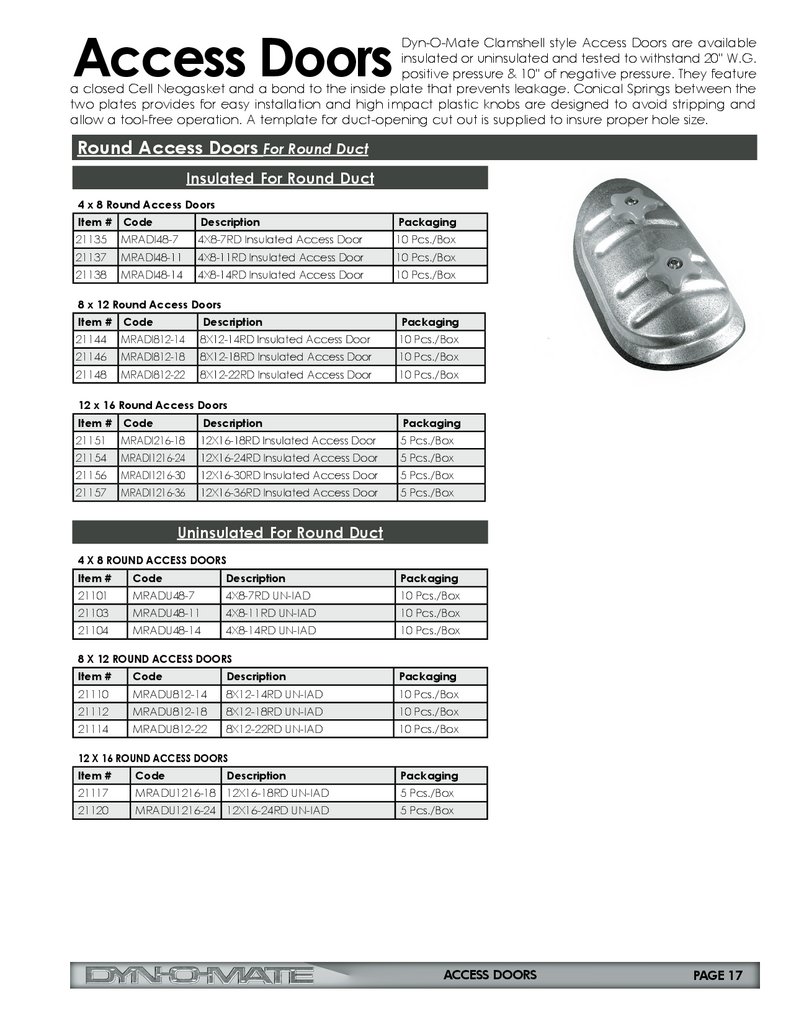
Access DoorsDyn-O-Mate Clamshell style Access Doors are available
insulated or uninsulated and tested to withstand 20'' W.G.
positive pressure & 10'' of negative pressure. They feature
a closed Cell Neogasket and a bond to the inside plate that prevents leakage. Conical Springs between the
two plates provides for easy installation and high impact plastic knobs are designed to avoid stripping and
allow a tool-free operation. A template for duct-opening cut out is supplied to insure proper hole size.
Round Access Doors For Round Duct
Insulated For Round Duct
4 x 8 Round Access Doors
Item #
Code
Description
Packaging
21135
MRADI48-7
4X8-7RD Insulated Access Door
10 Pcs./Box
21137
MRADI48-11
4X8-11RD Insulated Access Door
10 Pcs./Box
21138
MRADI48-14
4X8-14RD Insulated Access Door
10 Pcs./Box
8 x 12 Round Access Doors
Item #
Code
Description
Packaging
21144
MRADI812-14
8X12-14RD Insulated Access Door
10 Pcs./Box
21146
MRADI812-18
8X12-18RD Insulated Access Door
10 Pcs./Box
21148
MRADI812-22
8X12-22RD Insulated Access Door
10 Pcs./Box
12 x 16 Round Access Doors
Item #
Code
Description
Packaging
21151
MRADI216-18
12X16-18RD Insulated Access Door
5 Pcs./Box
21154
MRADI1216-24
12X16-24RD Insulated Access Door
5 Pcs./Box
21156
MRADI1216-30
12X16-30RD Insulated Access Door
5 Pcs./Box
21157
MRADI1216-36
12X16-36RD Insulated Access Door
5 Pcs./Box
Uninsulated For Round Duct
4 X 8 ROUND ACCESS DOORS
Item #
Code
Description
Packaging
21101
MRADU48-7
4X8-7RD UN-IAD
10 Pcs./Box
21103
MRADU48-11
4X8-11RD UN-IAD
10 Pcs./Box
21104
MRADU48-14
4X8-14RD UN-IAD
10 Pcs./Box
8 X 12 ROUND ACCESS DOORS
Item #
Code
Description
Packaging
21110
MRADU812-14
8X12-14RD UN-IAD
10 Pcs./Box
21112
MRADU812-18
8X12-18RD UN-IAD
10 Pcs./Box
21114
MRADU812-22
8X12-22RD UN-IAD
10 Pcs./Box
12 X 16 ROUND ACCESS DOORS
Item #
Code
Description
Packaging
21117
MRADU1216-18 12X16-18RD UN-IAD
5 Pcs./Box
21120
MRADU1216-24 12X16-24RD UN-IAD
5 Pcs./Box
ACCESS DOORS
PAGE 17
18.
Access Doors (continued)Flat Access Doors For Rectangular Duct
Insulated For Rectangular Duct
Item #
Code
Description
Packaging
21177
MFADI48
4X8 FLAT Insulated Access Door
10 Pcs./Box
21178
MFADI812
8X12 FLAT Insulated Access Door
10 Pcs./Box
21179
MFADI1216
12X16 FLAT Insulated Access Door
5 Pcs./Box
*High Temperature & other sizes available upon request.
Uninsulated For Rectangular Duct
Item #
Code
Description
Packaging
21170
MFADU48
4X8 FLAT UN-IAD
10 Pcs./Box
21171
MFADU812
8X12 FLAT UN-IAD
10 Pcs./Box
21172
MFADU1216
12X16 FLAT UN-IAD
5 Pcs./Box
High Temp. Access Doors
Access doors are used in duct systems for many reasons. Entry is often required to facilitate
duct cleaning, examine equipment, or to test, repair, and troubleshoot system components.
Duro Dyne high temperature access doors are designed for use in duct systems with temperatures of up to
2000˚F. The door is comprised of two steel plates attached to each other with spring loaded threaded studs.
High temperature access doors are shipped with a self-stick template to simplify installation. Once the hole is
cut, the two wing nuts on the door are loosened and the door is inserted into the duct at an angle so that the
duct wall can be situated between the access door’s lower and upper plates. The two wing nuts are then
tightened; sealing the duct opening between the two door plates.
Flat Uninsulated High Temp Access Doors
• Single Unit with No Pieces to Assemble
• All Steel Construction with Grease Tight Seal
• Stick-On Template for Cutting Hole
• Easy Slide-In and Fasten with Wing Nuts
PAGE 18
• High-Temperature 2000ºF Ceramic Gasket and Washer
• Optional FSB Cover Plate with Easy Remove Handle
• Complies with N.F.P.A. 96-Edition Section-4 Guidelines
• Complies with UL Construction Requirements
• Made in the U.S.A.
Item #
Code
Description
Packaging
21190
MHTAD2000804
2000 Degree Door Only 8x4
10 Pcs./Box
21191
MHTAD201208
2000 Degree Door Only 12x8
10 Pcs./Box
21192
MHTAD201612
2000 Degree Door Only 16x12
5 Pcs./Box
21195
MHTADC200804
2000 Degree Door w/Plate 8x4
10 Pcs./Box
21196
MHTADC201208
2000 Degree Door w/Plate 12x8
10 Pcs./Box
21197
MHTADC201612
2000 Degree Door w/Plate 16x12
5 Pcs./Box
HIGH TEMP ACCESS DOORS
19.
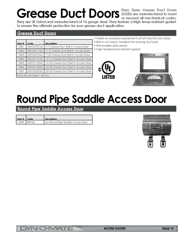
Grease Duct DoorsDuro Dyne Grease Duct Doors
(GDD) are manufactured to meet
or exceed all mechanical codes.
They are UL Listed and manufactured of 16 gauge steel. They feature a high temp resistant gasket
to ensure the ultimate protection for your grease duct application.
Grease Duct Doors
Item #
Code
Description
13001
DDGD0707UL
7X7 Grease Duct Bolt In Access Door
13002
DDGD0712UL
7X12 Grease Duct Bolt In Access Door
13003
DDGD0720UL
7X20 Grease Duct Bolt In Access Door
13004
DDGD1212UL
12X12 Grease Duct Bolt In Access Door
13005
DDGD1220UL
12X20 Grease Duct Bolt In Access Door
13006
DDGD1620UL
16X20 Grease Duct Bolt In Access Door
13007
DDGD2020UL
20X20 Grease Duct Bolt In Access Door
• Meets or exceeds requirements of all mechanical codes
• Bolt in unit easily installed into existing ductwork
• Removable door panel
• High temperature resistant gasket
Doors are packaged 1 per box.
Round Pipe Saddle Access Door
Round Pipe Saddle Access Door
Item #
Code
Description
13009
RPAD6
6in Round Pipe Saddle Access Door
ACCESS DOORS
PAGE 19
20.
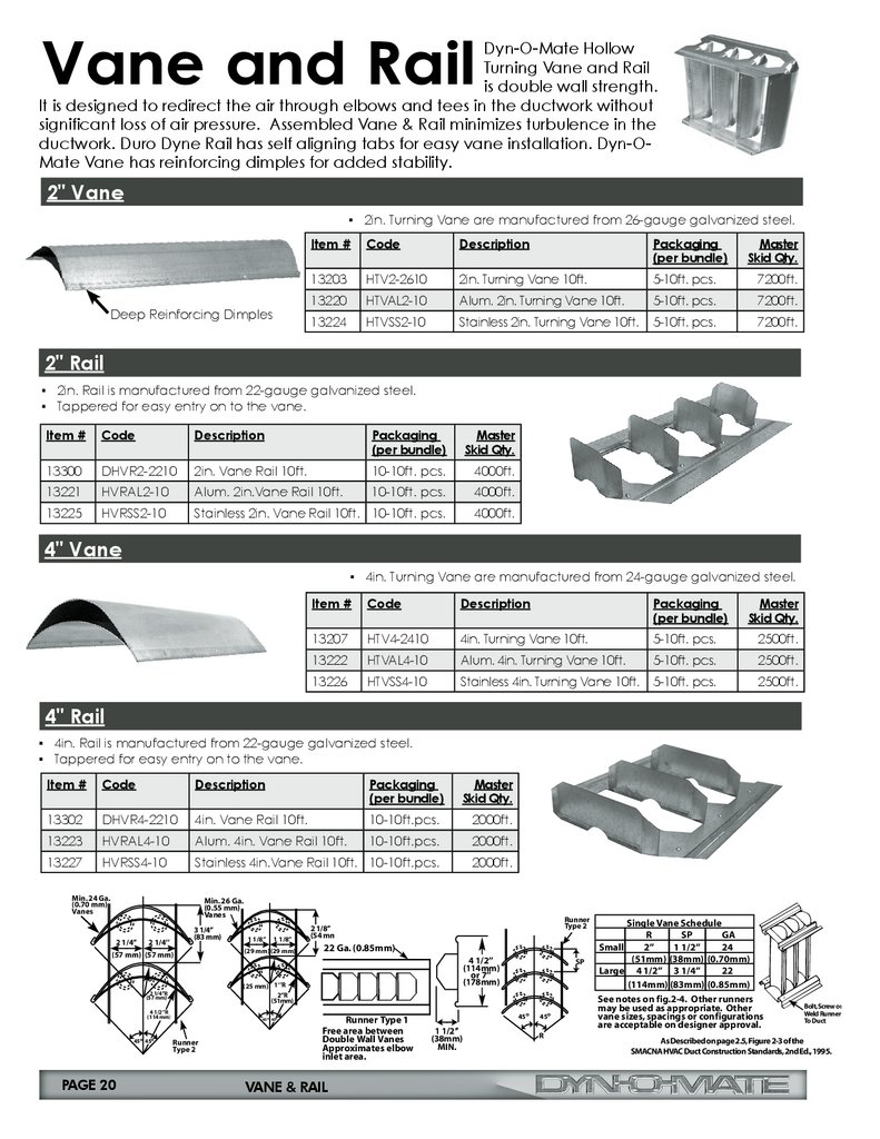
Vane and RailDyn-O-Mate Hollow
Turning Vane and Rail
is double wall strength.
It is designed to redirect the air through elbows and tees in the ductwork without
significant loss of air pressure. Assembled Vane & Rail minimizes turbulence in the
ductwork. Duro Dyne Rail has self aligning tabs for easy vane installation. Dyn-OMate Vane has reinforcing dimples for added stability.
2" Vane
▪ 2in. Turning Vane are manufactured from 26-gauge galvanized steel.
Deep Reinforcing Dimples
Item #
Code
Description
Packaging
(per bundle)
Master
Skid Qty.
13203
HTV2-2610
2in. Turning Vane 10ft.
5-10ft. pcs.
7200ft.
13220
HTVAL2-10
Alum. 2in. Turning Vane 10ft.
5-10ft. pcs.
7200ft.
13224
HTVSS2-10
Stainless 2in. Turning Vane 10ft.
5-10ft. pcs.
7200ft.
2" Rail
▪ 2in. Rail is manufactured from 22-gauge galvanized steel.
▪ Tappered for easy entry on to the vane.
Item #
Code
Description
Packaging
(per bundle)
Master
Skid Qty.
13300
DHVR2-2210
2in. Vane Rail 10ft.
10-10ft. pcs.
4000ft.
13221
HVRAL2-10
Alum. 2in.Vane Rail 10ft.
10-10ft. pcs.
4000ft.
13225
HVRSS2-10
Stainless 2in. Vane Rail 10ft. 10-10ft. pcs.
4000ft.
4" Vane
▪ 4in. Turning Vane are manufactured from 24-gauge galvanized steel.
Item #
Code
Description
(0.55 mm)
13207
HTV4-2410
4in. Turning Vane 10ft.
13222
HTVAL4-10
Alum. 4in. Turning Vane 10ft.
13226
HTVSS4-10
Stainless 4in. Turning Vane 10ft.
5-10ft. pcs. Vanes 2500ft.
3 1/4’’
(83 mm)
5-10ft.
2 1/4’’ pcs.
2 1/4’’
(57 mm) (57 mm)
4" Rail
5-10ft. pcs.
Code
Min. 24 Ga.
(0.70 mm)
Vanes
Description
45o 45o
Packaging
Master
(per bundle)3 1/4’’ Skid Qty.
13302
DHVR4-2210
4in. Vane Rail 10ft.
13223
HVRAL4-10
Alum. 4in. Vane Rail 10ft.
13227
HVRSS4-10
Stainless 4in.Vane Rail 10ft. 10-10ft.pcs.
2 1/4’’R
2 1/4’’
10-10ft.pcs.
2 1/4’’
(83 mm)
(57 mm) (57 mm)
10-10ft.pcs.
(57 mm)
1 1/8’’
Min. 26 Ga.
(0.55 mm)
Vanes
2 1/4’’
3 1/4’’
(83 mm)
2 1/4’’
(57 mm) (57 mm)
4 1/2’’R
(114 mm)
22 Ga. (0.85mm)
PAGE 20
1 1/8’’
1 1/8’’
(29 mm) (29 mm)
45o 45o
Runner
Type 2
2 1/8’’
(54 mm)
(25 mm) 1‘’R
2000ft.
2‘’R
45o 45o
Runner
Type 2
Runner
Type 2
4 1/2’’
(114mm)
or 7’’
(178mm)
SP
45o
1 1/2’’
(38mm)
MIN.
Single Vane Schedule
R
SP
GA
2’’
1 1/2’’
24
(51mm) (38mm) (0.70mm)
Large 4 1/2’’ 3 1/4’’
22
4 1/2’’VANE & RAILSP
(114mm)
or 7’’
Small
(178mm)
Runner
Type 2
45o
R
Runner
Type 2
22 Ga. (0.85mm)
4 1/2’’
(114mm)
or 7’’
(178mm)
Runner Type 1
Free area between
Double Wall Vanes
Approximates elbow
inlet area.
22 Ga. (0.85mm)
Runner Type 1
Free area between
Double Wall Vanes
Runner
Approximates
elbow
Type
2
inlet area.
45o 45o
2000ft.
(51mm)
(25 mm) 1‘’R
2‘’R
(51mm)
2 1/4’’R
(57 mm)
45o 45o
45o 45o
2 1/8’’
(54 mm)
1 1/8’’
2000ft.
(29 mm) (29 mm)
4 1/2’’R
(114 mm)
Min. 24 Ga.
(0.70 mm)
Vanes
(29 mm) (29 mm)
2500ft.
4 1/2’’R
(114 mm)
Min. 26 Ga.
(0.55 mm)
Vanes
2 1/8’’
(54 mm)
1 1/8’’ 1 1/8’’
2500ft.
(25 mm) 1‘’R
2‘’R
(51mm)
2 1/4’’R
(57 mm)
▪ 4in. Rail is manufactured from 22-gauge galvanized steel.
▪ Tappered for easy entry on to the vane.
Item #
Packaging
Master
(per bundle)Min. 26Skid
Ga. Qty.
Min. 24 Ga.
(0.70 mm)
Vanes
SP
45o
1 1/2’’
(38mm)
MIN.
Single Vane Schedule
R
SP
GA
Small
2’’
1 1/2’’
24
(51mm) (38mm) (0.70mm)
Large 4 1/2’’ 3 1/4’’
22
(114mm) (83mm) (0.85mm)
See notes on fig.2-4. Other runners
may be used as appropriate. Other
vane sizes, spacings or configurations
are acceptable on designer approval.
45o
R
Bolt, Screw or
Weld Runner
To Duct
As Described on page 2.5, Figure 2-3 of the
SMACNA HVAC Duct Construction Standards, 2nd Ed., 1995.
21.
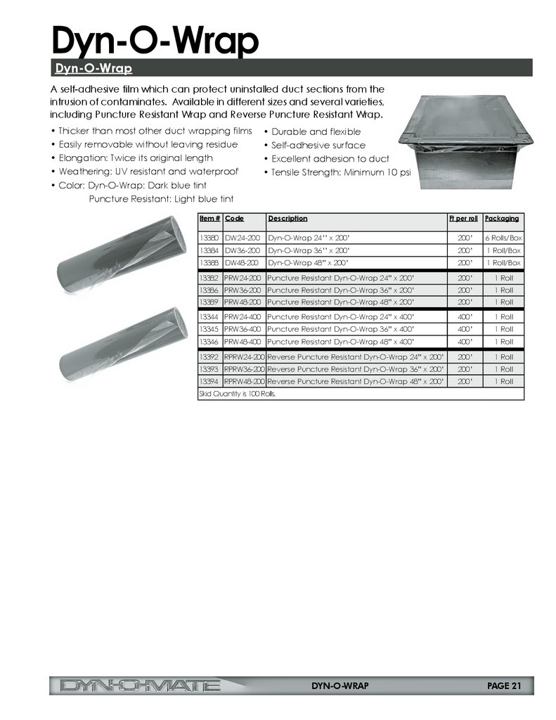
Dyn-O-WrapDyn-O-Wrap
A self-adhesive film which can protect uninstalled duct sections from the
intrusion of contaminates. Available in different sizes and several varieties,
including Puncture Resistant Wrap and Reverse Puncture Resistant Wrap.
• Thicker than most other duct wrapping films
• Easily removable without leaving residue
• Elongation: Twice its original length
• Weathering: UV resistant and waterproof
• Color: Dyn-O-Wrap: Dark blue tint
Puncture Resistant: Light blue tint
• Durable and flexible
• Self-adhesive surface
• Excellent adhesion to duct
• Tensile Strength: Minimum 10 psi
Item # Code
Description
Ft per roll Packaging
13380 DW24-200
Dyn-O-Wrap 24’’ x 200’
200’
6 Rolls/Box
13384 DW36-200
Dyn-O-Wrap 36’’ x 200’
200’
1 Roll/Box
13388 DW48-200
Dyn-O-Wrap 48” x 200’
200’
1 Roll/Box
13382 PRW24-200 Puncture Resistant Dyn-O-Wrap 24” x 200’
200’
1 Roll
13386 PRW36-200 Puncture Resistant Dyn-O-Wrap 36” x 200’
200’
1 Roll
13389 PRW48-200 Puncture Resistant Dyn-O-Wrap 48” x 200’
200’
1 Roll
13344 PRW24-400 Puncture Resistant Dyn-O-Wrap 24” x 400’
400’
1 Roll
13345 PRW36-400 Puncture Resistant Dyn-O-Wrap 36” x 400’
400’
1 Roll
13346 PRW48-400 Puncture Resistant Dyn-O-Wrap 48” x 400’
400’
1 Roll
13392 RPRW24-200 Reverse Puncture Resistant Dyn-O-Wrap 24” x 200’
200’
1 Roll
13393 RPRW36-200 Reverse Puncture Resistant Dyn-O-Wrap 36” x 200’
200’
1 Roll
13394 RPRW48-200 Reverse Puncture Resistant Dyn-O-Wrap 48” x 200’
200’
1 Roll
Skid Quantity is 100 Rolls.
DYN-O-WRAP
PAGE 21
22.
Air ToolThe Duro Air Gun is a versatile product used to reduce the effort put into labor
intensive tin-hammer work such as closing Pittsburgh locks, “Locking” vane to
rail, and inserting rod locks into conduit.
Duro Air Gun (DAG)
The Duro Air Gun (DAG) is sold without a tip and utilizes 90 PSI. Please see
below for all four Innovative, patent pending* tips that are available and
the capabilities they provide.
Item #
Code
Description
Packaging
13113
DAG
Duro Air Gun
1 each
Scan to see
demo of
Air Tools
Gun sold
separately
from tips.
Air Gun Accessory Tips
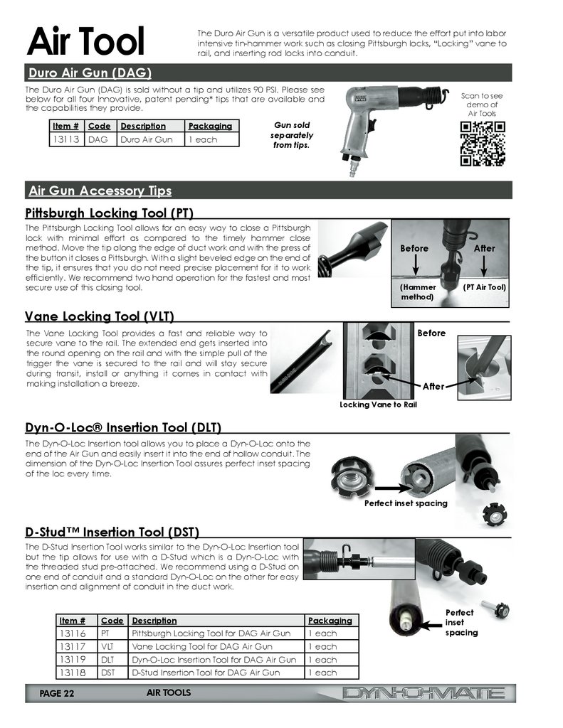
Pittsburgh Locking Tool (PT)
The Pittsburgh Locking Tool allows for an easy way to close a Pittsburgh
lock with minimal effort as compared to the timely hammer close
method. Move the tip along the edge of duct work and with the press of
the button it closes a Pittsburgh. With a slight beveled edge on the end of
the tip, it ensures that you do not need precise placement for it to work
efficiently. We recommend two hand operation for the fastest and most
secure use of this closing tool.
Before
After
(Hammer
method)
(PT Air Tool)
Vane Locking Tool (VLT)
Before
The Vane Locking Tool provides a fast and reliable way to
secure vane to the rail. The extended end gets inserted into
the round opening on the rail and with the simple pull of the
trigger the vane is secured to the rail and will stay secure
during transit, install or anything it comes in contact with
making installation a breeze.
After
Locking Vane to Rail
Dyn-O-Loc® Insertion Tool (DLT)
The Dyn-O-Loc Insertion tool allows you to place a Dyn-O-Loc onto the
end of the Air Gun and easily insert it into the end of hollow conduit. The
dimension of the Dyn-O-Loc Insertion Tool assures perfect inset spacing
of the loc every time.
Perfect inset spacing
D-Stud™ Insertion Tool (DST)
The D-Stud Insertion Tool works similar to the Dyn-O-Loc Insertion tool
but the tip allows for use with a D-Stud which is a Dyn-O-Loc with
the threaded stud pre-attached. We recommend using a D-Stud on
one end of conduit and a standard Dyn-O-Loc on the other for easy
insertion and alignment of conduit in the duct work.
Item #
Code Description
13116
13117
13119
13118
PT
Pittsburgh Locking Tool for DAG Air Gun
1 each
VLT
Vane Locking Tool for DAG Air Gun
1 each
DLT
Dyn-O-Loc Insertion Tool for DAG Air Gun
1 each
DST
D-Stud Insertion Tool for DAG Air Gun
1 each
PAGE 22
AIR TOOLS
Packaging
Perfect
inset
spacing
23.
Air HammerSuper Dyna-Hammer (for Pittsburgh Lock)
The Super Dyna-Hammer puts an
end to manual hammering with
the toughest tool in the industry.
Radius fittings and straight line duct
get powerfully knocked down at
approximately 20 feet per minute on
14 to 30 gauge metal. Manufactured
of 100% high grade tool steel for
durability and trouble-free years of
use. Fully rebuildable.
Straight & angled
ends included
Item #
Code
Description
Packaging
13263
SPDH
Super Dyna-Hammer for Pittsburgh Lock
1 each
Dyna-Hammer (for Pittsburgh Lock)
The Dyna-Hammer puts an end to manual hammering. Just
a couple of taps at the center and ends of standard length
duct to secure, then the Dyna-Hammer does all of the work.
Radius fittings and straight line duct get powerfully knocked
down at approximately 20 feet per minute on 14
to 30 gauge metal. Features an ergonomic, multistage trigger throttle, for better control during use.
Included multi-directional air hose swivel prevents
hose restriction during operation.
Item #
Code
Description
Packaging
13063
PDH
Dyna-Hammer for Pittsburgh Lock
1 each
Tools
9" Magnetic Drift Pin Ratchet Tool & Magnetic Wrench Insert 9/16in.
Patent No.
6,901,823
The 9” Magnetic Drift Pin Ratchet Tool is ideal for duct installation. The 9’’ long drift pin end
allows you to align two corners in a flange connection with ease.
Features:
• Heavy duty magnet to secure it to duct while not in use
• Cast steel
• Reversible for easy tightening & loosening
• For use on 3/8" nuts & bolts
• Magnetic Wrench Insert holds the wrench in a fixed position to
the nut or bolt to prevent slippage.
Magnet holds nut in place
so it doesn’t drop out
Item #
13289
13107
Code
MDPR916
MWI916
Description
Packaging
9in Magnetic Drift Pin Ratchet Tool 1 each
Magnetic Wrench Insert 9/16in
1 each
TOOLS
PAGE 23
24.
Tools (continued)TDC/TDF Crimper Tool
The Dyn-O-Mate Crimper installs the TDC or TDF corner and crimps
the edge over to hold the corner in place.
Features:
• Cast from high strength steel alloy • Cushion grip handles
• Precision machined jaws
• High leverage crimper tool
Item #
Code
Description
Packaging
21072
DOMCRMP
TDC/TDF Crimper Tool
1 each
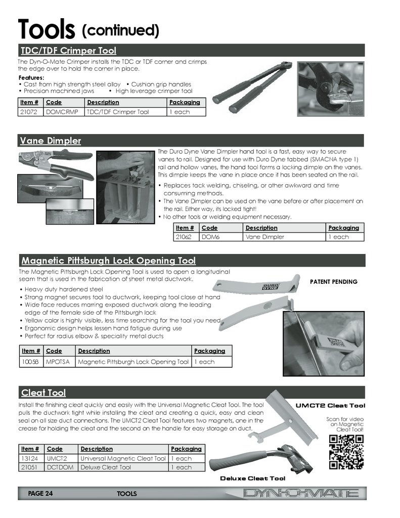
Vane Dimpler
The Duro Dyne Vane Dimpler hand tool is a fast, easy way to secure
vanes to rail. Designed for use with Duro Dyne tabbed (SMACNA type 1)
rail and hollow vanes, the hand tool forms a locking dimple on the vanes.
This dimple keeps the vane in place once it has been seated on the rail.
• Replaces tack welding, chiseling, or other awkward and time
consuming methods.
• The Vane Dimpler can be used on the vane before or after placement on
the rail. Either way, its locked tight!
• No other tools or welding equipment necessary.
Item #
Code
Description
Packaging
21062
DOM6
Vane Dimpler
1 each
Magnetic Pittsburgh Lock Opening Tool
The Magnetic Pittsburgh Lock Opening Tool is used to open a longitudinal
seam that is used in the fabrication of sheet metal ductwork.
PATENT PENDING
• Heavy duty hardened steel
• Strong magnet secures tool to ductwork, keeping tool close at hand
• Wide face reduces marring exposed ductwork along the leading
edge of the female side of the Pittsburgh lock
• Yellow color is highly visible, less time searching for the tool you need
• Ergonomic design helps lessen hand fatigue during use
• Perfect for radius elbow & speciality metal ducts
Item #
Code
Description
Packaging
10058
MPOTSA
Magnetic Pittsburgh Lock Opening Tool 1 each
Cleat Tool
Install the finishing cleat quickly and easily with the Universal Magnetic Cleat Tool. The tool
pulls the ductwork tight while installing the cleat and creating a quick, easy and clean
seal on all size duct connections. The UMCT2 Cleat Tool features two magnets, one in the
crease for holding the cleat and the second on the handle for easy storage on duct.
Item #
Code
Description
Packaging
13124
21051
UMCT2
DCTDOM
Universal Magnetic Cleat Tool 1 each
Deluxe Cleat Tool
1 each
Deluxe Cleat Tool
PAGE 24
TOOLS
UMCT2 Cleat Tool
Scan for video
on Magnetic
Cleat Tool!
25.
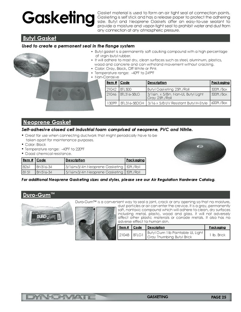
GasketingGasket material is used to form an air tight seal at connection points.
Gasketing is self stick and has a release paper to protect the adhering
side. Butyl and Neoprene Gaskets offer an easy-to-use sealant to
provide a moisture and vapor-tight seal to prohibit water and dust from
any connection at any atmospheric pressure.
Butyl Gasket
Used to create a permanent seal in the flange system
▪ Butyl gasket is a permanently soft caulking compound with a high percentage
of virgin butyl rubber.
▪ It will adhere to most dry, clean surfaces such as steel, aluminum, plastics,
wood and concrete and can withstand movement without cracking.
▪ Color: Gray, Black, Off White or Pink
▪ Temperature range: -40°F to 249°F
▪ Non-Corrosive
Item # Code
Description
Packaging
21042
21046
BTL500
BTL316-58LG
Butyl Gasketing 25ft./Roll
3/16in. x 5/8in. Non-UL Butyl Light
Gray 25ft./Roll
500ft./Box
500ft./Box
13099
BTL316-58DGH
3/16 x 5/8 UV Resistant Butyl H-Style
600ft./Box
Neoprene Gasket
Self-adhesive closed cell industrial foam comprised of neoprene, PVC and Nitrile.
▪ Great for use when connecting ductwork that might periodically have to be
taken apart for maintenance purposes.
▪ Color: Black
▪ Temperature range: -40°F to 220°F
▪ Good chemical resistance.
Item # Code
Description
Packaging
8261
BN316-34
3/16inx3/4in Neoprene Gasketing 50ft./Roll
8151
BN516-34
5/16inx3/4in Neoprene Gasketing 50ft./Roll
For additional Neoprene Gasketing sizes and styles, please see our Air Regulation Hardware Catalog.
Duro-Gum™
Duro-Gum™ is a convenient way to seal a joint, crack or any opening so that no moisture,
dust particles or air can enter the crevice. It is a gray, permanently
soft, nontoxic compound which will adhere to clean, dry surfaces
including metal, plastic, wood and glass. It will not adversely
affect other plastic materials or corrode metals. It also has no
adverse effect to human skin.
Item #
Code
Description
Packaging
21048
BTLG1
Butyl Gum 1lb Paintable UL Light
Gray Thumbing Butyl Brick
1 lb. Brick
GASKETING
PAGE 25
26.
ConduitConduit is used to support duct sizes over 48” or smaller duct in high pressure
applications. Duro Dyne offers conduit in 1/2” and 3/4” sizes in 10 ft. lengths.
Conduit
Item # Code
Description
Packaging
21099
21100
13051
1/2in Thin Wall Conduit - 10ft Lengths
3/4in Thin Wall Conduit - 10ft Lengths
1in Thin Wall Conduit - 10ft Lengths
10pcs. of 10 ft.
MC1210
MC3410
MC0110
10pcs. of 10 ft.
10pcs. of 10 ft.
Dyn-O-Loc & D-Stud
™
®
Dyn-O-Loc & D-Stud
Tie rods can be used to support duct sizes over 48". Dyn-O-Locs insert into the ends of the hollow tie rods to provide a
means of attaching the rods to the duct. Available for use in 1/2in. and 3/4in. I.D. rods. They are easily inserted and have
been pull tested to withstand over 1900 lbs.
Dyn-O-Loc
• Large self-sealing washer
• We put the washer on the bolt, so you don’t have to!
• Long bolt for easier installation
• Allows use of lighter gauge
Spring nut
Pre-assembled bolt
with washer
Locks conveniently packed
in separate poly bag.
Item #
Code
Description
Packaging
21097
DOMRL12-250
1/2in. Dyn-O-Loc (Full Set)
250/Box
21098
DOMRL34-250
3/4in. Dyn-O-Loc (Full Set)
250/Box
21208
DOMRL12-100
1/2in. Dyn-O-Loc Assembly (Full Set)
100/Box
21209
DOMRL34-100
3/4in. Dyn-O-Loc Assembly (Full Set)
100/Box
21008
SN12
1/2in. Dyn-O-Loc Spring Nut Only
250/Box
21009
21286
SN34
SWW1420
3/4in. Dyn-O-Loc Spring Nut Only
1/4-20 Dyn-O-Loc Bolt Only with Washer
250/Box
250/Box
D-Stud
The D-Stud is a Dyn-O-Loc with
the threaded stud pre-attached.
• Properly installed D-Studs are pull tested to over 1300 lbs.
• Anchors conduit in place during installation
• Works with both insulated and non-insulated duct work
• Allows for the installer to easily locate the pre-drilled hole
Item #
13021
13023
13025
13027
13029
13031
Code
DS12K-250
DS34K-250
DS12-250
DS34-250
DSGW-250
DSFN-250
Description
1/2in Dyn-O-Loc D-Stud Kit
3/4in Dyn-O-Loc D-Stud Kit
1/2in Dyn-O-Loc D-Stud Only
3/4in Dyn-O-Loc D-Stud Only
Dyn-O-Loc D-Stud Gasket Washer
Dyn-O-Loc D-Stud Flange Nut
Packaging
250/Box
250/Box
250/Box
250/Box
250/Box
250/Box
Dyn-O-Loc & D-Stud Insertion Tools
Manually insert Dyn-O-Locs and D-Studs quickly & easily at the correct
spacing depth with the Dyn-O-Loc & D-Stud Insertion Tools.
PAGE 26
DYN-O-LOC & D-STUD
Item #
Code
Description
Packaging
13120
MRLT
Magnetic Dyn-O-Loc Insertion Tool
1 each
13112
MDST
Magnetic D-Stud Insertion Tool
1 each
27.
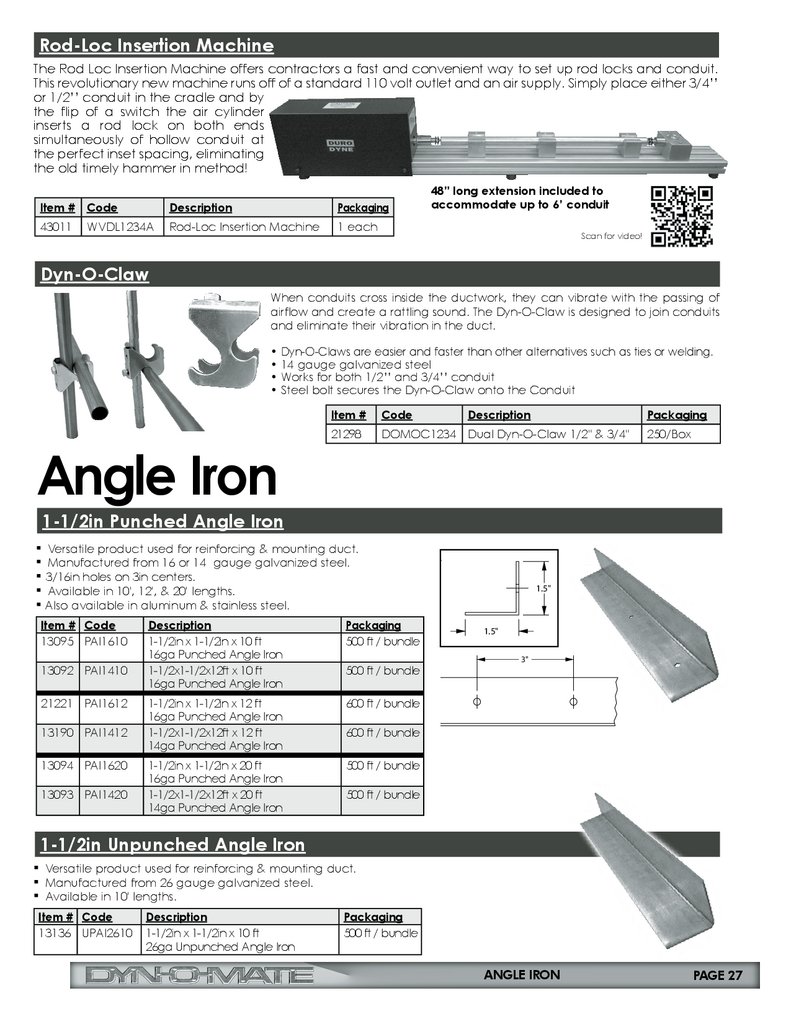
Rod-Loc Insertion MachineThe Rod Loc Insertion Machine offers contractors a fast and convenient way to set up rod locks and conduit.
This revolutionary new machine runs off of a standard 110 volt outlet and an air supply. Simply place either 3/4’’
or 1/2’’ conduit in the cradle and by
the flip of a switch the air cylinder
inserts a rod lock on both ends
simultaneously of hollow conduit at
the perfect inset spacing, eliminating
the old timely hammer in method!
Item # Code
Description
Packaging
43011
Rod-Loc Insertion Machine
1 each
WVDL1234A
48” long extension included to
accommodate up to 6’ conduit
Scan for video!
Dyn-O-Claw
When conduits cross inside the ductwork, they can vibrate with the passing of
airflow and create a rattling sound. The Dyn-O-Claw is designed to join conduits
and eliminate their vibration in the duct.
• Dyn-O-Claws are easier and faster than other alternatives such as ties or welding.
• 14 gauge galvanized steel
• Works for both 1/2’’ and 3/4’’ conduit
• Steel bolt secures the Dyn-O-Claw onto the Conduit
Angle Iron
Item #
Code
Description
Packaging
21298
DOMOC1234 Dual Dyn-O-Claw 1/2" & 3/4"
250/Box
1-1/2in Punched Angle Iron
3"
▪ Versatile product used for reinforcing & mounting duct.
▪ Manufactured from 16 or 14 gauge galvanized steel.
▪ 3/16in holes on 3in centers.
▪ Available in 10', 12', & 20' lengths.
▪ Also available in aluminum & stainless steel.
Item # Code
13095 PAI1610
13092 PAI1410
21221 PAI1612
13190 PAI1412
13094 PAI1620
13093 PAI1420
Description
1-1/2in x 1-1/2in x 10 ft
16ga Punched Angle Iron
1-1/2x1-1/2x12ft x 10 ft
16ga Punched Angle Iron
Packaging
500 ft / bundle
1-1/2in x 1-1/2in x 12 ft
16ga Punched Angle Iron
1-1/2x1-1/2x12ft x 12 ft
14ga Punched Angle Iron
600 ft / bundle
1-1/2in x 1-1/2in x 20 ft
16ga Punched Angle Iron
1-1/2x1-1/2x12ft x 20 ft
14ga Punched Angle Iron
500 ft / bundle
500 ft / bundle
1.5"
1.5"
3"
1.5"
600 ft / bundle
1.5"
500 ft / bundle
1-1/2in Unpunched Angle Iron
▪ Versatile product used for reinforcing & mounting duct.
▪ Manufactured from 26 gauge galvanized steel.
▪ Available in 10' lengths.
Item # Code
13136 UPAI2610
Description
1-1/2in x 1-1/2in x 10 ft
26ga Unpunched Angle Iron
Packaging
500 ft / bundle
ANGLE IRON
PAGE 27
28.
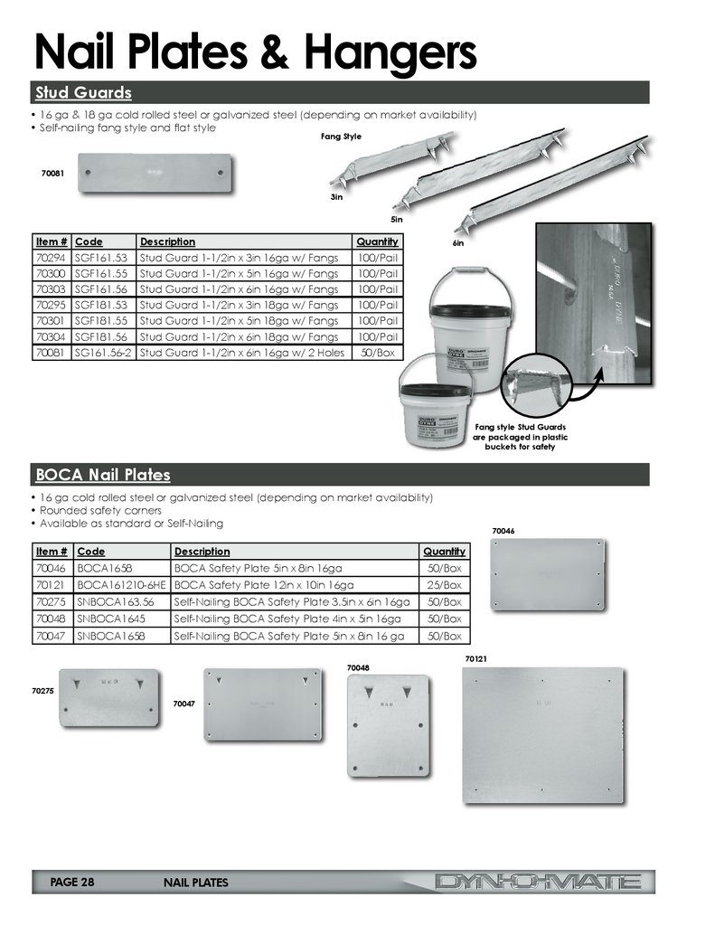
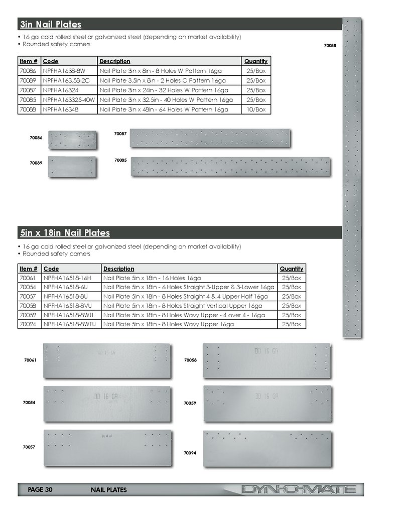
Nail Plates & HangersStud Guards
• 16 ga & 18 ga cold rolled steel or galvanized steel (depending on market availability)
• Self-nailing fang style and flat style
Fang Style
70081
3in
5in
Item # Code
70294 SGF161.53
Description
Stud Guard 1-1/2in x 3in 16ga w/ Fangs
Quantity
100/Pail
70300 SGF161.55
Stud Guard 1-1/2in x 5in 16ga w/ Fangs
100/Pail
70303 SGF161.56
Stud Guard 1-1/2in x 6in 16ga w/ Fangs
100/Pail
70295 SGF181.53
Stud Guard 1-1/2in x 3in 18ga w/ Fangs
100/Pail
70301 SGF181.55
Stud Guard 1-1/2in x 5in 18ga w/ Fangs
100/Pail
70304 SGF181.56
Stud Guard 1-1/2in x 6in 18ga w/ Fangs
100/Pail
70081 SG161.56-2 Stud Guard 1-1/2in x 6in 16ga w/ 2 Holes
50/Box
6in
Fang style Stud Guards
are packaged in plastic
buckets for safety
BOCA Nail Plates
• 16 ga cold rolled steel or galvanized steel (depending on market availability)
• Rounded safety corners
• Available as standard or Self-Nailing
70046
Item # Code
Description
Quantity
70046
BOCA1658
BOCA Safety Plate 5in x 8in 16ga
50/Box
70121
BOCA161210-6HE BOCA Safety Plate 12in x 10in 16ga
25/Box
70275
SNBOCA163.56
Self-Nailing BOCA Safety Plate 3.5in x 6in 16ga
50/Box
70048
SNBOCA1645
Self-Nailing BOCA Safety Plate 4in x 5in 16ga
50/Box
70047
SNBOCA1658
Self-Nailing BOCA Safety Plate 5in x 8in 16 ga
50/Box
70048
70275
70047
PAGE 28
NAIL PLATES
70121
29.
1.5in Nail Plates• 16 or 18 ga cold rolled steel or galvanized steel (depending on market availability)
• Rounded safety corners
Item #
Code
Description
Quantity
70082
NPFHA161.59-4W
Nail Plate 1-1/2in x 9in - 4 Hole W Pattern 16ga
50/Box
70076
NPFHA161.512-4W
Nail Plate 1-1/2in x 12in - 4 Hole W Pattern 16ga
50/Box
70077
NPFHA161.512-8W
Nail Plate 1-1/2in x 12in - 8 Hole W Pattern 16ga
50/Box
70078
NPFHA161.518-8W
Nail Plate 1-1/2in x 18in - 8 Hole W Pattern 16ga
50/Box
70079
NPFHA161.5124-8W
Nail Plate 1-1/2in x 24in - 8 Hole W Pattern 16ga
50/Box
70080
NPFHA161.524-32Z
Nail Plate 1-1/2in x 24in - 32 Hole Z Pattern 16ga
50/Box
70093
NPFHA181.518-3AM Nail Plate 1-1/2in x 18in - 3 Angled Holes & 1 Center Hole 18ga
70082
70078
70076
70079
70077
70080
50/Box
70093
3in x 18in Nail Plates
• 16 ga or 18 ga cold rolled steel or galvanized steel (depending on market availability)
• Rounded safety corners
Item # Code
Description
Quantity
70065
NPFHA16318-4
Nail Plate 3in x 18in - 4 Holes 16ga
25/Box
70064
NPFHA16318-8
Nail Plate 3in x 18in - 8 Holes 16ga
25/Box
70063
NPFHA16318-8W
Nail Plate 3in x 18in - 8 Holes Wavy Pattern 16ga
25/Box
70084
NPFHA16318-9H
Nail Plate 3in x 18in - 9 Holes H Pattern 16ga
25/Box
70083
NPFHA16318-16H
Nail Plate 3in x 18in - 16 Holes H Pattern 16ga
25/Box
70092
NPFHA18318-4
Nail Plate 3in x 18in - 4 Holes 18ga
25/Box
70091
NPFHA18318-8
Nail Plate 3in x 18in - 8 Holes 18ga
25/Box
70065
70083
70064
70092
70063
70091
70084
NAIL PLATES
PAGE 29
30.
3in Nail Plates• 16 ga cold rolled steel or galvanized steel (depending on market availability)
• Rounded safety corners
70088
Item # Code
Description
Quantity
70086
NPFHA1638-8W
Nail Plate 3in x 8in - 8 Holes W Pattern 16ga
25/Box
70089
NPFHA163.58-2C
Nail Plate 3.5in x 8in - 2 Holes C Pattern 16ga
25/Box
70087
NPFHA16324
Nail Plate 3in x 24in - 32 Holes W Pattern 16ga
25/Box
70085
NPFHA163325-40W Nail Plate 3in x 32.5in - 40 Holes W Pattern 16ga
25/Box
70088
NPFHA16348
10/Box
Nail Plate 3in x 48in - 64 Holes W Pattern 16ga
70087
70086
70085
70089
5in x 18in Nail Plates
• 16 ga cold rolled steel or galvanized steel (depending on market availability)
• Rounded safety corners
Item #
Code
Description
Quantity
70061
NPFHA16518-16H
Nail Plate 5in x 18in - 16 Holes 16ga
25/Box
70054
NPFHA16518-6U
Nail Plate 5in x 18in - 6 Holes Straight 3-Upper & 3-Lower 16ga
25/Box
70057
NPFHA16518-8U
Nail Plate 5in x 18in - 8 Holes Straight 4 & 4 Upper Half 16ga
25/Box
70058
NPFHA16518-8VU
Nail Plate 5in x 18in - 8 Holes Straight Vertical Upper 16ga
25/Box
70059
NPFHA16518-8WU
Nail Plate 5in x 18in - 8 Holes Wavy Upper - 4 over 4 - 16ga
25/Box
70094
NPFHA16518-8WTU
Nail Plate 5in x 18in - 8 Holes Wavy Upper 16ga
25/Box
70061
70058
70054
70059
70057
70094
PAGE 30
NAIL PLATES
31.
5in Nail Plates• 16 ga cold rolled steel or galvanized steel (depending on market availability)
• Rounded safety corners
Item #
Code
Description
Quantity
70090
NPFHA16516-3V
Nail Plate 5in x 16in - 3 Holes 16ga
25/Box
70095
NPFHA16524-8W Nail Plate 5in x 24in - 8 Holes W Pattern 16ga
70090
25/Box
70095
Z Brackets
• 18 ga galvanized steel
• 3/4in wide
• Rounded safety corners
• Central slot for initial duct adjustment before final attachment
Item #
70008
70009
70010
70011
70012
Code
ZB8
ZBL9
ZBXL10
ZBXXL11
ZBXXXL12
Description
8” Z Bracket
9” Z Bracket
10” Z Bracket
11” Z Bracket
12” Z Bracket
Quantity
100/Box
100/Box
100/Box
100/Box
100/Box
Pre-drilled slotted
hole for easy
adjustment during
installation
Easy Break Gas Pipe Hanger
• 16 ga galvanized steel
• Structural perforations for dual length or single length use
• Infinite adjustability for easy installation
Item # Code
Description
Quantity
70021
GPH1615-2 Gas Pipe Hanger 15in x 1in w/ 7/8in diameter double holes
250/Pail
70022
GPH167.5-1 Gas Pipe Hanger 7.5in x 1in w/ 7/8in diameter single hole
250/Box
Structural perforation for
multi configuration pipe
support applications
Multi-Duct 'L' Bracket
• 18 ga galvanized steel
• 1” scribe for proper placement on wrapped duct
• Rounded safety corners
Item #
Code
Description
Quantity
70027
MDB12
1/2in Wide Multi-Duct ‘L’ Bracket
100/Box
70028
MDB12Q
1/2in Wide Multi-Duct ‘L’ Bracket
250/Box
70029
MDB12F
1/2in Wide Multi-Duct ‘L’ Bracket
500/Box
70030
MDB12B
1/2in Wide Multi-Duct ‘L’ Bracket Bulk
1000/Box
NAIL PLATES
PAGE 31
32.
Assembly Instructionsfor Flange/J&H Systems
Step 1: Cutting the Angle
The angle should be cut 1 5/16'' shorter than the duct dimensions,
cutting the angle with the spine pointing up. Using a chop saw
with a 3 h.p. motor and a metal cutting blade helps to insure a
clean edge with no burrs.
Step 2: Frame Assembly & Seating
Using a mallet, insert the corners into the shorter angles; install
the larger angles to complete the frame. The raised portion of
the corner should be facing inward with the "Dyn-O-Mate" name
visible from the outside.
Starting at a corner, use a mallet, hammer the completed frame
onto the raw edge of the duct section. Moving in one direction,
make sure the duct is seated into the mastic.
NOTE: The duct section should not be notched.
Step 3: Fastening the Frame
The frame can be fastened to the ductwork with either Tek screws
(10x3/4) or spot welds.
Fastening of the angle or spot welding must start within 3/4'' of
each end of the angle at the duct section corners.
Step 4: Gasket Application
Apply a 2 to 3'' strip of gasket on the 4 exposed corners of one frame,
as pictured.
Starting at the center of the other mating frame, apply a single strap of
gasket completely around the inside edge of the frame. IMPORTANT:
This gasket must also cover the exposed edge of the duct section and
the gap between the duct wall and the corner.
Step 5: Installing the Cleat
Snap a 6'' piece of either metal or PVC cleat over the mating frame,
using the following recommendations:
• 1/2'' to 2''sp - 1 piece on 24''centers
• 2'' to 3'' sp - 1 piece on 18'' centers
• 4'' to 6'' sp - 1 piece on 12'' centers
• Over 10''sp - continuous cleat
PAGE 32
ASSEMBLY INSTRUCTIONS
33.
To Whom It May Concern:SUBJECT: Duct construction other than that in the HVAC-DCS-1985
The foreword of the 1985 HVAC-DCS states that "Although standardization intrinsically
involves selection, no intention of discrimination against the use of any product or
method that would serve a designers's need equally or better exists." Additionally,
recognition of equivalent or other construction is acknowledged in the text as follows:
1. Italicized wording in paragraph one on page 1-12 states "a fifth alternative,
that of using non-illustrated construction, is recognized based on sponsor dem onstrated equivalency subject to the approval of authorities regulating use of
this voluntary acceptance standard. SMACNA does not validate equivalency."
2. Text on page 1-14 states that "certain joints have been assigned maximum
pressure classes. Such restrictions are not intended to prohibit consideration
of other limits where evidence of acceptability is presented under the equiva lent construction principle."
3. Paragraph S 1.18 on page 1-15 states that "Other construction that meets the
functional criteria in Section VII or is as serviceable as that produced by the
construction tables may be provided."
4. A sentence on page 1-37 says "See Figure 1-4A for commentary on propri etary joint systems and see Section VII for joint performance evaluation."
5. The text on page 1-38 "invites authorities to consider alternative constructions"
and says "consult the manufacturers of alternative systems for ratings, assembly
requirements and recommendations."
6. Note 3 on page IV states that "the Association refrains from endorsement of
proprietary products." Note 4 on this page says "the Association will not review
or judge products or components as being in compliance with the document."
7. Paragraph S 3.3 on page 3-2 says "Nothing herein is intended to constitute
implied disapproval of the designer's consideration of other methods of construction."
8. Paragraph S 3.26 on page 3-13 states that "Illustrations of accessories and
sleeves and collars are representative of a class of such items and are not
intended to preclude the use of components not precisely identical to these."
9. Three alternative procedures for rating construction relative to the SMACNA
tables are given on page 7-5, analysis, historical track record and testing.
Commentary on witnessing tests and on use of test data is provided in the last
paragraph on page 7-11, ending with "Authorities are invited to evaluate such
construction based on evidence presented by sponsors." Otherwise, the per formance criteria used for the SMACNA rectangular duct tables are given in
Section VII. General performance requirements are discussed on page 1-3.
We think that these statements from the HVAC-DCS reflect a clear policy of SMACNA's
abstention from judging unillustrated components and systems as being equivalent
while encouraging consideration of them based on evidence presented by sponsors.
Otherwise, SMACNA has not published or authorized any addenda for the 1985 HVAC-DCS.
Sincerely,
John H. Stratton
Director, Technical Services
SMACNA POLICY
PAGE 33
34.
SHOP STANDARDS1/2” W.G.
Static
pos or neg
Duct
Dimen.
RECTANGULAR DUCT REINFORCEMENT
Minimum Rigidity Class* - Minimum Gage Duct
Reinforcement Spacing
R=Midpoint Reinforcement
T=Conduit Type Tie Rods
*=These tests were done as comparative tests, and the actual duct deflection was not recorded. They did not exceed
SMACNA Deflection Standards.
Note: Two (2) Tie Rods - equally spaced (28'' centerline) were used
8'
6'
5'
4'
3'
2 1/2'
2'
26'' dn
H-26
H-26
H-26
H-26
H-26
H-26
H-26
27-30''
H-26
H-26
H-26
H-26
H-26
H-26
H-26
31-36''
H-24
H-26
H-26
H-26
H-26
H-26
H-26
37-42''
H-24
H-24
H-26
H-26
H-26
H-26
H-26
43-48''
H-22
H-24
H-26
H-26
H-26
H-26
H-26
49-54''
H-20
H-22
H-26
H-26
H-26
H-26
H-26
55-60''
H-20
H-22
H-24
H-24
H-26
H-26
H-26
61-72''
H-18
H-20
H-22 J26T
H-24
H-24
H-24
H-24
73-84''
J-16
H-18
H-22 J26T
H-24
H-24
H-24
H-24
85-96''
J-16
H-22
H-22
H-22
H-22
J-18 J22T H-20
J22
97-108''
J22T J-18 J22T J-18 J22T H-18 J-22 H-18 J-22 H-18 J22
109-120''
J22T
J22T
J22T
J-18 J22T H-18 J-22 H-18 J22
When referring to Table 1-3 thru Table 1-10 in the SMACNA HVAC Duct Construction
Standards, 3rd ed., 2005,
Use the Dyn-O-Mate “H” Angle on Rigidity Class “F”, “G” and “H”
Use the Dyn-O-Mate “J” Angle on Rigidity Classes above “H”
The tables as shown here are the SMACNA Tables with those interpretations
already substituted.
These tests results are shown as follows:
SMACNA Table
PAGE 34
DUCT CONSTRUCTION STANDARDS
Variation
permitted per
certified test.
35.
SHOP STANDARDS1” W.G.
Static
pos or neg
Duct
Dimen.
RECTANGULAR DUCT REINFORCEMENT
Minimum Rigidity Class* - Minimum Gage Duct
Reinforcement Spacing
R=Midpoint Reinforcement
T=Conduit Type Tie Rods
*=These tests were done as comparative tests, and the actual duct deflection was not recorded. They did not exceed
SMACNA Deflection Standards.
Note: Two (2) Tie Rods - equally spaced (28'' centerline) were used
8'
6'
5'
4'
3'
2 1/2'
2'
14'' dn
H-26
H-26
H-26
H-26
H-26
H-26
H-26
15-20''
H-26
H-26
H-26
H-26
H-26
H-26
H-26
21-24''
H-24
H-26
H-26
H-26
H-26
H-26
H-26
25-30''
H-24
H-26
H-26
H-26
H-26
H-26
H-26
31-36''
H-22
H-24
H-24 H-26
H-26
H-26
H-26
H-26
37-42''
H-20
H-22
H-24 H-26
H-26
H-26
H-26
H-26
43-48''
H-18
H-20
H-22 H-26
H-26
H-26
H-26
H-26
49-54''
H-18
H-20
H-22 J-26 H-24 J-26
H-24 J-26 H-24 J-26 H-24 J-26
55-60''
H-18
H-20
H-22 J-26 H-24 J-26
H-24 J-26 H-24 J-26 H-24 J-26
24
26T
61-72'''
H-18
H-18 J
73-84''
J-16
J-18
J24T J-20
J22
H-22
J22
H-22 J-24 H-22 J-24
J-16
J-20 J-18
J-20
J-20
J22
H-20 J-22
97-108''
J22T J-18 J22T
J-18
J22T J-18
J-22 J-18 J-22
109-120''
J22T
J-18
J22T J-18
J-22 J-18 J-22
85-96''
H-22 J26T
J22T
H-24 J26T H-24 J-26 H-24 J-26
H-22
* Each duct system shall be constructed for the specific duct pressure classifications shown on the contract
drawings for the project. Where no specific duct pressure class designations are provided by the designer the
1” water gage pressure class is the basis of compliance with these standards, regardless of velocity in the duct,
except when the duct is variable volume: All variable volume duct upstream of VAV boxes has a 2” w.g. basis of
compliance when the designer does not give a pressure class.
*Because total pressure decreases in the direction of the flow a, duct construction pressure classification equal
to fan outlet pressure (or to fan total static pressure rating) cannot economically be imposed on the entire duct
system. Pressure in ducts near room air terminals is nearly always below 1/2” w.g.
*Asterisks indicate wording that is taken directly and verbatim from the SMACNA HVAC Duct Construction
Standards, 3rd ed., 2005.
SMACNA TABLE 1-2 DUCT SEALING REQUIREMENTS
Seal Class
Class
Sealing Required
Static Pressure
Construction Class
A
All transverse joints, longitudinal seams
and duct wall penetrations
4” w.g. and up
B
All transverse joints and longitudinal
seams
3” w.g.
C
Transverse Joint
2” w.g.
In addition to the above, any variable air volume system duct of 1” and 1/2” w.g. construction class that is up
stream of the VAV boxes shall meet Seal Class C.
DUCT CONSTRUCTION STANDARDS
PAGE 35
36.
SHOP STANDARDS2” W.G.
Static
pos or neg
Duct
Dimen.
RECTANGULAR DUCT REINFORCEMENT
Minimum Rigidity Class* - Minimum Gage Duct
Reinforcement Spacing
R=Midpoint Reinforcement
T=Conduit Type Tie Rods
*=These tests were done as comparative tests, and the actual duct deflection was not recorded. They did not exceed
SMACNA Deflection Standards.
Note: Two (2) Tie Rods - equally spaced (28'' centerline) were used
8'
6'
5'
4'
3'
2 1/2'
2'
12'' dn
H-26
H-26
H-26
H-26
H-26
H-26
H-26
13-18''
H-24
H-24
H-26
H-26
H-26
H-26
H-26
19-26''
H-22
H-24
H-26
H-26
H-26
H-26
H-26
27-30''
H-20
H-22
H-24
H-26
H-26
H-26
H-26
31-36''
H-18
H-20
H-22 H-24
H-24
H-26
H-26
H-26
37-42''
H-16
H-18
H-20 H-24
H-24
H-24
H-26
H-26
H-18
H-22 J26T
H-24
H-24
H-24
22
26T
22
26T
H-24
H-24
H-24
H-22
H-24
H-24
H-22
H-22 H-24
H-24
49-54''
J-16
H-18
55-60''
J-16
J-18
H22
J26T
22
J 26T
22
J 26T
J-16
J24T
J-18
J26T
73-84''
J22T
J-18
J22T
J-20
J-24
J-22
J-24 J-22 H-24
85-96''
J22T
J-18
J22T
J-18
J-20
J-20
J-22 J-22 J-22
97-108''
JT22T
JT22T K-18 JT22T J-18
J-22 J-18 J-22
109-120''
JT22T
JT22T
43-48''
J-16
61-72'''
H-20
H-20 J
H-18 J
JT22T K-18 J-22 J-18 J-22
Tie Rod Installation
Using the Dyn-O-Mate RODLOCK(Conduit Type Tie Rod) Duro Dyne Corp., through a certified testing Program
(in accordance with Chapter 7 of the SMACNA HVAC Duct Construction Standards, 3rd ed., 2005) has used
the Conduit Type Tie Rod being attached to the duct wall alone as the reinforcement for the panel tie rod.
Example: 22 T Center tie rod:
Where the Conduit Type Tie Rod is used as a flange reinforcement, “JT” or “HT”, the conduit type tie rod is
installed as shown below:
1/4-20 x 1’’ Hex
Grade 5 Bolt
1’’ OD NEO/
GALV. Washer
(No Sealant
required)
1’’
ROD LOCK
Drive in with
installation tool
Pull tested to 1,909 lbs.
Drill 5/16
dia hole
into duct
wall
1/2’’ Thinwall
Conduit
Negative Pressure
Consult SMACNA construction standards page 2.97 Section 2.8.1 paragraph 7 for specifics on
reinforcement recommendations for both Positive and negative pressure duct systems.
PAGE 36
DUCT CONSTRUCTION STANDARDS
37.
SHOP STANDARDS3” W.G.
Static
pos or neg
Duct
Dimen.
RECTANGULAR DUCT REINFORCEMENT
Minimum Rigidity Class* - Minimum Gage Duct
Reinforcement Spacing
R=Midpoint Reinforcement
T=Conduit Type Tie Rods
*=These tests were done as comparative tests, and the actual duct deflection was not recorded. They did not exceed
SMACNA Deflection Standards.
Note: Two (2) Tie Rods - equally spaced (28'' centerline) were used
8'
6'
5'
4'
3'
2 1/2'
2'
12'' dn
H-24
H-26
H-26
H-26
H-26
H-26
H-26
13-18''
H-22
H-24
H-24 H-26
H-26
H-26
H-26
H-26
19-22''
H-20
H-22
H-24 H-26 H-24
H-26
H-26
H-26
H-26
23,24''
H-18
H-22
H-24 H-26 H-24
H-26
H-26
H-26
H-26
25,26''
H-18
H-22
H-24
H-24
H-26
H-26
H-26
27,28''
H-18
H-20
H-22 H-24
H-24
H-26
H-26
H-26
29,30''
H-18
H-20
H-22 H-24
H-24
H-26
H-26
H-26
31-36''
H-16
H-18
H-20 H-24 H-22
H-24 H-24 H-24
H-26
H-26
37-42''
H-18
H-20 H-24 H-22
H-24 H-24 H-24 H-24 H-24
H-26
43-48''
J-16
J-18
J26T
H-20
J26T
H-22
H-24
H-24
49-54''
J-18
J26T
J-18
J26T
H-22
H-24
H-24
55-60''
J-16
J24T
J-18
J24T
H-20
H-22
H-24
61-72''
J24T
J-16
J24T
J-20
J24T
J-22
J-24
J-24
73-84''
J20T
J20T
J-18
J20T
J-20
J-22
J-22
85-96''
JT20T
JT20T K-18 JT20T J-18
J-20
J-20
97-108''
JT20T
JT20T
JT20T L-18 JT20 K-18 JT20
109-120''
JT20T
JT20T
JT20T L-18 JT20 L-18 JT20
This table shows some typical duct sizes and the weight that can be
saved by changing gage per certified test:
SMACNA Table
Duct Size
Sq. Ft. per
5'' Sect.
30/18
36/24
42/24
48/24
54/24
60/30
72/36
84/48
96/48
40
50
55
60
65
75
90
110
120
Variation permitted per certified test.
Lbs./Sq. Ft.
.91
26 ga.
40
50
55
60
65
75
90
110
120
Lbs./Sq. Ft.
1.16
24 ga.
51
64
70
76
83
96
115
140
153
Lbs./Sq. Ft.
1.41
22 ga.
62
76
85
93
101
116
140
171
186
Lbs./Sq. Ft. Lbs./Sq. Ft.
1.66
2.16
20 ga.
18 ga.
73
95
83
119
100
131
110
143
119
154
137
178
164
214
201
261
219
285
DUCT CONSTRUCTION STANDARDS
PAGE 37
38.
SHOP STANDARDS4” W.G.
Static
pos or neg
Duct
Dimen.
RECTANGULAR DUCT REINFORCEMENT
Minimum Rigidity Class* - Minimum Gage Duct
Reinforcement Spacing
R=Midpoint Reinforcement
T=Conduit Type Tie Rods
*=These tests were done as comparative tests, and the actual duct deflection was not recorded. They did not exceed
SMACNA Deflection Standards.
Note: Two (2) Tie Rods - equally spaced (28'' centerline) were used
8'
6'
5'
4'
3'
2 1/2'
2'
10'' dn
H-22
H-26
H-26
H-26
H-26
H-26
H-26
11,12''
H-22
H-24
H-26
H-26
H-26
H-26
H-26
13,14''
H-22
H-22
H-24
H-26
H-26
H-26
H-26
15,16''
H-20
H-22
H-24
H-26
H-26
H-26
H-26
17-20''
H-20
H-22
H-24
H-24
H-26
H-26
H-26
21,22''
H-18
H-20
H-24
H-24
H-26
H-26
H-26
23,26''
27-30''
H-18
H-18
H-20
H-18
H-22 H-24
H-24
H-22 H-24 H-24 H-24
H-26
H-26
H-26
H-26
H-26
H-26
31-36''
H-18
H-20 H-22
H-24
H-26
H-26
37-42''
J-16
J-18 H-22 H-20 H-22
H-22
H-24
H-26
43-48''
J-18 J26T
J-18
J26T
H-22
H-24
H-24
49-54''
J-16 J24T
J-18
J24T
J-20
H-22
H-24
55-60''
J-16 J22T
J-16
J22T
J-20
J-22
H-24
61-72''
J20T
J20T
J-18
J-20 J-20 J-24 J-22 H-24
73-84''
J20T
J20T
K-16
J20T
85-96''
JT20T
JT20T
JT20T K-18 JT20
97-108''
JT18T
JT18T
JT20T L-18 JT20 L-18 JT20
109-120''
JT18T
JT18T
JT18T L-18 JT18 L-18 JT18
H-22
J-18
J-20
J-20 J-22
J-20
Precautions
In any given duct system, accidental overpressure could occur and must be accounted for by design provisions, such as fail safe features, replaceable release panels and static pressure switches that can shut down
the entire system. Note: On all duct systems that are to be tested for leakage, it is recommended that the
first 100 feet of completed ductwork be tested before proceeding to complete the installation.
STEP ONE
SHIPPING L SHAPED DUCT WITH THE ANGLE INSTALLED
STEP TWO
STEP THREE
STEP FOUR
Complete the frame and
bend over the hammer
edge of the Pitts-burgh
Lock in the standard
manner.
Notch the “hammer
edge” of the female
Pittsburgh Lock 1/4” on
a 45 degree angle as
shown.
PAGE 38
In the shop, install the
angle on the duct without the corner piece.
DUCT CONSTRUCTION STANDARDS
In the field insert a corner
piece into the angle at the
male end of the Pittsburgh
Lock.
39.
SHOP STANDARDS6” W.G.
Static
pos or neg
Duct
Dimen.
RECTANGULAR DUCT REINFORCEMENT
Minimum Rigidity Class* - Minimum Gage Duct
Reinforcement Spacing
R=Midpoint Reinforcement
T=Conduit Type Tie Rods
*=These tests were done as comparative tests, and the actual duct deflection was not recorded. They did not exceed
SMACNA Deflection Standards.
Note: Two (2) Tie Rods - equally spaced (28'' centerline) were used
8'
6'
5'
4'
3'
2 1/2'
2'
10'' dn
H-20
H-22
H-26
H-26
H-26
H-26
H-26
11,12''
H-20
H-22
H-24
H-24
H-26
H-26
H-26
13,14''
H-20
H-20
H-22
H-24
H-26
H-26
H-26
15,18''
H-18
H-20
H-22
H-24
H-26
H-26
H-26
19-22''
H-18
H-20
H-22
H-24
H-24
H-26
H-26
23,24''
H-18
H-20
H-22
H-22
H-24
H-26
H-26
25,28''
29-30''
H-16
H-18
H-18
H-20
H-18 H24T
H-22
H-22
H-24
H-24
H-24
H-24
H-24
H-24
J-16
J-18
H24T
H-20
H-22
H-24
H-24
J-16
H24T J-18 H24T
H-20
H-22 H-24 H-22 H-24
H24T J-18 H24T J-18 H-22 J-22 H-24 H-22 H-24
31-36''
37-42''
43-48''
49-54''
J20T
55-60''
J-16
J20T
J-18
J-20
J-20
J-22
J20T
H20T J-18 H20T
J-20
J-22
61-72''
JT20T
JT20T K-16 JT20T J-18 J-20
73-84''
JT20T
JT20T
JT20T L-16 JT20 K-18 JT20
85-96''
JT18T
JT18T
JT18T IT16 JT18 L-18 JT18
97-108''
JT18T
JT18T
JT18T JT16 JT18 L-18 JT18
109-120''
JT18T
JT18T
JT18T KT16 JT18 KT18 JT18
J-20
Dyn-O-Mate Angle as a Breakaway Connection
A. Dyn-O-Mate frame.
Use neoprene gasket between the
frames. Secure duct to sleeve.
B. Retaining angle, secured to sleeve only.
C. Fire damper secured to sleeve.
D. 20 ga. Sleeve up to 54” x 54'' - 18 ga.
Sleeve 54” and up.
E. Melt away (200°F) pvc cleat (typ). Install
6” pieces 12” on center starting cleat at
extreme end (corners).
NOTE: Install duct and fire damper sleeve per normal installation procedures with bolts at
the corners until all ductwork is installed and testing is completed. After successful testing,
the bolts at the corners of the fire damper sleeves are to be removed so as to insure that
duct will break away once cleats reach melting temperature of 200 degrees F.
DUCT CONSTRUCTION STANDARDS
PAGE 39
40.
SHOP STANDARDS10” W.G.
Static
pos or neg
Duct
Dimen.
RECTANGULAR DUCT REINFORCEMENT
Minimum Rigidity Class* - Minimum Gage Duct
Reinforcement Spacing
R=Midpoint Reinforcement
T=Conduit Type Tie Rods
*=These tests were done as comparative tests, and the actual duct deflection was not recorded. They did not exceed
SMACNA Deflection Standards.
Note: Two (2) Tie Rods - equally spaced (28'' centerline) were used
8'
6'
5'
4'
3'
2 1/2'
2'
8'' dn
H-20
H-22
H-24
H-24
H-26
H-26
H-26
9'',10''
H-20
H-20
H-22
H-24
H-26
H-26
H-26
11'',12''
H-18
H-20
H-22
H-24
H-26
H-26
H-26
13'',14''
H-18
H-18
H-20
H-22
H-24
H-26
H-26
15-18''
H-16
H-18
H-20
H-20
H-24
H-24
H-26
19'',20''
H-16
H-18
H-18
H-20
H-22
H-24
H-24
H-18
J-16
H-18
J-18
H-20
H-18
H-22
H-22
H-24
H-24
H-24
H-24
29'',30''
J-16
J-18
H-22
H-24
H-24
31-36''
37-42''
J-16
J16T
J-18
J-16
J-20
J-18
H-22
J-20
H-24
J-22
J-18
J-18
J-22
49-54''
K-16 JT16
J-18
J-20
55-60''
L-16
K-18 JT18
J-20
21-24''
25-28''
43-48''
JT16
JT16
61-72''
L-16 JT16 L-18 JT18
73-84''
LT16 JT16
85-96''
LT16 JT16
97-108''
LT16 JT16
109-120''
LT16 JT16
Compliance to the 1998 California Mechanical Code Addendum
AIR FLOW
NOTE:
METAL NOSING MUST BE USED WHEREVER LINER IS PRECEDED BY
UNLINED METAL; OTHERWISE WHEN VELOCITY EXCEEDS 4000 FPM
(20.3 MPS) USE METAL NOSING ON EVERY LEADING EDGE.
AS DESCRIBED ON PAGE 2.24, FIGURE 2-19 OF THE SMACNA HVAC DUCT
CONSTRUCTION STANDARDS, 3RD ED., 2005
PAGE 40
DUCT CONSTRUCTION STANDARDS
DETAIL A
41.
TEST RESULTSThe following tests of rectangular duct sections and transverse joints were conducted in accordance
with Section VII of the SMACNA HVAC Duct Construction Standards, 3rd ed., 2005.
Operating
Pressure
Duct Size
Section Length
Duct Gauge
Connector Type
Connector
Deflection
Duct Deflection
1''
72/12
60''
18 ga.
H
.249
.650
1''
48/12
60''
26 ga.
H
.050
.750
1''
60/21
60''
26 ga.
J
.060
.750
1''
84/12
60''R
24 ga.
J
.072
.384
1''
96/12
60''
20 ga.
J
.290
.750
1''
84/21
60''T
26 ga.
J
.060
.350
2''
60/21
60''T
26 ga.
J
.050
.010
2''
84/12
48''
18 ga.
J
.250
.740
2''
72/12
60''R
24 ga.
H
.258
.725
2''
72/12
60''
19 ga.
J
.230
.650
2''
48/12
60''
24 ga.
H
.120
.820
2''
84/36
60''R
20 ga.
J
.168
.670
2'' see note
84/21
60''T
26 ga.
J
.040
.468
3''
48/12
60''
20 ga.
H
.165
.730
3''
72/12
60''R
24 ga.
J
.140
.702
3''
60/12
60''
18 ga.
J
.131
*
3''
76/44
60''R
20 ga.
J
.220
.500
3''
60/15
60''
16 ga.
H
.148
.740
3''
60/21
60''T
26 ga.
J
.090
.040
4''
72/12
60''R
24 ga.
J
.231
.498
4''
48/12
60''R
24 ga.
H
.164
.498
4''
48/12
60''
20 ga.
H
.245
.830
4''
60/12
60''
18 ga.
J
.160
*
4''
76/44
60''R
20 ga.
J
.278
.600
4''
60/21
60''T
26 ga.
J
.120
.100
5''
48/12
60''R
24 ga.
H
.210
.525
5''
48/12
60''
18 ga.
H
.250
<.750
5''
60/12
60''
18 ga.
J
.211
*
6''
60/12
48''R
20 ga.
H
.215
.730
6''
48/12
60''R
24 ga.
H
.259
.620
6''
48/12
60''
18 ga.
H
.300
.780
6''
60/12
60''
18 ga.
J
.279
*
10''
42/12
48''
16 ga.
H
.200
.730
10''
108/58
60''R
18 ga.
J
.250
<.750
10''
120/42
48''R
16 ga.
J
.100
<.750
10''
42/24
60''R
16 ga.
J
.090
.340
R=Midpoint Reinforcement
T=Conduit Type Tie Rods
*=These tests were done as comparative tests, and
the actual duct deflection was not recorded. They
did not exceed SMACNA Deflection Standards.
Note: Two (2) Tie Rods - equally spaced (28'' centerline) were used
Rectangular Duct
Deflection Limits
(As Taken from the
SMACNA HVAC Duct
Construction Standards,
3rd ed., 2005.)
DUCT WALL
LIMIT
W=12'' or less
3/8''
W=13'' to 18''
1/2''
W=19'' to 24''
5/8''
W=25'' to 84''
3/4''
W=85'' to 120''
1''
Tolerance of +10%
JOINTS & REINFORCEMENTS
LIMIT
W=48'' or less
1/4''
W=49'' to 120''
W/200
Tolerance of 7.5%
TEST RESULTS
PAGE 41
42.
Thickness in InchesGage
Min.
Max.
Nom.
Min.
lb/sf
33
32
31
30
29
28
27
26
25
24
23
22
21
20
19
18
17
16
15
14
13
12
11
10
9
8
.0060
.0104
.0112
.0127
.0142
.0157
.0172
.0187
.0217
.0236
.0266
.0296
.0326
.0356
.0406
.0466
.0525
.0575
.0650
.0705
.0854
.0994
.1143
.1292
.1442
.1591
.0120
.0164
.0172
.0187
.020
.0217
.0232
.0247
.0287
.0316
.0346
.0376
.0406
.0436
.0506
.0566
.0625
.0695
.0770
.0865
.1014
.1174
.1323
.1472
.1622
.1771
.0090
.0134
.0142
.0157
.0172
.0187
.0202
.0217
.0247
.0276
.0306
.0336
.0336
.0396
.0456
.0516
.0575
.0635
.0710
.0785
.0934
.1084
.1233
.1382
.1532
.1681
.2409
.4204
.4531
.5143
.5755
.6367
.6979
.7591
.8407
.9590
1.0814
1.2038
1.3263
1.4486
1.6526
1.8974
2.1381
2.342
2.6481
2.8725
3.4804
4.0516
4.6505
5.2675
5.8795
6.4874
Weight
Nom.
Max.
Lb/sf
lb/sf
.376
.563
.594
.656
.719
.781
.844
.906
1.156
1.406
1.656
2.156
2.656
3.281
4.531
5.781
6.875
.486
.665
.698
.759
.820
.881
.943
1.004
1.167
1.285
1.408
1.530
1.653
1.775
2.061
2.305
2.546
2.832
3.138
3.525
4.133
4.786
5.394
6.002
6.614
7.222
Thickness in Millimeters
Nom.
Kg/m²
3.20
3.81
4.42
5.64
6.86
8.08
10.52
12.96
16.01
22.11
28.21
Min.
Max.
Nom.
.1524
.2642
.2845
.3188
.3569
.3950
.4331
.4712
.5274
.6010
.6772
.7534
.8296
.906
1.028
1.181
1.331
1.463
1.653
1.784
2.162
2.523
2.902
3.280
3.661
4.040
.3048
.4166
.4369
.4783
.5169
.5550
.5931
.6312
.7274
.8010
.8772
.9534
1.0296
1.106
1.288
1.441
1.591
1.763
1.953
2.204
2.5823
2.983
3.362
3.740
4.121
4.500
.2286
.3404
.3607
.3988
.4369
.4750
.5131
.5512
.6274
.7010
.7772
.8534
.9296
1.006
1.158
1.311
1.461
1.613
1.803
1.994
2.372
2.753
3.132
3.510
3.891
4.270
Galvanized Sheet Thickness Tolerances
NOTES:
a.
Based on ASTM A924/924M-94, Standard Specification for General Requirements for Sheet Steel, Metallic Coated by the Hot-Dip Process
(formerly ASTMA525); and ASTMA653/A653M-94, Standard Specification for Sheet Steel, Zinc-Coat (Galvanized) or Zinc-Iron Alloy
Coated (Galvanized) by the Hot-Dip Process.
b.
Tolerances are valid for 48 in. and 60 in. wide coil and cut length stock – other dimensions apply to other sheet widths and to strip.
c.
The lock forming grade of steel will conform to ASTM A653 (formerly ASTM A527).
d.
The steel producing industry recommends that steel be ordered by decimal thickness only. Thickness and zinc coating class can be stenciled
on the sheet. The gage designation is retained for residual familiarity reference only.
e.
Minimum weight in this table is based on the following computation:
Minimum sheet thickness minus 0.001 in. of G60 coating times 40.8 lb. per sf. per in. plus 0.0369 lb./sf of zinc.
G90 stock would be comparably calculated from:
(t-.00153 in.) 40.8 ÷ 0.05564=minimum weight.
However, scale weight may run 2 % (or more) greater than theoretical weight. Actual weight may be near 40.82 lb. per sf per in.
f.
G60 coating, per ASTM A653 and ASTM A90, has 0.60 oz/sf (triple spot test) total for two sides. 0.59 oz/sf of zinc equals 0.001 in. 1oz is
0.0017 in. and is 305.15 g/m².
G90 coating is 0.90 oz/sf (triple spot test), or 0.00153 in. Magnetic gage measurement of zinc coating may have 15% error.
g.
ASTM D2092, Practice for Preparation of zinc-Coated Galvanized Steel Surfaces for Paint includes mill phosphatizing.
h.
ASTM A755 is the Specification for Sheet Metal, Metallic Coated by the Hot-Dip Process and Prepainted by the Coating Process for
Exterior Building Products. Other information is available from the National Coal Coaters Association, Philadelphia, PA.
i.
Much chemical and atmospheric corrosion information is available from ASM international in Metals Park, Ohio and from NACE international in Houston, TX.
j.
A principle international standard is ISO 3575, Continuous Hot-Dip Process, Zinc-Coated Carbon Steel Sheet of Commercial, Lock
Forming and Drawing Qualities.
HVAC Duct Construction Standards Metal and Flexible • Third Edition
PAGE 42
43.
NotesPAGE 43
44.
Warranty▪ All Duro Dyne products are warranted against defects in quality or workmanship.
Defective material will be repaired or replaced at the manufacturer’s option. Liability
resulting from defects in quality or workmanship is limited to the value of that material.
®
Most Dyn-O-Mate Products are made in the U.S.A.*
To verify any particular product please contact us.
10/13/2021
BB021503
Duro Dyne Corporate Headquarters, Bay Shore, NY
631-249-9000 • Fax: 631-249-8346
Duro Dyne Midwest • Duro Dyne West • Duro Dyne Canada
www.durodyne.com • E-mail: [email protected]