


 Construction
Similar presentations:


Design Data for Seismic Applications of Victaulic® Grooved System
1.
26.12SEISMIC APPLICATIONS – DESIGN DATA
Design Data for Seismic Applications of
Victaulic® Grooved System
The following information is a general reference for using Victaulic products in regions that are prone to seismic forces. Because each system
is different, this information is not to be used as a specification for all
installations. Professional assistance is a requirement for any application. Published pressures, temperatures, external and/or internal loads,
performance standards, and tolerances must never be exceeded.
THE BENEFITS OF VICTAULIC PRODUCTS IN SEISMIC AREAS
Piping systems in earthquake-prone areas can be exposed to forces and
deflections beyond normal static conditions. These seismic forces can
cause extensive damage when piping systems cannot accommodate
these changes. Victaulic components can be used to accommodate
seismic forces in the following piping system conditions:
• Code-regulated systems with adequate earthquake bracing
• Unregulated systems with little or no earthquake bracing
• Seismic joint connections between independently-moving
sections
• Buried systems
When dealing with any of these applications, each must be considered
individually.
The following information, when used in conjunction with established
seismic design practices and requirements, provides an excellent guideline for piping system design.
a compression seal is created as the coupling housings press the gasket
onto the pipe. Finally, the sealing lips of the gasket are forced down onto
the pipe end when the system is energized. All of these features result
in a leak-tight, self-restrained joint.
Victaulic grooved products have provided many successful years of
reliable service in seismic applications, including fire protection, HVAC,
municipal, and industrial systems. Our couplings are durable and are
designed to last the life of the piping system when installed in accordance with our published installation instructions. Our couplings can be
quickly and easily assembled and disassembled. This, in combination
with a union at every joint, reduces labor costs and permits easy system
access for maintenance, repair, component replacement, and retrofits.
Also, fittings can be loosely assembled and rotated to line up with mating components before the couplings are tightened. This eases work in
tight places and around existing pipe, structures, or equipment.
Exaggerated for clarity
Exaggerated for clarity
BUILT-IN STRESS RELIEF
STANDARD ROLL
GROOVED
CUT GROOVED
The Victaulic system provides many mechanical design features that
are useful in systems exposed to earthquake conditions. The flexibility
of Victaulic flexible grooved-pipe couplings reduces the transmission
of stresses through a piping system, while the gasket damps vibration
(refer to Victaulic Submittal 26.04, Vibration Attenuation Characteristics
of Victaulic Couplings).
When flexibility is not desired, rigid couplings, such as the Style HP-70
and the Style 07 Zero-Flex®, can be used. Both flexible and rigid couplings provide discontinuity at each joint, which helps minimize pipeline
stresses generated during seismic movement.
Where design considerations permit, flexible couplings can be used at
changes in direction to provide stress relief through deflection for small
differential movements.
Movement Due
to Seismic Thrust
The Victaulic grooved pipe joining method is simple and reliable. The
four basic components are the grooved pipe, the housing, the bolts/
nuts, and the gasket. The grooved pipe can be prepared with either a
roll groove for standard wall and lighter pipe, or a cut groove for standard wall and heavier pipe. Both roll and cut grooved pipe will provide
the same pressure rating for standard wall pipe. The coupling housing
performs several functions as an integral part of the pipe joint. It fully
encloses the elastomer gasket and secures it in position for a proper
seal. It also engages the pipe around the full pipe circumference to
create a unified joint, along with the advantages of mechanical joining.
The bolts and nuts hold the housings together around the pipe. The
synthetic elastomer gasket creates a triple seal effect on the pipe ends.
A tension seal is created as the gasket is stretched around the pipe, and
Offset
When large differential movements between piping sections are anticipated, seismic swing joints that are comprised of flexible couplings,
pipe nipples, and elbows may be required. Seismic swing joints provide
simultaneous movement in all directions. By adding flexibility to the piping system, they help reduce pipe stress and potential system damage.
jOB OwNER
CONTRACTOR
ENGINEER
System no. __________________________
Submitted By ________________________
Spec Sect ____________ Para __________
location ____________________________
date ________________________________
Approved ___________________________
date ________________________________
www.victaulic.com
VICTAUlIC IS A regISTered TrAdemArk oF VICTAUlIC ComPAny. © 2000 VICTAUlIC ComPAny. All rIgHTS reSerVed. PrInTed In THe USA.
REV_A
26.12_1
2.
26.12SEISMIC APPLICATIONS – DESIGN DATA
Design Data for Seismic Applications of
Victaulic® Grooved System
Seismic Swing Joint Assembly
Generally, buried systems do not experience damaging movements,
except where they cross or are parallel to a fault line; or where they are
located in unconsolidated ground prone to slumps, lurches, or landslides.
To prevent damage by major earth movements, consideration should be
given to install pipelines above ground in unstable areas. Providing additional Victaulic flexible couplings will allow greater deflections to occur.
2 Ells
Nipple “D”
Nipple “D”
Coupling “B”
“A”
Fire
Sprinkler
Main
2 Ells and
Nipple “E”
2 Ells
Normal
Position
Longitudinal Movement
Normal Position
Vertical
Movement
Fire Sprinkler Coupling
Main
“A”
Ell
FLEXIBLE COUPLINGS
Ell
Normal
“B” Position
“D”
Ell
Nipple “E”
“D”
Lateral Movement
Ell
When an in-line device is required, a Victaulic Style 155 expansion Joint
can be used, which incorporates special, precisely grooved nipples
(refer to Victaulic Submittal 09.05 for additional information).
Flexible couplings for grooved-end pipe allow linear, angular, and rotational movement to occur at pipe joints, while they maintain a positive
seal and self-restrained joint. Such performance is achieved through
the combination of our elastomeric gasket (which seals the joint) with
the housing (which engages the groove without clamping rigidly onto
the pipe). These features provide design and installation advantages
for piping systems that allow for expansion, contraction, and deflection
generated by thermal changes, building/ground settlement, and seismic activity in the pipe. However, these features must be considered
when determining hanger/support spacing. Refer to Table 4 in the “Pipe
System Bracing Support Guidelines” section in this brochure for additional support information.
Expansion
Rotation
Deflection
STyLE 155 ExPANSION jOINT
End Adapter
Nipple
Contraction
Coupling
Exaggerated for Clarity
Victaulic grooved products are also suitable for buried applications
in seismic areas. The deflection capabilities of flexible couplings will
permit a pipeline to continue to function after minor earth movements.
TABLE 1 – FLExIBLE COUPLING PERFORMANCE
SIZE
Allow. Pipe End
Sep. †
Deflect. Fr. CL †
SIZE
Allow. Pipe End
Sep. †
Deflect. Fr. CL †
SIZE
Allow. Pipe End
Sep. †
In./mm
Degrees
per Cplg.
Pipe
In./ft./mm/m
0° 40’
0.14
12
In./mm
Degrees
per Cplg.
Pipe
In./ft./mm/m
Nominal
Inches
Actual mm
1° 26’
0.25
21
10
273.0
0 - 0.13
0 - 3.2
Deflect. Fr. CL †
Degrees
per Cplg.
Pipe
In./ft./mm/m
Nominal
Inches
Actual mm
0 - 0.06
0 - 1.6
3° 24’
0.72
60
4 1/2
127.0
0 - 0.13
0 - 3.2
1
33.7
0 - 0.06
0 - 1.6
2° 43’
0.57
48
5
141.3
0 - 0.13
0 - 3.2
1° 18’
0.27
22
304.8 mm
0 - 0.13
0 - 3.2
0° 36’
0.13
11
1 1/4
42.4
0 - 0.06
0 - 1.6
2° 10’
0.45
38
133.0 mm
0 - 0.13
0 - 3.2
1° 21’
0.28
23
12
323.9
0 - 0.13
0 - 3.2
0° 34’
0.12
10
1 1/2
48.3
0 - 0.06
0 - 1.6
1° 56’
0.40
33
139.7 mm
0 - 0.13
0 - 3.2
1° 18’
0.28
23
14
355.6
0 - 0.13
0 - 3.2
0° 31’
0.11
9
2
60.3
0 - 0.06
0 - 1.6
1° 31’
0.32
27
152.4 mm
0 - 0.13
0 - 3.2
1° 12’
0.21
17
15
381.0
0 - 0.13
0 - 3.2
0° 29’
0.10
8
2 1/2
73.0
0 - 0.06
0 - 1.6
1° 15’
0.26
22
6
168.3
0 - 0.13
0 - 3.2
1° 5’
0.23
19
16
406.4
0 - 0.13
0 - 3.2
0° 27’
0.10
8
76.1 mm
0 - 0.06
0 - 1.6
1° 12’
0.26
22
159.0 mm
0 - 0.13
0 - 3.2
1° 9’
0.24
20
18
457.0
0 - 0.13
0 - 3.2
0° 24’
0.08
7
3
88.9
0 - 0.06
0 - 1.6
1° 2’
0.22
18
165.1 mm
0 - 0.13
0 - 3.2
1° 6’
0.23
19
20
508.0
0 - 0.13
0 - 3.2
0° 22’
0.08
7
3 1/2
101.6
0 - 0.06
0 - 1.6
0° 54’
0.19
16
203.2 mm
0 - 0.13
0 - 3.2
0° 54’
0.16
13
22
559.0
0 - 0.13
0 - 3.2
0° 19’
0.07
6
4
114.3
0 - 0.13
0 - 3.2
1° 36’
0.34
28
8
219.1
0 - 0.13
0 - 3.2
0° 50’
0.18
15
24
610.0
0 - 0.13
0 - 3.2
0° 18’
0.07
6
108.0 mm
0 - 0.13
0 - 3.2
1° 41’
0.35
29
254.0 mm
0 - 0.13
0 - 3.2
0° 43’
0.15
13
Nominal
Inches
Actual mm
In./mm
3/4
26.9
† NOTE: These values are based on standard roll grooved pipe. Figures for standard cut grooved pipe may be doubled. Request 06.01.
www.victaulic.com
VICTAUlIC IS A regISTered TrAdemArk oF VICTAUlIC ComPAny. © 2000 VICTAUlIC ComPAny. All rIgHTS reSerVed. PrInTed In THe USA.
26.12_2
REV_A
3.
26.12SEISMIC APPLICATIONS – DESIGN DATA
Design Data for Seismic Applications of
Victaulic® Grooved System
L
Pressure Zero
tolerances:
50% for 3 1/2-inch size and smaller
25% for 4-inch size and larger
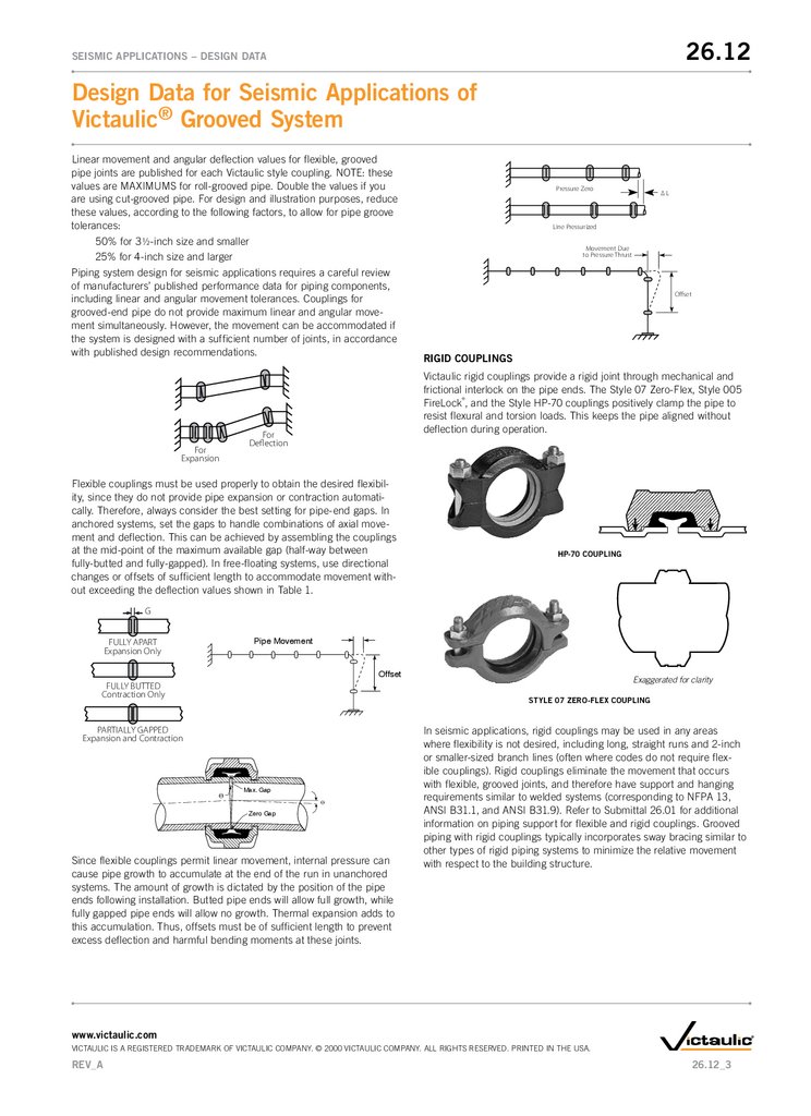
Piping system design for seismic applications requires a careful review
of manufacturers’ published performance data for piping components,
including linear and angular movement tolerances. Couplings for
grooved-end pipe do not provide maximum linear and angular movement simultaneously. However, the movement can be accommodated if
the system is designed with a sufficient number of joints, in accordance
with published design recommendations.
For
Expansion
∆L
Line Pressurized
Movement Due
to Pressure Thrust
Offset
RIGID COUPLINGS
Victaulic rigid couplings provide a rigid joint through mechanical and
frictional interlock on the pipe ends. The Style 07 Zero-Flex, Style 005
Firelock®, and the Style HP-70 couplings positively clamp the pipe to
resist flexural and torsion loads. This keeps the pipe aligned without
deflection during operation.
For
Deflection
Flexible couplings must be used properly to obtain the desired flexibility, since they do not provide pipe expansion or contraction automatically. Therefore, always consider the best setting for pipe-end gaps. In
anchored systems, set the gaps to handle combinations of axial movement and deflection. This can be achieved by assembling the couplings
at the mid-point of the maximum available gap (half-way between
fully-butted and fully-gapped). In free-floating systems, use directional
changes or offsets of sufficient length to accommodate movement without exceeding the deflection values shown in Table 1.
HP-70 COUPLING
G
Pipe Movement
FULLY APART
Expansion Only
Offset
FULLY BUTTED
Contraction Only
Exaggerated for clarity
STyLE 07 ZERO-FLEx COUPLING
PARTIALLY GAPPED
Expansion and Contraction
Θ
Max. Gap
Θ
Zero Gap
Since flexible couplings permit linear movement, internal pressure can
cause pipe growth to accumulate at the end of the run in unanchored
systems. The amount of growth is dictated by the position of the pipe
ends following installation. Butted pipe ends will allow full growth, while
fully gapped pipe ends will allow no growth. Thermal expansion adds to
this accumulation. Thus, offsets must be of sufficient length to prevent
excess deflection and harmful bending moments at these joints.
In seismic applications, rigid couplings may be used in any areas
where flexibility is not desired, including long, straight runs and 2-inch
or smaller-sized branch lines (often where codes do not require flexible couplings). rigid couplings eliminate the movement that occurs
with flexible, grooved joints, and therefore have support and hanging
requirements similar to welded systems (corresponding to nFPA 13,
AnSI B31.1, and AnSI B31.9). refer to Submittal 26.01 for additional
information on piping support for flexible and rigid couplings. grooved
piping with rigid couplings typically incorporates sway bracing similar to
other types of rigid piping systems to minimize the relative movement
with respect to the building structure.
www.victaulic.com
VICTAUlIC IS A regISTered TrAdemArk oF VICTAUlIC ComPAny. © 2000 VICTAUlIC ComPAny. All rIgHTS reSerVed. PrInTed In THe USA.
REV_A
26.12_3
4.
26.12SEISMIC APPLICATIONS – DESIGN DATA
Design Data for Seismic Applications of
Victaulic® Grooved System
SEISMIC SwING jOINT SIZING CHARTS TO DETERMINE “D”
LENGTH FOR IPS CARBON STEEL PIPE
SEISMIC MOVEMENT COMPENSATION DEVICES
D
TABLE 2A – ROLL GROOVED PIPE*
SIZE
Victaulic No. 10 90° Elbow
(6 Required)
Victaulic Flexible
Coupling
(10 Required)
Nipple “D”
(2 Required)
CL
Normal Position
Nipple Length
as Required
CL
CL
Front Elevation
Pipe Line
Pipe Line
Seismic Swing Joint Assembly
2 Ells
Nipple “D”
Nipple “D”
Coupling “B”
“A”
Fire
Sprinkler
Main
2 Ells and
Nipple “E”
2 Ells
Longitudinal Movement
Normal Position
Vertical
Movement
Fire Sprinkler Coupling
Main
“A”
Ell
Normal
Position
Ell
Normal
“B” Position
“D”
Ell
Nipple “E”
“D”
Ell
Lateral Movement
Dimensions
Minimum “D” Length – Inches/millimeters
Nom.
In.
Actual
mm
Elbow
C to E
“E”
Length
1"/
25 mm
Mvmt.
2"/
51 mm
Mvmt.
3"/
76 mm
Mvmt.
2
60.3
3.25
83
6.50
165
4
102
14
356
25
635
36
915
47
1194
57
1448
2 1/2
73.0
3.75
95
7.50
191
4
102
18
458
31
788
45
1143
58
1474
71
1804
3
88.9
4.25
108
8.50
216
4
102
22
559
37
940
53
1347
69
1753
84
2134
4
114.3
5.00
127
10.00
254
4
102
7
178
11
280
16
407
23
585
30
762
5
141.3
5.50
140
11.00
279
6
153
7
178
14
356
22
559
31
788
39
991
6
168.3
6.50
165
13.00
330
6
153
7
178
16
407
26
661
36
915
46
1169
8
219.1
7.75
197
15.50
394
6
153
9
229
22
559
35
889
49
1245
62
1575
10
273.0
9.00
229
18.00
457
8
204
14
356
31
788
48
1220
66
1677
83
2109
12
323.9
10.00
254
20.00
508
8
204
16
407
35
889
54
1372
73
1855
92
2337
6"/
5"/
4"/
102 mm 127 mm 152 mm
Mvmt.
Mvmt.
Mvmt.
*Values were calculated using standard #10 IPS cast grooved elbows. If other
elbows are used, “E” length will change accordingly.
TABLE 2B – CUT GROOVED PIPE*
SIZE
Dimensions
Minimum “D” Length – Inches/millimeters
Nom.
In.
Actual
mm
Elbow
C to E
“E”
Length
1"/
25 mm
Mvmt.
2"/
51 mm
Mvmt.
3"/
76 mm
Mvmt.
2
60.3
3.25
83
6.50
165
4
102
7
178
11
280
14
356
20
508
25
635
2 1/2
73.0
3.75
95
7.50
191
4
102
7
178
12
305
18
458
25
635
31
788
3
88.9
4.25
108
8.50
216
4
102
7
178
14
356
22
559
30
762
38
966
4
114.3
5.00
127
10.00
254
4
102
7
178
11
280
14
356
18
458
21
534
5
141.3
5.50
140
11.00
279
6
153
7
178
11
280
14
356
18
458
21
534
6
168.3
6.50
165
13.00
330
6
153
7
178
11
280
14
356
18
458
21
534
8
219.1
7.75
197
15.50
394
6
153
7
178
11
280
14
356
18
458
22
559
10
273.0
9.00
229
18.00
457
8
204
8
204
11
280
14
356
23
585
31
788
12
323.9
10.00
254
20.00
508
8
204
8
204
11
280
16
407
25
635
35
889
6"/
5"/
4"/
102 mm 127 mm 152 mm
Mvmt.
Mvmt.
Mvmt.
*Values were calculated using standard #10 IPS cast grooved elbows. If other
elbows are used, “E” length will change accordingly.
D
www.victaulic.com
VICTAUlIC IS A regISTered TrAdemArk oF VICTAUlIC ComPAny. © 2000 VICTAUlIC ComPAny. All rIgHTS reSerVed. PrInTed In THe USA.
26.12_4
REV_A
5.
26.12SEISMIC APPLICATIONS – DESIGN DATA
Design Data for Seismic Applications of
Victaulic® Grooved System
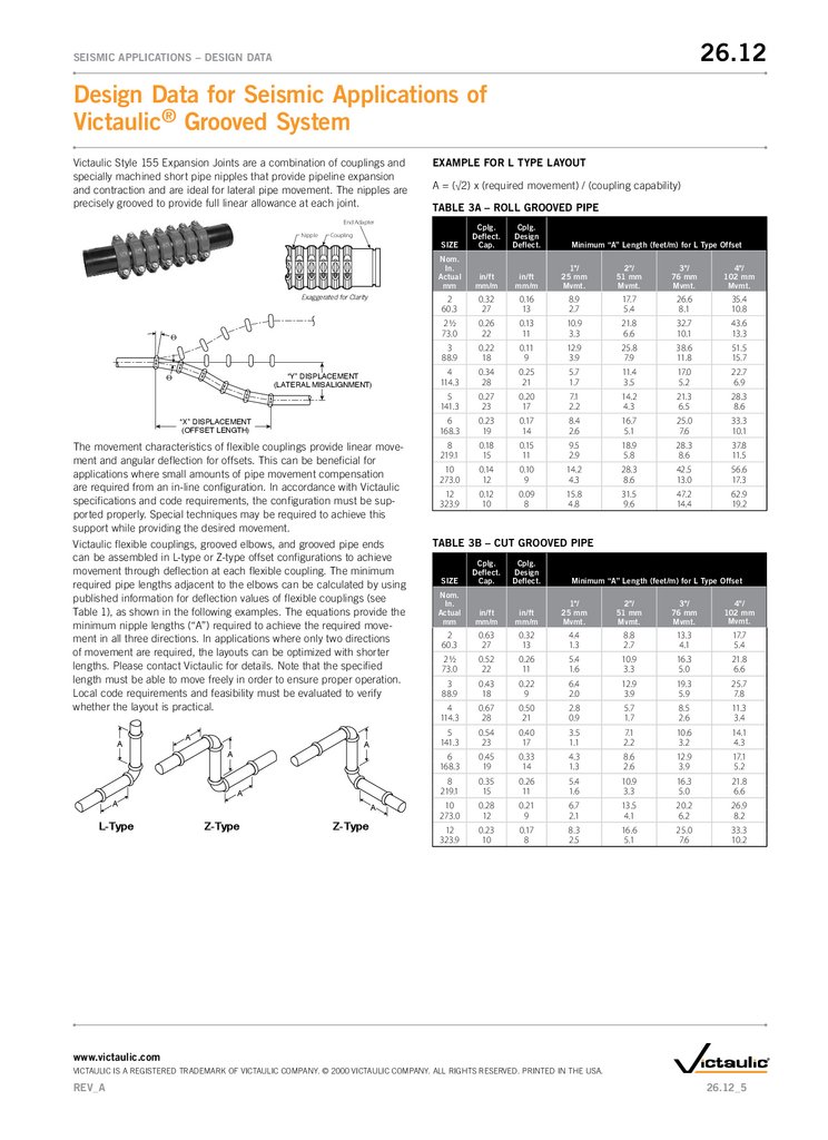
Victaulic Style 155 expansion Joints are a combination of couplings and
specially machined short pipe nipples that provide pipeline expansion
and contraction and are ideal for lateral pipe movement. The nipples are
precisely grooved to provide full linear allowance at each joint.
ExAMPLE FOR L TyPE LAyOUT
A = (√2) x (required movement) / (coupling capability)
TABLE 3A – ROLL GROOVED PIPE
End Adapter
Nipple
Exaggerated for Clarity
Θ
“Y” DISPLACEMENT
(LATERAL MISALIGNMENT)
Θ
“X” DISPLACEMENT
(OFFSET LENGTH)
The movement characteristics of flexible couplings provide linear movement and angular deflection for offsets. This can be beneficial for
applications where small amounts of pipe movement compensation
are required from an in-line configuration. In accordance with Victaulic
specifications and code requirements, the configuration must be supported properly. Special techniques may be required to achieve this
support while providing the desired movement.
Victaulic flexible couplings, grooved elbows, and grooved pipe ends
can be assembled in l-type or Z-type offset configurations to achieve
movement through deflection at each flexible coupling. The minimum
required pipe lengths adjacent to the elbows can be calculated by using
published information for deflection values of flexible couplings (see
Table 1), as shown in the following examples. The equations provide the
minimum nipple lengths (“A”) required to achieve the required movement in all three directions. In applications where only two directions
of movement are required, the layouts can be optimized with shorter
lengths. Please contact Victaulic for details. note that the specified
length must be able to move freely in order to ensure proper operation.
local code requirements and feasibility must be evaluated to verify
whether the layout is practical.
A
A
L-Type
A
A
A
A
A
Z-Type
SIZE
Cplg.
Deflect.
Cap.
Cplg.
Design
Deflect.
Nom.
In.
Actual
mm
in/ft
mm/m
in/ft
mm/m
1"/
25 mm
Mvmt.
2"/
51 mm
Mvmt.
3"/
76 mm
Mvmt.
4"/
102 mm
Mvmt.
2
60.3
0.32
27
0.16
13
8.9
2.7
17.7
5.4
26.6
8.1
35.4
10.8
2 1/2
73.0
0.26
22
0.13
11
10.9
3.3
21.8
6.6
32.7
10.1
43.6
13.3
3
88.9
0.22
18
0.11
9
12.9
3.9
25.8
7.9
38.6
11.8
51.5
15.7
4
114.3
0.34
28
0.25
21
5.7
1.7
11.4
3.5
17.0
5.2
22.7
6.9
5
141.3
0.27
23
0.20
17
7.1
2.2
14.2
4.3
21.3
6.5
28.3
8.6
6
168.3
0.23
19
0.17
14
8.4
2.6
16.7
5.1
25.0
7.6
33.3
10.1
8
219.1
0.18
15
0.15
11
9.5
2.9
18.9
5.8
28.3
8.6
37.8
11.5
10
273.0
0.14
12
0.10
9
14.2
4.3
28.3
8.6
42.5
13.0
56.6
17.3
12
323.9
0.12
10
0.09
8
15.8
4.8
31.5
9.6
47.2
14.4
62.9
19.2
Coupling
Z-Type
Minimum “A” Length (feet/m) for L Type Offset
TABLE 3B – CUT GROOVED PIPE
SIZE
Cplg.
Deflect.
Cap.
Cplg.
Design
Deflect.
Nom.
In.
Actual
mm
in/ft
mm/m
in/ft
mm/m
1"/
25 mm
Mvmt.
2"/
51 mm
Mvmt.
3"/
76 mm
Mvmt.
4"/
102 mm
Mvmt.
2
60.3
0.63
27
0.32
13
4.4
1.3
8.8
2.7
13.3
4.1
17.7
5.4
2 1/2
73.0
0.52
22
0.26
11
5.4
1.6
10.9
3.3
16.3
5.0
21.8
6.6
3
88.9
0.43
18
0.22
9
6.4
2.0
12.9
3.9
19.3
5.9
25.7
7.8
4
114.3
0.67
28
0.50
21
2.8
0.9
5.7
1.7
8.5
2.6
11.3
3.4
5
141.3
0.54
23
0.40
17
3.5
1.1
7.1
2.2
10.6
3.2
14.1
4.3
6
168.3
0.45
19
0.33
14
4.3
1.3
8.6
2.6
12.9
3.9
17.1
5.2
8
219.1
0.35
15
0.26
11
5.4
1.6
10.9
3.3
16.3
5.0
21.8
6.6
10
273.0
0.28
12
0.21
9
6.7
2.1
13.5
4.1
20.2
6.2
26.9
8.2
12
323.9
0.23
10
0.17
8
8.3
2.5
16.6
5.1
25.0
7.6
33.3
10.2
Minimum “A” Length (feet/m) for L Type Offset
www.victaulic.com
VICTAUlIC IS A regISTered TrAdemArk oF VICTAUlIC ComPAny. © 2000 VICTAUlIC ComPAny. All rIgHTS reSerVed. PrInTed In THe USA.
REV_A
26.12_5
6.
26.12SEISMIC APPLICATIONS – DESIGN DATA
Design Data for Seismic Applications of
Victaulic® Grooved System
ExAMPLE FOR Z TyPE LAyOUT
A = (required movement) / (coupling capability)
TABLE 3C – ROLL GROOVED PIPE
SIZE
Cplg.
Deflect.
Cap.
Cplg.
Design
Deflect.
Nom.
In.
Actual
mm
in/ft
mm/m
in/ft
mm/m
1"/
25 mm
Mvmt.
2"/
51 mm
Mvmt.
3"/
76 mm
Mvmt.
2
60.3
0.32
27
0.16
13
6.3
1.9
12.5
3.8
18.8
5.7
25.0
7.6
31.3
9.5
37.5
11.4
2 1/2
73.0
0.26
22
0.13
11
7.7
2.3
15.4
4.7
23.1
7.0
30.8
9.4
38.5
11.7
46.2
14.1
3
88.9
0.22
18
0.11
9
9.1
2.8
18.2
5.5
27.3
8.3
36.4
11.1
45.5
13.9
54.6
16.6
4
114.3
0.34
28
0.25
21
4.0
1.2
8.0
2.4
12.0
3.7
16.0
4.9
20.0
6.1
24.0
7.3
5
141.3
0.27
23
0.20
17
5.0
1.5
10.0
3.0
15.0
4.6
20.0
6.1
25.0
7.6
30.0
9.1
6
168.3
0.23
19
0.17
14
5.9
1.8
11.8
3.6
17.7
5.4
23.6
7.2
29.5
9.0
35.3
10.8
8
219.1
0.18
15
0.13
11
7.7
2.3
15.4
4.7
23.1
7.0
30.8
9.4
38.5
11.7
46.2
14.1
10
273.0
0.14
12
0.10
9
10.0
3.0
20.0
6.1
30.0
9.1
40.0
12.2
50.0
15.2
60.0
18.3
12
323.9
0.12
10
0.09
8
11.2
3.4
22.3
6.8
33.4
10.2
44.5
13.6
55.6
16.9
66.7
20.3
Minimum “A” Length (feet/m) for Z Type Offset
6"/
5"/
4"/
102 mm 127 mm 152 mm
Mvmt.
Mvmt.
Mvmt.
TABLE 3D – CUT GROOVED PIPE
SIZE
Cplg.
Deflect.
Cap.
Cplg.
Design
Deflect.
Nom.
In.
Actual
mm
in/ft
mm/m
in/ft
mm/m
1"/
25 mm
Mvmt.
2"/
51 mm
Mvmt.
3"/
76 mm
Mvmt.
2
60.3
0.63
53
0.32
27
3.2
1.0
6.3
1.9
9.4
2.9
12.5
3.8
15.7
4.8
18.8
5.7
2 1/2
73.0
0.52
43
0.26
22
3.9
1.2
7.7
2.3
11.6
3.5
15.4
4.7
14.5
4.4
23.1
7.0
3
88.9
0.43
36
0.22
18
4.6
1.4
9.1
2.8
13.7
4.2
18.2
5.5
22.8
6.9
27.3
8.3
4
114.3
0.67
56
0.50
42
2.0
0.6
4.0
1.2
6.0
1.8
8.0
2.4
10.0
3.0
12.0
3.7
5
141.3
0.54
45
0.40
33
2.5
0.8
5.0
1.5
7.5
2.3
10.0
3.0
12.5
3.8
15.0
4.6
6
168.3
0.45
38
0.33
28
3.1
0.9
6.1
1.9
9.1
2.8
12.2
3.7
15.2
4.6
18.2
5.5
8
219.1
0.35
29
0.26
22
3.9
1.2
7.7
2.3
11.6
3.5
15.4
4.7
19.3
5.9
23.1
7.0
10
273.0
0.28
23
0.21
18
4.8
1.5
9.6
2.9
14.3
4.4
19.1
5.8
23.9
7.3
28.6
8.7
12
323.9
0.23
19
0.17
14
5.9
1.8
11.8
3.6
17.7
5.4
23.6
7.2
29.5
9.0
35.3
10.8
Minimum “A” Length (feet/m) for Z Type Offset
6"/
5"/
4"/
102 mm 127 mm 152 mm
Mvmt.
Mvmt.
Mvmt.
SySTEM BRACING/SUPPORT GUIDELINES
G
www.victaulic.com
VICTAUlIC IS A regISTered TrAdemArk oF VICTAUlIC ComPAny. © 2000 VICTAUlIC ComPAny. All rIgHTS reSerVed. PrInTed In THe USA.
26.12_6
REV_A
7.
26.12SEISMIC APPLICATIONS – DESIGN DATA
Design Data for Seismic Applications of
Victaulic® Grooved System
Seismic separation assemblies using flexible couplings (i.e. seismic
swing joints) are typically required for all pipe sizes when the aboveground piping crosses between independently moving building segments.
our experience has shown that the first adjacent length of pipe on each
side of the grooved seismic swing joint should be rigidly attached to the
corresponding structure with adequate bracing. The swing joint must
be supported in a manner that will not prohibit proper operation during
an earthquake. non-restraining hangers should be incorporated to support the grooved elbows and pipe nipples of the assembly. noTe: Code
requirements take precedence over these recommendations.
Section 6-4.4.1 of nFPA 13 (1999) stipulates that the diameter of holes,
where pipe passes through walls or other obstructions, must be as follows:
• 2 inches larger than pipe 3 1/2 inches and smaller
• 4 inches larger than pipe 4 inches and larger.
This standard also stipulates that the piping must have at least two
inches of clearance around other structural members that are not penetrated or used to support the piping. exceptions to this include piping
that passes through gypsum or other non-fire-related material and when
flexible couplings are within 1 foot of each side of the wall or obstruction. When the applicable building code requires that the annular space
around the piping be filled, a flexible sealant, such as mastic, must be
used.
This criteria defines the method by which sprinkler systems are protected from seismic movements under nFPA 13. other piping systems
will have varying installation requirements to provide for earthquake
conditions, depending on the specific system; its proximity to seismic
zones; the level of seismic zone; and conformance to local, state, and/
or national codes. Therefore, each system must be reviewed on an
individual basis to determine the support mechanism and the proper
incorporation of flexible and rigid couplings.
Factory mutual provides design steps for sway bracing in data Sheet
2-8, earthquake Protection for Water-based Fire Protection Systems,
which states the following:
Step 1: Lay out sway bracing locations with respect to the sprinkler piping and to the structural members to which the bracing will be attached.
Step 2: Calculate the seismic design load requirements for each sway
bracing location.
Step 3: Select the proper sway bracing shape, angle of attachment, size,
and maximum length based on the horizontal design load requirement.
Step 4: Select the proper attachment method for the sway bracing to the
structure and to the piping.1
Systems installed with Victaulic rigid couplings can be supported and
braced for seismic occurrences in a similar way to threaded and welded
systems. The hanger spacing requirements for Victaulic rigid couplings
are in accordance with standard industry codes for threaded and
welded systems. These nationally recognized codes are AnSI B31.1
Power Piping Code, AnSI B31.9 Building Services Code and nFPA 13
Sprinkler Systems.
Victaulic Company’s pipe support recommendations for both flexible
and rigid systems can be found in the following Tables 4A through 4C.
The tables show the suggested maximum span between pipe supports
for horizontal straight runs of standard-weight steel pipe that carry water
or similar liquids.
RIGID SySTEMS
For Victaulic rigid coupling Styles 07, 307, HP-70, 005, and others,
the Maximum Hanger Spacing below may be used.
TABLE 4A
Suggested Maximum Span Between Supports
Feet/meters
PIPE SIZE
Nominal
Inches
Actual mm
*
†
‡
*
†
‡
1
33.7
1 1/4
42.4
1 1/2
48.3
2
60.3
3
88.9
4
114.3
6
168.3
8
219.1
10
273.0
12
323.9
14
355.6
16
406.4
18
457.0
20
508.0
24
610.0
7
2.1
7
2.1
7
2.1
10
3.1
12
3.7
14
4.3
17
5.2
19
5.8
19
5.8
23
7.0
23
7.0
27
8.2
27
8.2
30
9.1
32
9.8
9
2.7
11
3.4
12
3.7
13
4.0
15
4.6
17
5.2
20
6.1
21
6.4
21
6.4
21
6.4
21
6.4
21
6.4
21
6.4
21
6.4
21
6.4
12
3.7
12
3.7
15
4.6
15
4.6
15
4.6
15
4.6
15
4.6
15
4.6
15
4.6
15
4.6
15
4.6
15
4.6
15
4.6
15
4.6
15
4.6
9
2.7
9
2.7
9
2.7
13
4.0
15
4.6
17
5.2
21
6.4
24
7.3
24
7.3
30
9.1
30
9.1
35
10.7
35
10.7
39
11.9
42
12.8
9
2.7
11
3.4
13
4.0
15
4.6
17
5.2
21
6.4
25
7.6
28
8.5
31
9.5
33
10.1
33
10.1
33
10.1
33
10.1
33
10.1
33
10.1
12
3.7
12
3.7
15
4.6
15
4.6
15
4.6
15
4.6
15
4.6
15
4.6
15
4.6
15
4.6
15
4.6
15
4.6
15
4.6
15
4.6
15
4.6
water Service
Gas or Air Service
* Spacing corresponds to ANSI B31.1 Power Piping Code.
† Spacing corresponds to ANSI B31.9 Building Services Piping Code.
‡ Spacing corresponds to NFPA 13 Sprinkler Systems.
FLExIBLE SySTEMS
For coupling Styles including 75, 77, and others.
Standard, grooved-type couplings allow angular, linear, and rotational
movement at each joint to accommodate expansion, contraction, settling, vibration, noise, and other piping system movement. These features provide advantages in designing piping systems but must be considered when determining hanger and support bracing and location.
www.victaulic.com
VICTAUlIC IS A regISTered TrAdemArk oF VICTAUlIC ComPAny. © 2000 VICTAUlIC ComPAny. All rIgHTS reSerVed. PrInTed In THe USA.
REV_A
26.12_7
8.
26.12SEISMIC APPLICATIONS – DESIGN DATA
Design Data for Seismic Applications of
Victaulic® Grooved System
Maximum Hanger Spacing
For straight runs without concentrated loads and where full linear
movement is required.
TABLE 4B
PIPE SIZE
ENERGIZED, UNANCHORED
Pipe Length in Feet/meters
7
2.1
Nominal
Inches
Actual mm
10
3.0
12
3.7
15
4.6
20
6.1
22
6.7
25
7.6
30
9.1
35
10.7
40
12.2
*Average Hangers per Pipe Length Evenly Spaced
3/4 – 1
26.9 – 33.7
1 1/4 – 2
42.4 – 60.3
2 1/2 – 4
73.0 – 114.3
5–8
141.3 – 219.1
10 – 12
273.0 – 323.9
14 – 16
355.6 – 406.4
18 – 24
457.0 – 610.0
28 – 42
711.0 – 1067.0
1
2
2
2
3
3
4
4
5
6
1
2
2
2
3
3
4
4
5
5
1
1
2
2
2
2
2
3
4
4
1
1
1
2
2
2
2
3
3
3
1
1
1
2
2
2
2
3
3
3
1
1
1
2
2
2
2
3
3
3
1
1
1
2
2
2
2
3
3
3
1
1
1
1
2
2
2
3
3
3
L
No anchor on horizontal pipe movement
will be towards path of least resistance.
ANCHORED BOTH ENDS
A
Maximum Hanger Spacing
For straight runs without concentrated loads and where full linear
movement is not required.
B
PT
TABLE 4C
Suggested Maximum Span
Between Supports
Feet/meters
3/4 – 1
26.9 – 33.7
8
2.4
1 1/4 – 2
42.4 – 60.3
10
3.0
2 1/2 – 4
73.0 – 114.3
12
3.7
5–8
141.3 – 219.1
14
4.3
10 – 12
273.0 – 323.9
16
4.9
14 – 16
355.6 – 406.4
18
5.5
18 – 30
457.0 – 762.0
20
6.1
32 – 42
813.0 – 1067.0
21
6.4
∆L
- Victaulic flexible coupling
- Anchor
- Assumed or proposed anchor
*No pipe length should be left unsupported between any two couplings.
PIPE SIZE RANGE
Nominal Inches
Actual mm
ANCHOR ONE SIDE
PT
Unrestrained, deflected joints will straighten under axial pressure thrusts
and other forces that act to pull pipes apart. If deflection is desired,
anchors or lateral resistance must be applied to the lines to help maintain joint deflection. lateral forces will always act upon deflected joints
due to internal pressure. A fully-deflected joint will not provide linear
movement that is normally available at the joint. Conversely, angular
deflection at fully-butted or fully-gapped joints is not possible, unless
the pipe ends can shorten and grow, as required. Partially deflected
joints will provide some portion of linear movement.
Plan View
(Zero Pressure)
Plan View
(Pressurized)
The system designer should note that flexible couplings installed with
partial gaps or fully-butted pipe ends will allow the pipe to expand fully
when the system is energized. Strategically placed anchors will contain the energized system between the anchors. Also, pipe guides and
proper pipe support will help to prevent angular deflection at the joints
that would otherwise reduce the amount of linear movement capable at
each joint.
Hanger
Lateral
Force
Gross effect of
inadequate lateral
restraint on suspended system.
(illustration exaggerated for clarity)
ANCHORED BOTH ENDS
INITIAL
B
C
D
Flexible couplings can provide deflection at branch connections and
offsets to accommodate anticipated pipe movement. Offsets must be
www.victaulic.com
VICTAUlIC IS A regISTered TrAdemArk oF VICTAUlIC ComPAny. © 2000 VICTAUlIC ComPAny. All rIgHTS reSerVed. PrInTed In THe USA.
26.12_8
REV_A
9.
26.12SEISMIC APPLICATIONS – DESIGN DATA
Design Data for Seismic Applications of
Victaulic® Grooved System
long enough to provide sufficient deflection to prevent harmful bending
moments, which would be induced at the joints of the offset. noTe:
If the pipes were to expand due to thermal changes, additional pipe
growth would also take place at the ends.
SEISMIC CALCULATIONS
Victaulic grooved products have consistently demonstrated the ability
to withstand considerable forces during earthquakes. When exposed
to bending forces, they have remained intact. A bending moment will
occur when the joint deflects beyond its maximum allowable angular
deflection. Where these deflections are anticipated, additional flexible
couplings should be installed to accommodate this movement. Several
agencies, such as ASTm and Underwriters laboratories (Ul), have
established methods for qualification of bending loads. However, the following is a list of the minimum bending moments that Victaulic products
must withstand to obtain a Ul listing. Ul established the minimum
bending moment requirements through the following method from Ul
Standard 213, rubber gasketed Fittings for Fire Protection:
The bending moments are calculated based on twice the weight of the
water filled pipe over twice the maximum distance between supports
specified in the Standard for Installation of Sprinkler Systems, nFPA 13.2
This Ul standard is one of several publications for bending moment
requirements. ASTm F-1476 is another standard that provides bending
loads based on hanger spacing, etc. The couplings are tested only to
the respective bending moment shown, and factor of safety is built into
these values. All bending moments were applied at their maximum Ul
pressure rating. These values are provided as information only and must
not be used for design purposes. However, they can be compared to
minimum theoretical values required by various building codes to demonstrate the actual capabilities versus design requirements.
MINIMUM REQUIRED BENDING MOMENT AT COUPLING ON
STANDARD wALL PIPE
California Building Code. Section 1630B.2 states that piping, ducting,
conduit systems, and connections that are constructed of ductile materials may use the values of Cp from Table 16B-0. Victaulic grooved coupling housings are constructed of durable ductile iron that is dual certified to ASTm A395, grade 65-45-15 and ASTm A536, grade 65-45-12.
ASTm A395 is the formulation commonly referenced in ASTm B31
codes for ductile iron pressure-containing components, while ASTm
A536 is a widely accepted formulation used in modern castings.
INTERNATIONAL BUILDING CODE (2000)
Seismic forces calculated in accordance with IBC are determined as follows:
lp
F p = (0.4apSDSWp ) R
p
(
z
1+2 h
)
which can be simplified to the following equation based on the maximum value of Fp:
F p = 1.6DS1 pWp
where
Fp is the design lateral force for non-structural components.
SdS is design spectral response acceleration (0.33, based on SdS =
2FaSs/3, where Fa = 2.5 for worst case soft soil and Ss = 0.2s for worst
case spectral acceleration).
Ip is importance factor (1.5 for critical facility).
Wp is component operating weight.
When required, the vertical component of the force is calculated by:
F p v = 0.25DSWp
The following chart provides results using the first simplified equation as
a general case.
STANDARD wALL CARBON STEEL PIPE SINGLE SPAN, SIMPLE SUPPORT
TABLE 6
TABLE 5
COUPLING SIZE
Nominal In.
Actual mm
Bending Moment
ft-lb
N•m
COUPLING SIZE
Nominal In.
Actual mm
Bending Moment
ft-lb
N•m
1
33.7
300
407
6
168.3
7085
9600
1 1/4
42.4
420
569
8
219.1
11304
15317
1 1/2
48.3
810
1098
10
273.0
16785
22744
2
60.3
1150
1558
12
323.9
22950
31098
2 1/2
73.0
1770
2398
14
355.6
27450
37195
3
88.9
2426
3287
16
4006.4
35843
48568
3 1/2
101.6
3013
4083
18
457.0
45360
61463
4
114.3
3645
4939
20
508.0
54742
74176
5
141.3
5238
7098
24
610.0
77670
105244
The following static analysis equations and resulting values demonstrate
the capabilities of Victaulic products in seismic conditions. The results
provided in the following tables show that properly assembled Victaulic
grooved couplings exceed the performance requirements to which
threaded and welded piping systems currently conform for use in preapproved seismic systems. In addition, Victaulic has a 75-year history of
successful use of these products in commercial building applications,
mining, municipal, industrial, oilfield, and fire protection. These results
are in accordance with the requirements of the latest revision of the
SIZE
Nominal In.
Actual mm
wp
lb/ft
kg/m
Fp
lb/ft
kg/m
M
ft-lb
N•m
2
60.3
5.1
7.6
4.0
6.0
800
1084
1.44
2 1/2
73.0
7.9
11.8
6.3
9.4
1260
1707
1.41
3
88.9
10.8
16.1
8.6
12.8
1720
2331
1.41
4
114.3
16.3
24.3
12.9
19.2
2580
3496
1.41
6
168.3
31.5
46.9
25.0
37.2
5000
6775
1.42
8
219.1
50.2
74.7
39.8
59.2
7960
10786
1.42
10
273.0
74.6
111.0
59.1
87.9
11820
16016
1.42
12
323.9
98.6
146.7
78.1
116.2
15620
21165
1.47
14
355.6
114.3
170.1
90.5
134.7
18100
24526
1.52
16
406.4
141.7
210.8
112.2
167.0
22440
30407
1.60
18
457.0
171.8
255.6
136.1
202.5
27220
36884
1.67
20
508.0
204.6
304.4
162.0
241.1
32400
43902
1.69
24
610.0
278.4
414.3
220.5
328.1
44100
59756
1.76
Safety
Factor*
*Safety factor is based on comparison of calculated bending moment (M) to
UL minimum required bending moment which all Listed Victaulic couplings
must withstand.
www.victaulic.com
VICTAUlIC IS A regISTered TrAdemArk oF VICTAUlIC ComPAny. © 2000 VICTAUlIC ComPAny. All rIgHTS reSerVed. PrInTed In THe USA.
REV_A
26.12_9
10.
26.12SEISMIC APPLICATIONS – DESIGN DATA
Design Data for Seismic Applications of
Victaulic® Grooved System
CALIFORNIA BUILDING CODE (BASED ON 1997 UNIFORM
BUILDING CODE)
I is importance factor (1.5 based on essential facility).
F p = 0.4 Ca 1p Wp
or, to consider the higher accelerations which occur on upper elevations
of a structure,
F p = (ap Ca 1p / Rp ) (1 + 3h x / hr ) Wp
where
Fp is the design lateral force for nonstructural components.
ap is component amplification factor (1.0 for piping).
Ca is the seismic coefficient (between 0.06 and 0.44, depending on
seismic acceleration zone and soil profile).
Ip is the importance factor (1.5 for essential facility).
rp is the response modification factor (3.0 for piping).
hx is component elevation (components on upper elevations receive
more accelerations than lower floors).
hr is roof elevation.
Wp is distributed load of the pipe (weight per foot of pipe and water).
The following chart provides results using the first equation as a general
case, with Ca of 0.44 (worst case) and Ip of 1.5.
STANDARD wALL CARBON STEEL PIPE
SINGLE SPAN, SIMPLE SUPPORT
TABLE 7
SIZE
Nominal In.
Actual mm
wp
lb/ft
kg/m
Fp
lb/ft
kg/m
M
ft-lb
N•m
2
60.3
2 1/2
73.0
3
88.9
4
114.3
6
168.3
8
219.1
10
273.0
12
323.9
14
355.6
16
406.4
18
457.0
20
508.0
24
610.0
5.1
7.6
7.9
11.8
10.8
16.1
16.3
24.3
31.5
46.9
50.2
74.7
74.6
111.0
98.6
146.7
114.3
170.1
141.7
210.8
171.8
255.6
204.6
304.4
278.4
414.3
1.4
2.1
2.1
3.1
2.9
4.3
4.3
6.4
8.3
12.4
13.3
19.8
19.7
29.3
26.0
38.7
30.2
44.9
37.4
55.7
45.4
67.6
54.0
80.4
73.5
109.4
270
366
418
566
570
772
860
1165
1664
2255
2650
3591
3938
5336
5206
7054
6036
8179
7482
10138
9072
12293
10802
14637
14700
19919
Safety
Factor*
4.26
4.23
4.26
3.50
4.26
Cp is horizontal force factor (0.75 for rigidly mounted pipe). (noTe: resiliently mounted equipment, such as spring-mounted hangers, uses a Cp
of 2.0).
W is distributed load (weight per foot of pipe and water).
STANDARD wALL CARBON STEEL PIPE SINGLE SPAN, SIMPLE
SUPPORT
TABLE 8
SIZE
Nominal In.
Actual mm
wp
lb/ft
kg/m
Fp
lb/ft
kg/m
M
ft-lb
N•m
2
60.3
21/2
73.0
3
88.9
4
114.3
6
168.3
8
219.1
10
273.0
12
323.9
14
355.6
16
406.4
18
457.0
20
508.0
24
610.0
5.1
7.6
7.9
11.8
10.8
16.1
16.3
24.3
31.5
46.9
50.2
74.7
74.6
111.0
98.6
146.7
114.3
170.1
141.7
210.8
171.8
255.6
204.6
304.4
278.4
414.3
2.3
3.4
3.5
5.2
4.9
7.3
7.3
10.9
14.2
21.1
22.6
33.6
33.6
50.0
44.4
66.1
51.4
76.5
63.8
94.9
77.31
115.0
92.07
137.0
125.29
186.4
460
623
708
959
970
1314
1467
1988
2833
3839
4522
6127
6712
9095
8871
12020
10285
13936
12752
17279
15461
20950
18414
24951
25058
33954
Safety
Factor*
2.50
2.50
2.50
2.48
2.50
2.50
2.50
2.58
2.66
2.81
2.93
2.97
3.10
*Safety factor is based on comparison of calculated bending moment (M) to
UL minimum required bending moment which all Listed Victaulic couplings
must withstand.
4.27
4.26
4.41
4.55
4.79
5.00
5.07
SEISMIC TESTING OF VICTAULIC PRODUCTS
The performance of the Victaulic grooved-end piping system under seismic conditions was evaluated in a series of tests conducted by AnCo
engineers, Inc., an independent laboratory that specializes in seismic
evaluations of products. The tests were conducted to assess the structural and functional integrity of Victaulic products during seismic loading
for a major electric utility that was considering the use of grooved piping
at one of its nuclear plant sites. The tests included flexible and rigid
couplings, tees, elbows, reducers, and caps, as well as roll-grooved and
cut-grooved pipe in 1 – 6-inch nominal sizes.
5.28
*Safety factor is based on comparison of calculated bending moment (M) to
UL minimum required bending moment which all Listed Victaulic couplings
must withstand.
Y
1999 ASHRAE (BASED ON 1994 UNIFORM BUILDING CODE)
F p = Z I Cp W
where
Fp is total design lateral seismic force (actually recalculates distributed
load for piping system).
IN
MA "
ED 1'0
FE EV.
EL
Z
X
TEST SYSTEM A
Figure 1
Z is seismic zone factor (0.4 based upon worse case seismic zone 4).
www.victaulic.com
VICTAUlIC IS A regISTered TrAdemArk oF VICTAUlIC ComPAny. © 2000 VICTAUlIC ComPAny. All rIgHTS reSerVed. PrInTed In THe USA.
26.12_10
REV_A
11.
26.12SEISMIC APPLICATIONS – DESIGN DATA
Design Data for Seismic Applications of
Victaulic® Grooved System
TABLE 9
Operating-Basis
Earthquake (OBE) Tests
Y
IN
MA
ED '0"
FE EV. 2
EL
Z
x
y
Z
x
y
Z
x
y
Z
1.9
3.1
1.4
2.6
4.7
2.4
3.1
5.0
3.3
B
1.5
6.9
3.5
2.3
8.9
5.0
2.9
14.1
5.4
C
2.4
0.9
2.6
3.9
1.4
5.0
4.0
1.4
4.0
A
X
TEST SYSTEM B
Figure 2
The 6.9g y-direction result for System B during oBe testing reflected
the use of a hard stop on the piping to simulate lack of rattle space
near that location. Additionally, the highest-level test produced displacements in System B of +/-5.0” in the X direction and +1.6”/-6.0” in the
y direction. The previously mentioned hard stop limited the +y direction displacement. The same test displaced System C +/-0.35” in the X
direction and +/-3.5” in the y direction.
100.00
TABLE INPUT X
G's
X
Figure 3
The laboratory used computerized data monitoring control and acquisition systems, plus servo-hydraulic actuators and feedback controls to
conduct the tests. Three test segments (A, B, and C shown in figures
1, 2, and 3) were constructed on a shake table that measured 45-feet
long by 14-feet wide and 14-feet high. Four linked actuators – two longitudinal and two transverse units – generated the pitch, roll, and yaw
motions of earthquake activity.
each simulated disturbance lasted 30 seconds, including a 5-second
rise, 20 seconds of strong motion, and 5 seconds of delay time.
The tests simulated 13 different scenarios:
• Three less-than-operating-basis earthquakes (oBe) to establish
the relationship between shake table drive signal gains and computed test response spectra (TrS)
• Six oBes
• Two safe-shutdown earthquakes (SSe)
• An earthquake scaled to 1.2 times SSe levels
• one scaled to 1.4 times SSe levels
The test system main feed line resonant frequencies ranged from 1.92
Hz (y direction) to 40.6 Hz (Z direction). Shake-table input acceleration
averaged 1.5g in each principal direction during the oBe tests, 2.25g
during the SSe tests, and 2.9g under the highest-level (H-l) conditions
(upward ground accelerations of up to 1.8g were recorded during the
northridge earthquake). The following table shows response accelerations in “g”s for the main feed lines of systems A, B, and C in directions
X, y, and Z during oBe, SSe, and H-l testing. These results apply only
to Victaulic products and do not represent the performance capabilities
of competitors’ grooved products.
10.000
RESPONSE
TEST SYSTEM C
1.0000
Figure 4
.10000
1.0000
100.00
10.000
FREQUENCY IN HERTZ
TABLE INPUT X
100.00
G's
10.000
RESPONSE
Z
PSEUDO ACCELER G
Y
PSEUDO ACCELER G
IN
MA
ED . 3'0"
E
F EV
EL
Highest Level
(H-L)
Tests
Safe-Shutdown
Earthquake (SSE) Tests
1.0000
Figure 5
.10000
1.0000
10.000
FREQUENCY IN HERTZ
100.00
www.victaulic.com
VICTAUlIC IS A regISTered TrAdemArk oF VICTAUlIC ComPAny. © 2000 VICTAUlIC ComPAny. All rIgHTS reSerVed. PrInTed In THe USA.
REV_A
26.12_11
12.
26.12GROOVED PIPING SySTEM – DESIGN DATA
Design Data for Seismic Applications of
Victaulic® Grooved System
TABLE INPUT X
SEISMIC COMPATIBLE CONFIGURATION CAN BE EASILy
INSULATED.
G's
10.000
RESPONSE
PSEUDO ACCELER G
100.00
1.0000
Figure 6
.10000
1.0000
10.000
FREQUENCY IN HERTZ
100.00
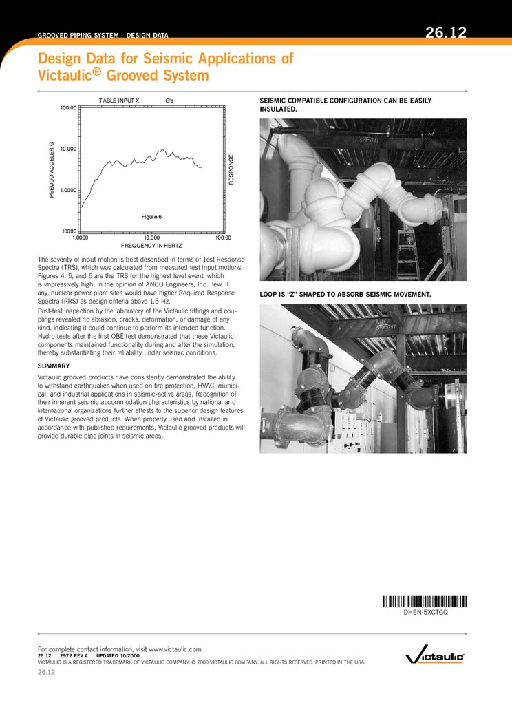
The severity of input motion is best described in terms of Test response
Spectra (TrS), which was calculated from measured test input motions.
Figures 4, 5, and 6 are the TrS for the highest level event, which
is impressively high. In the opinion of AnCo engineers, Inc., few, if
any, nuclear power plant sites would have higher required response
Spectra (rrS) as design criteria above 1.5 Hz.
Post-test inspection by the laboratory of the Victaulic fittings and couplings revealed no abrasion, cracks, deformation, or damage of any
kind, indicating it could continue to perform its intended function.
Hydro-tests after the first oBe test demonstrated that these Victaulic
components maintained functionality during and after the simulation,
thereby substantiating their reliability under seismic conditions.
LOOP IS “Z” SHAPED TO ABSORB SEISMIC MOVEMENT.
SUMMARy
Victaulic grooved products have consistently demonstrated the ability
to withstand earthquakes when used on fire protection, HVAC, municipal, and industrial applications in seismic-active areas. recognition of
their inherent seismic accommodation characteristics by national and
international organizations further attests to the superior design features
of Victaulic grooved products. When properly used and installed in
accordance with published requirements, Victaulic grooved products will
provide durable pipe joints in seismic areas.
DHEN-5XCTGQ
For complete contact information, visit www.victaulic.com
26.12
2972 REV A
UPDATED 10/2000
VICTAUlIC IS A regISTered TrAdemArk oF VICTAUlIC ComPAny. © 2000 VICTAUlIC ComPAny. All rIgHTS reSerVed. PrInTed In THe USA.
26.12