


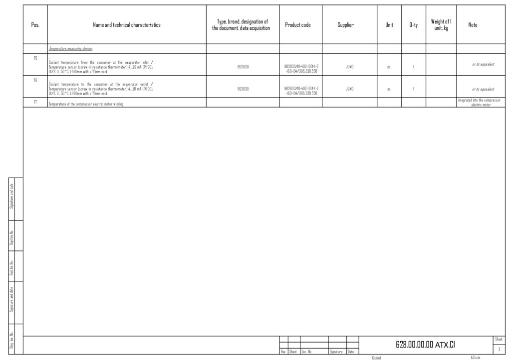


 Construction
Similar presentations:


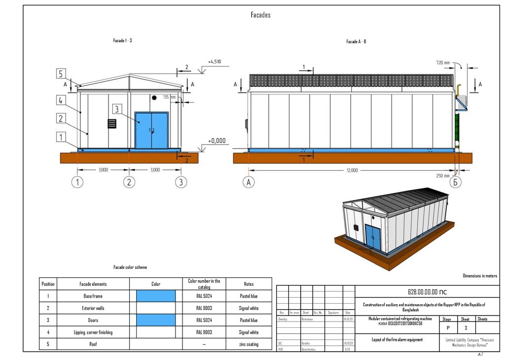
Facade color scheme
1.
FacadesFacade 1 - 3
Facade A - B
Facade color scheme
Color
Dimensions in meters
Color number in the
catalog
Notes
Position
Facade elements
1
Base frame
RAL 5024
Pastel blue
2
Exterior walls
RAL 9003
Signal white
3
Doors
RAL 5024
Pastel blue
4
Lipping, corner finishing
RAL 9003
Signal white
5
Roof
—
zinc coating
628.00.00.00 ПС
Rev.
Develop.
Rev. areas. Sheet
Doc. No.
Romanova
Signature:
Date
16.10.23
QC
Korytko
16.10.23
PCE
Demchenkov
9.23
Construction of auxiliary and maintenance objects at the Ruppur NPP in the Republic of
Bangladesh
Modular containerized refrigerating machine
КХМ-DCLCDX72DX73DK8EC58
Layout of the fire alarm equipment
Stage
Sheet
Р
3
Sheets
Limited Liability Company "Precision
Mechanics Design Bureau"
А3
2.
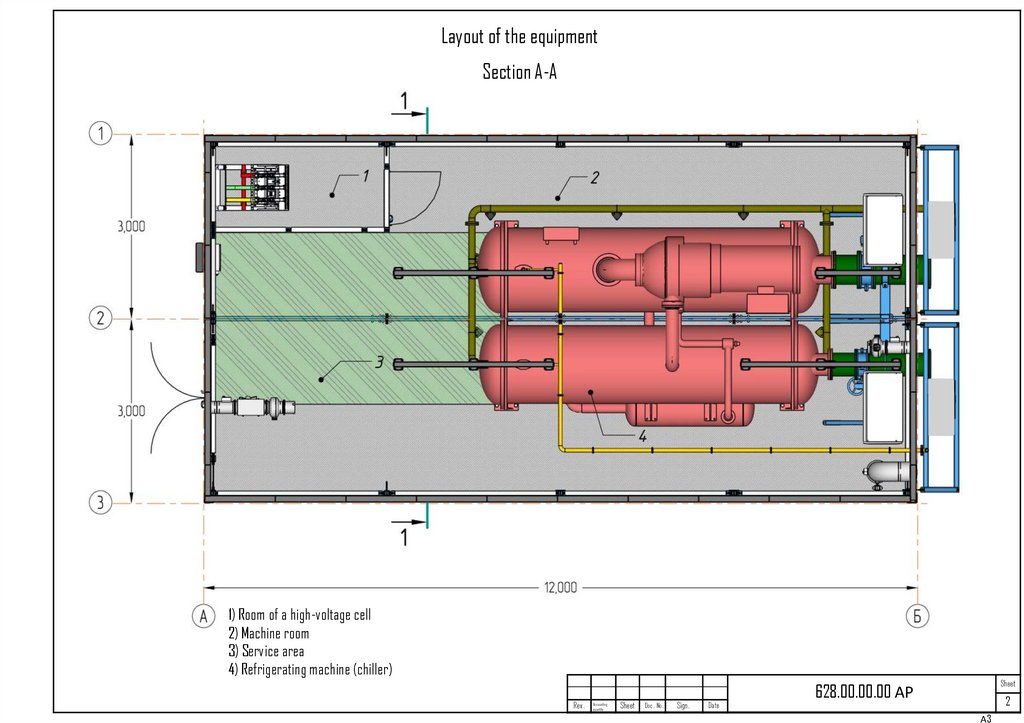
Layout of the equipmentSection A-A
1) Room of a high-voltage cell
2) Machine room
3) Service area
4) Refrigerating machine (chiller)
Rev.
Accounting
quantity
Sheet
Doc. No.
Sign.
Date
Sheet
628.00.00.00 АР
2
А3
3.
Enclosing structures, frameworkSection 1-1
1) Three-layer metal panels with mineral wool insulation according to GOST 32603-2012. S-100 mm
2) Structural floor cavities filled with non-flammable insulation based on mineral wool according to GOST 9573-2012
3) Frame of the block box is welded with bolted connections from a profile pipe 80x80x6 according to GOST 8639-82
4) Frame base is welded from steel channels according to GOST 8240-97
Rev.
Accounting
quantity
Sheet
Doc. No.
Sign.
Date
Sheet
628.00.00.00 АР
3
А3
4.
Enclosing structures, frameworkSection 2-2
1) Three-layer metal panels with mineral wool insulation according to GOST 32603-2012. S-100 mm
2) Structural floor cavities filled with non-flammable insulation based on mineral wool according to GOST 9573-2012
3) Frame of the block box is welded with bolted connections from a profile pipe 80x80x6 according to GOST 8639-82
4) Frame base is welded from steel channels according to GOST 8240-97
Rev.
Accounting
quantity
Sheet
Doc. No.
Sign.
Date
Sheet
628.00.00.00 АР
4
А3
5.
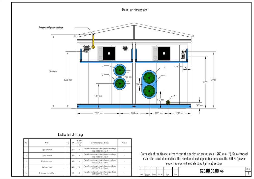
Mounting dimensionsEmergency refrigerant discharge
Explication of fittings
Pos.
Name
Q-ty
DN
Nominal
pressure
, MPa
Connection type and standard
Material
1
Capacitor output
1
350
1.0
Flanged connection with a mating flange according to
GOST 33259-2015. Type 11
-
2
Capacitor intput
1
350
1.0
Flanged connection with a mating flange according to
GOST 33259-2015. Type 11
-
3
Evaporator output
1
450
1.0
Flanged connection with a mating flange according to
GOST 33259-2015. Type 11
-
4
Evaporator input
1
450
1.0
Flanged connection with a mating flange according to
GOST 33259-2015. Type 11
-
1.0
Flanged connection with a mating flange according to
GOST 33259-2015. Type 11
-
5
Drainage system outflow
1
100
Outreach of the flange mirror from the enclosing structures - 250 mm (*). Conventional
size - thr exact dimensions, the number of cable penetrations, see the PSEEL (power
supply equipment and electric lighting) section
Rev.
Accounting
quantity
Sheet
Doc. No.
Sign.
Date
628.00.00.00 АР
Sheet
4
6.
First applicationRef.No.
Dupl.Inv.No.
Signature and date
Repl.Inv.No. .
Pipe support350
Pipe support450
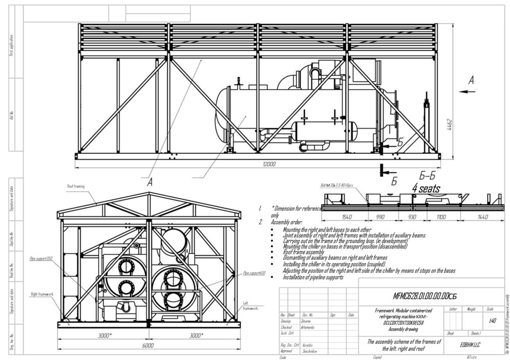
* Dimension for reference
only
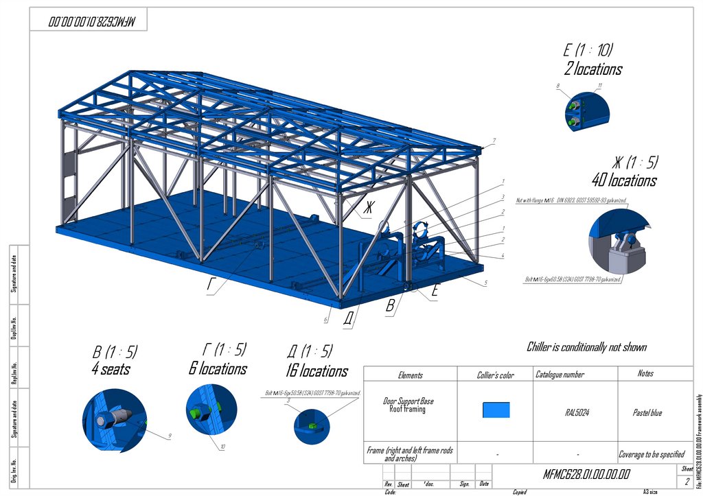
Assembly order:
• Mounting the right and left bases to each other
• Joint assembly of right and left frames with installation of auxiliary beams.
• Carrying out on the frame of the grounding loop. (in development)
• Mounting the chiller on bases in transport position (disassembled)
• Roof frame assembly
• Dismantling of auxiliary beams on right and left frames
• Installing the chiller in its operating position (coupled).
Adjusting the position of the right and left side of the chiller by means of stops on the bases
• Installation of pipeline supports
MFMC628.01.00.00.00СБ
Right framework.
Left
framework.
Rev. Sheet
Develop.
Checked
Tech. Ctrl
Doc. No.
Zimarev
Artemenko
Reg. Doc. Ctrl Korytko
Approved
Svechnikov
Code:
Sign.
Date
Framework. Modular containerized
refrigerating machine КХМDCLCDX72DX73DK8EC58
Assembly drawing
The assembly scheme of the frames of
the left, right and roof
Copied
Letter
Weight
Scale
1:40
Sheet
Sheets 1
EDBHM LLC
A3 size
File: MFMC628.01.00.00.00 Framework assembly
Signature and date
1.
2.
Orig. Inv. No.
4 seats
Bolt М30х3.5-80-16pcs
Roof framing
7.
MFMC628.01.00.00.002 locations
40 locations
Signature and date
Nut with flange М16 DIN 6923, GOST 59592-93 galvanized.
Chiller is conditionally not shown
4 seats
6 locations
16 locations
Elements
Bolt М16-6gx50.58 (S24) GOST 7798-70 galvanized.
3
Door Support Base
Collier's color
Roof framing
Frame (right and left frame rods
and arches)
Rev. Sheet
Code:
¹ doc.
Sign.
Notes
Catalogue number
RAL5024
Pastel blue
-
Coverage to be specified
Sheet
MFMC628.01.00.00.00
Date
Copied
2
A3 size
File: MFMC628.01.00.00.00 Framework assembly
Orig. Inv. No.
Signature and date
Repl.Inv.No.
Dupl.Inv.No.
Bolt М16-6gx60.58 (S24) GOST 7798-70 galvanized.
8.
MFMC628.01.01.03.00КМSignature and date
Ref. No.
First application
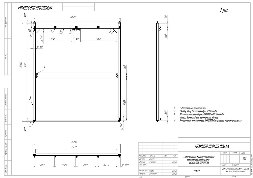
1 pc.
Dupl.Inv.No.
1.
2.
3.
MFMC628.01.01.03.00КМ
Letter
Rev. Sheet
Develop.
Checked
Tech. Ctrl
Doc. No.
Zimarev
Artemenko
Sign.
Date
29.09.23
Reg. Doc. Ctrl Korytko
29.09.23
Approved
Code:
29.09.23
Svechnikov
Left framework. Modular refrigeration
containerized machine КХМDCLCDX72DX73DK8EC58
Arch 1
Copied
Weight
Scale
1:20
Sheet
Pages 1
LIMITED LIABILITY COMPANY "PRECISION
MECHANICS DESIGN BUREAU"
A3 size
File: MFMC628.01.01.03.00 Arch 1
Orig. Inv. No.
Signature and date
Repl.Inv.No.
4.
* Dimension for reference only
Welding along the mating edges of the parts.
Welded seams according to GOST5264-80. Clean the
seams. Burns and non-welds are not allowed.
For corrosion protection see MFMC628.Flow process diagram of coatings
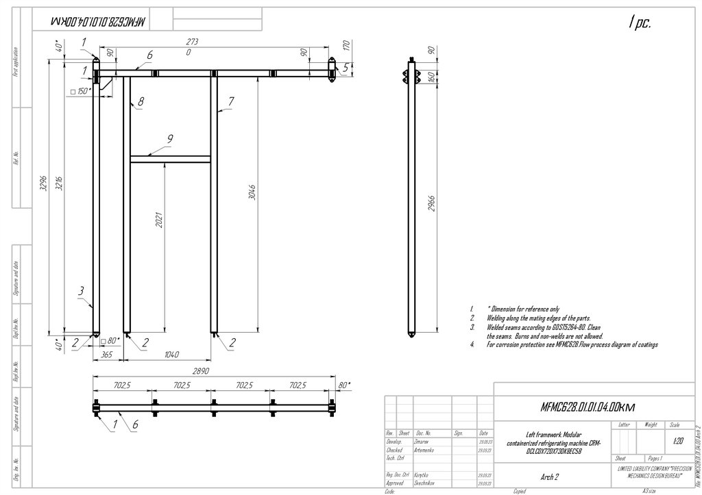
9.
1 pc.Signature and date
Ref. No.
First application
MFMC628.01.01.04.00КМ
Dupl.Inv.No.
1.
2.
3.
MFMC628.01.01.04.00КМ
Letter
Rev. Sheet Doc. No.
Develop.
Zimarev
Checked
Artemenko
Tech. Ctrl
Sign.
Date
29.09.23
29.09.23
Reg. Doc. Ctrl Korytko
29.09.23
Approved
Code:
29.09.23
Svechnikov
Left framework. Modular
containerized refrigerating machine CRMDCLCDX72DX73DK8EC58
Arch 2
Copied
Weight
Scale
1:20
Sheet
Pages 1
LIMITED LIABILITY COMPANY "PRECISION
MECHANICS DESIGN BUREAU"
A3 size
File: MFMC628.01.01.04.00 Arch 2
Orig. Inv. No.
Signature and date
Repl.Inv.No.
4.
* Dimension for reference only
Welding along the mating edges of the parts.
Welded seams according to GOST5264-80. Clean
the seams. Burns and non-welds are not allowed.
For corrosion protection see MFMC628.Flow process diagram of coatings
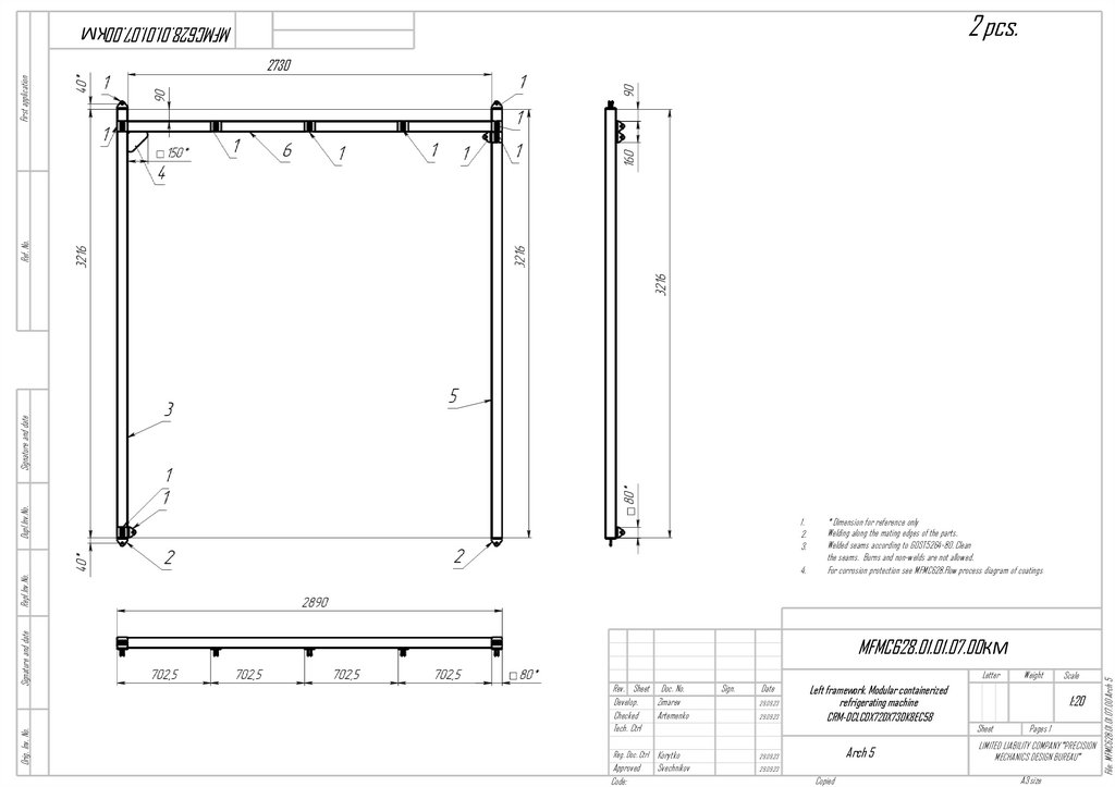
10.
2 pcs.MFMC628.01.01.07.00КМ
Dupl.Inv.No.
Signature and date
Ref. No.
First application
2730
1.
2.
3.
MFMC628.01.01.07.00КМ
Letter
Rev. Sheet Doc. No.
Develop.
Zimarev
Checked
Artemenko
Tech. Ctrl
Sign.
Date
29.09.23
29.09.23
Reg. Doc. Ctrl Korytko
29.09.23
Approved
Code:
29.09.23
Svechnikov
Left framework. Modular containerized
refrigerating machine
CRM-DCLCDX72DX73DK8EC58
Arch 5
Copied
Weight
Scale
1:20
Sheet
Pages 1
LIMITED LIABILITY COMPANY "PRECISION
MECHANICS DESIGN BUREAU"
A3 size
File: MFMC628.01.01.07.00 Arch 5
Orig. Inv. No.
Signature and date
Repl.Inv.No.
4.
* Dimension for reference only
Welding along the mating edges of the parts.
Welded seams according to GOST5264-80. Clean
the seams. Burns and non-welds are not allowed.
For corrosion protection see MFMC628.Flow process diagram of coatings
11.
1 pc.Signature and date
Ref. No.
First application
MFMC628.01.02.02.00КМ
Dupl.Inv.No.
1.
2.
3.
MFMC628.01.02.02.00КМ
Letter
Rev. Sheet Doc. No.
Develop.
Zimarev
Checked
Artemenko
Tech. Ctrl
Sign.
Date
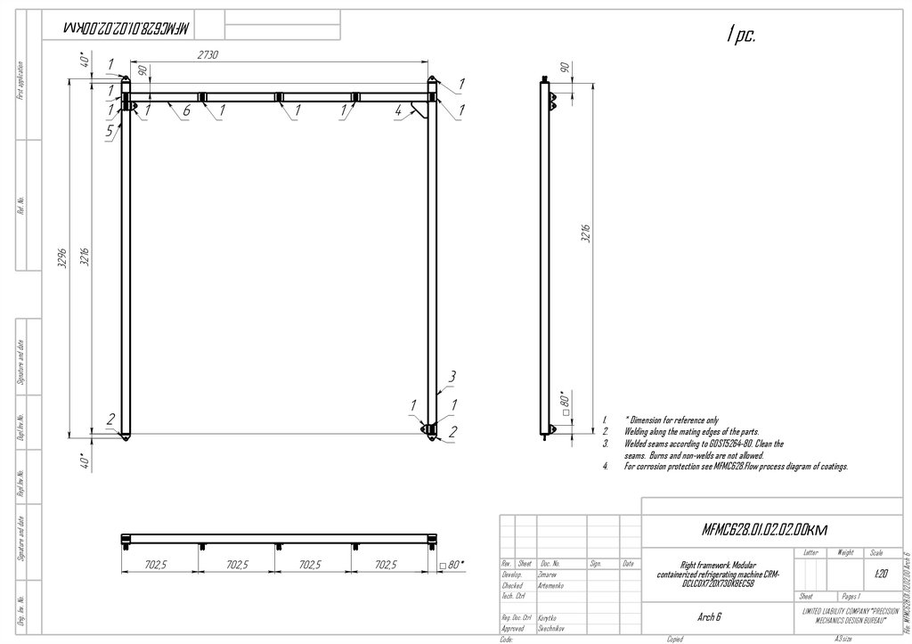
Right framework. Modular
containerized refrigerating machine CRMDCLCDX72DX73DK8EC58
Arch 6
Svechnikov
Copied
Scale
1:20
Sheet
Reg. Doc. Ctrl Korytko
Approved
Code:
Weight
Pages 1
LIMITED LIABILITY COMPANY "PRECISION
MECHANICS DESIGN BUREAU"
A3 size
File: MFMC628.01.02.02.00 Arch 6
Orig. Inv. No.
Signature and date
Repl.Inv.No.
4.
* Dimension for reference only
Welding along the mating edges of the parts.
Welded seams according to GOST5264-80. Clean the
seams. Burns and non-welds are not allowed.
For corrosion protection see MFMC628.Flow process diagram of coatings.
12.
1 pc.Dupl.Inv.No.
Signature and date
Ref. No.
First application
MFMC628.01.02.03.00КМ
1.
2.
3.
MFMC628.01.02.03.00КМ
Letter
Rev. Sheet Doc. No.
Develop.
Zimarev
Checked
Artemenko
Tech. Ctrl
Sign.
Date
Right framework. Modular
containerized refrigerating machine CRMDCLCDX72DX73DK8EC58
Arch 7
Svechnikov
Copied
Scale
1:20
Sheet
Reg. Doc. Ctrl Korytko
Approved
Code:
Weight
Pages 1
LIMITED LIABILITY COMPANY "PRECISION
MECHANICS DESIGN BUREAU"
A3 size
File: MFMC628.01.02.03.00 Arch 7
Orig. Inv. No.
Signature and date
Repl.Inv.No.
4.
* Dimension for reference only
Welding along the mating edges of the parts.
Welded seams according to GOST5264-80. Clean the
seams. Burns and non-welds are not allowed.
For corrosion protection see MFMC628.Flow process diagram of coatings.
13.
1 pc.Dupl.Inv.No.
Signature and date
Ref. No.
First application
MFMC628.01.02.04.00КМ
1.
2.
3.
MFMC628.01.02.04.00КМ
Letter
Rev. Sheet Doc. No.
Develop.
Zimarev
Checked
Artemenko
Tech. Ctrl
Sign.
Date
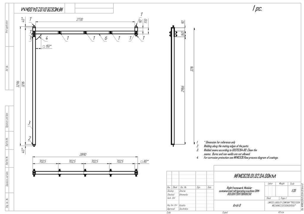
Right framework. Modular
containerized refrigerating machine CRMDCLCDX72DX73DK8EC58
Arch 8
Svechnikov
Copied
Scale
1:20
Sheet
Reg. Doc. Ctrl Korytko
Approved
Code:
Weight
Pages 1
LIMITED LIABILITY COMPANY "PRECISION
MECHANICS DESIGN BUREAU"
A3 size
File: MFMC628.01.02.04.00 Arch 8
Orig. Inv. No.
Signature and date
Repl.Inv.No.
4.
* Dimension for reference only
Welding along the mating edges of the parts.
Welded seams according to GOST5264-80. Clean the
seams. Burns and non-welds are not allowed.
For corrosion protection see MFMC628.Flow process diagram of coatings.
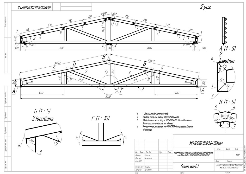
14.
2 pcs.First application
MFMC628.01.03.01.00КМ
A
2 locations
1.
2.
3.
4.
* Dimension for reference only
Welding along the mating edges of the parts.
Welded seams according to GOST5264-80. Clean the seams.
Burns and non-welds are not allowed.
For corrosion protection see MFMC628.Flow process diagram
of coatings
MFMC628.01.03.01.00КМ
Letter
Rev. Sheet Doc. No.
Develop.
Zimarev
Checked
Artemenko
Tech. Ctrl
Reg. Doc. Ctrl Korytko
Approved
Code:
Svechnikov
Sign.
Date
Weight
Roof framing Modular containerized refrigerating
machine КХМ-DCLCDX72DX73DK8EC58
1:20
Sheet
Frame work 1
Copied
Scale
Pages 1
LIMITED LIABILITY COMPANY "PRECISION
MECHANICS DESIGN BUREAU"
A3 size
File: MFMC628.01.03.01.00 Frame work 1
Orig. Inv. No.
Signature and date
Repl.Inv.No.
Dupl.Inv.No.
Signature and date
Ref. No.
2
location
s
15.
1 pc.MFMC628.01.03.02.00
1.
2.
3.
2
locations
* Dimension for reference only
Welding along the mating edges of the parts.
Welded seams according to GOST5264-80. Clean the seams.
Burns and non-welds are not allowed.
For corrosion protection see MFMC628.Flow process
diagram of coatings
4.
MFMC628.01.03.02.00КМ
Letter
Rev. Sheet Doc. No.
Develop.
Zimarev
Checked
Artemenko
Tech. Ctrl
Reg. Doc. Ctrl Korytko
Approved
Code:
Svechnikov
Sign.
Date
Weight
Roof framing Modular containerized refrigerating
machine CRM-DCLCDX72DX73DK8EC58
1:20
Sheet
Frame work 2
Copied
Scale
Pages 1
LIMITED LIABILITY COMPANY "PRECISION
MECHANICS DESIGN BUREAU"
A3 size
File: MFMC628.01.03.02.00 Frame work 2
Orig. Inv. No.
Signature and date
Repl.Inv.No.
Dupl.Inv.No.
Signature and date
Ref. No.
First application
2 locations
16.
MFMC628.01.03.03.002 pcs.
Signature and date
Ref. No.
First application
2
locations
2 locations
4.
* Dimension for reference only
Welding along the mating edges of the parts.
Welded seams according to GOST5264-80. Clean the seams.
Burns and non-welds are not allowed.
For corrosion protection see MFMC628.Flow process diagram of
coatings
MFMC628.01.03.03.00КМ
Letter
Rev. Sheet Doc. No.
Zimarev
Develop.
Checked
Artemenko
Tech. Ctrl
Reg. Doc. Ctrl Korytko
Approved
Code:
Svechnikov
Sign.
Date
Weight
Roof framing Modular containerized refrigerating
machine КХМ-DCLCDX72DX73DK8EC58
1:20
Sheet
Frame work 3
Copied
Scale
Pages 1
LIMITED LIABILITY COMPANY "PRECISION
MECHANICS DESIGN BUREAU"
A3 size
File: MFMC628.01.03.03.00 Frame work 3
Orig. Inv. No.
Signature and date
Repl.Inv.No.
Dupl.Inv.No.
1.
2.
3.
17.
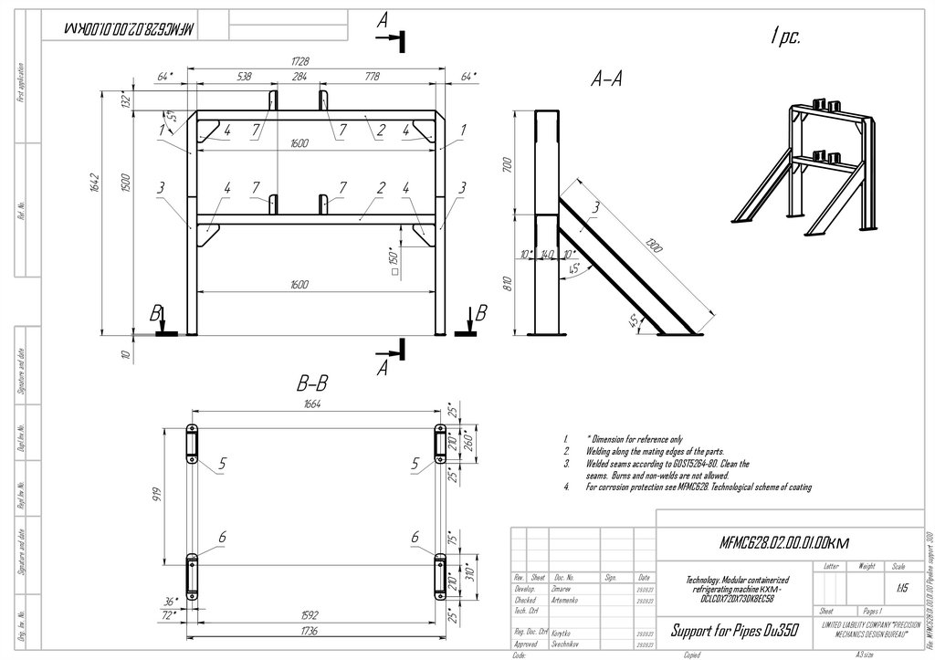
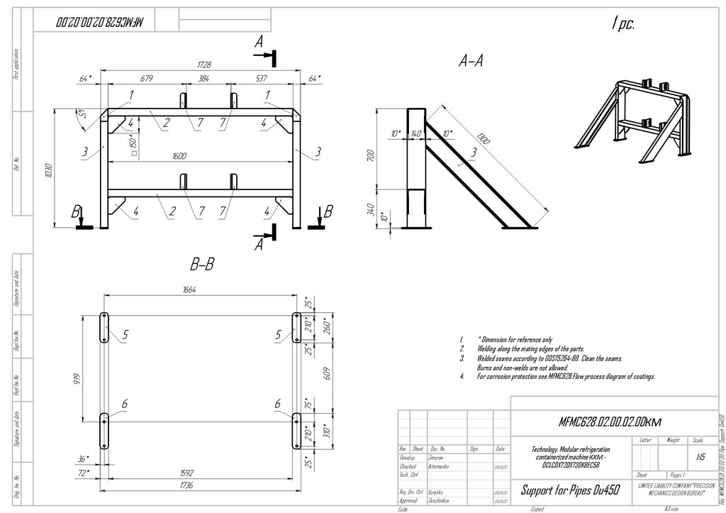
MFMC628.02.00.01.00КМ1.
2.
3.
Orig. Inv. No.
Signature and date
Repl.Inv.No.
4.
* Dimension for reference only
Welding along the mating edges of the parts.
Welded seams according to GOST5264-80. Clean the
seams. Burns and non-welds are not allowed.
For corrosion protection see MFMC628. Technological scheme of coating
MFMC628.02.00.01.00КМ
Letter
Rev. Sheet Doc. No.
Develop.
Zimarev
Checked
Artemenko
Tech. Ctrl
Reg. Doc. Ctrl Korytko
Approved
Code:
Svechnikov
Sign.
Date
29.09.23
29.09.23
Technology. Modular containerized
refrigerating machine КХМDCLCDX72DX73DK8EC58
Support for Pipes Du350
Pages 1
LIMITED LIABILITY COMPANY "PRECISION
MECHANICS DESIGN BUREAU"
29.09.23
Copied
Scale
1:15
Sheet
29.09.23
Weight
A3 size
File: MFMC628.01.00.01.00 Pipeline support 300
Dupl.Inv.No.
Signature and date
Ref. No.
First application
1 pc.
18.
1 pc.Orig. Inv. No.
Signature and date
Repl.Inv.No.
4.
* Dimension for reference only
Welding along the mating edges of the parts.
Welded seams according to GOST5264-80. Clean the seams.
Burns and non-welds are not allowed.
For corrosion protection see MFMC628.Flow process diagram of coatings.
MFMC628.02.00.02.00КМ
Letter
Rev. Sheet Doc. No.
Develop.
Zimarev
Checked
Artemenko
Tech. Ctrl
Sign.
Date
29.09.23
29.09.23
Approved
Code:
29.09.23
Svechnikov
Technology. Modular refrigeration
containerized machine КХМDCLCDX72DX73DK8EC58
Support for Pipes Du450
Copied
Scale
1:15
Sheet
Reg. Doc. Ctrl Korytko
Weight
Pages 1
LIMITED LIABILITY COMPANY "PRECISION
MECHANICS DESIGN BUREAU"
A3 size
File: MFMC628.01.00.02.00 Pipe Support Dn450
Dupl.Inv.No.
Signature and date
Ref. No.
First application
MFMC628.02.00.02.00
1.
2.
3.
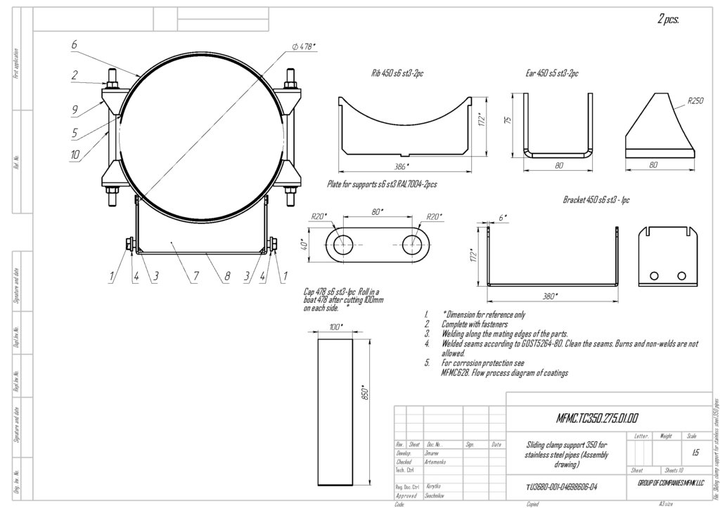
19.
Rib 450 s6 st3-2pcEar 450 s5 st3-2pc
Ref. No.
First application
2 pcs.
Plate for supports s6 st3 RAL7004-2pcs
1.
2.
3.
4.
Orig. Inv. No.
Signature and date
Repl.Inv.No.
5.
* Dimension for reference only
Complete with fasteners
Welding along the mating edges of the parts.
Welded seams according to GOST5264-80. Clean the seams. Burns and non-welds are not
allowed.
For corrosion protection see
MFMC628. Flow process diagram of coatings
MFMC.TC350.275.01.00
Rev. Sheet Doc. No. .
Develop.
Zimarev
Checked
Artemenko
Tech. Ctrl
Reg. Doc. Ctrl
Korytko
Approved
Code:
Svechnikov
Sign.
Date
Sliding clamp support 350 for
stainless steel pipes (Assembly
drawing)
ТU3680-001-04698606-04
Copied
Letter.
Weight
Scale
1:5
Sheet
Sheets 10
GROUP OF COMPANIES MFMK LLC
A3 size
File: Sliding clamp support for stainless steel.350 pipes
Cap 478 s6 st3-1pc Roll in a
boat 478 after cutting 100mm
on each side. *
Dupl.Inv.No.
Signature and date
Bracket 450 s6 st3 - 1pc
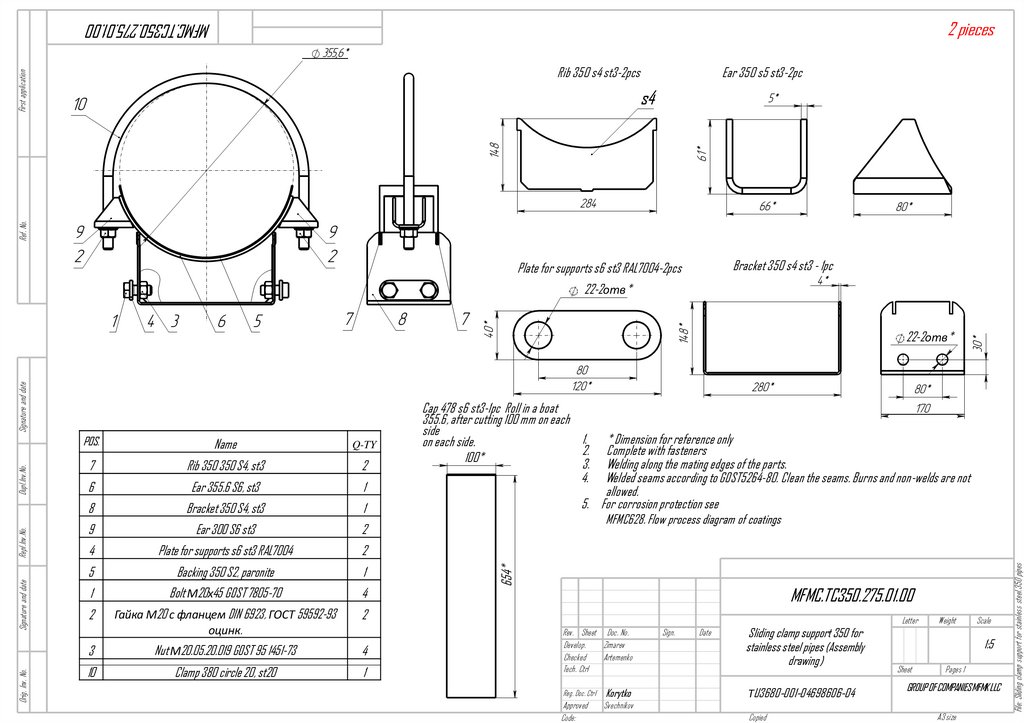
20.
2 piecesMFMC.TC350.275.01.00
First application
Rib 350 s4 st3-2pcs
Ear 350 s5 st3-2pc
Ref. No.
s4
Bracket 350 s4 st3 - 1pc
Plate for supports s6 st3 RAL7004-2pcs
22-2отв*
Name
Q-TY
7
Rib 350 350 S4, st3
2
6
Ear 355.6 S6, st3
1
8
Bracket 350 S4, st3
1
9
Ear 300 S6 st3
2
4
Plate for supports s6 st3 RAL7004
2
5
Backing 350 S2, paronite
1
1
Bolt М20х45 GOST 7805-70
4
2
Гайка М20 с фланцем DIN 6923, ГОСТ 59592-93
оцинк.
2
3
Nut М20.05.20.019 GOST 95 1451-73
4
10
Clamp 380 circle 20, st20
1
* Dimension for reference only
Complete with fasteners
Welding along the mating edges of the parts.
Welded seams according to GOST5264-80. Clean the seams. Burns and non-welds are not
allowed.
5. For corrosion protection see
MFMC628. Flow process diagram of coatings
654*
POS.
Cap 478 s6 st3-1pc Roll in a boat
355.6, after cutting 100 mm on each
side
1.
on each side.
2.
100*
3.
4.
MFMC.TC350.275.01.00
Rev. Sheet Doc. No.
Develop.
Zimarev
Checked
Artemenko
Tech. Ctrl
Reg. Doc. Ctrl
Korytko
Approved
Code:
Svechnikov
Sign.
Date
Sliding clamp support 350 for
stainless steel pipes (Assembly
drawing)
ТU3680-001-04698606-04
Copied
Letter
Weight
Scale
1:5
Sheet
Pages 1
GROUP OF COMPANIES MFMK LLC
A3 size
File: Sliding clamp support for stainless steel.350 pipes
Orig. Inv. No.
Signature and date
Repl.Inv.No.
Dupl.Inv.No.
Signature and date
22-2отв*
21.
MFMC628.03.01.00.00СБSignature and date
Ref. No.
First application
2 locations
Dupl.Inv.No.
1.
2.
MFMC628.03.01.00.00СБ
Rev. Sheet Doc. No.
Develop.
Zimarev
Checked
Artemenko
Tech. Ctrl
Sign.
Date
11,194
11,194
Reg. Doc. Ctrl Korytko
11,194
Approved
Code:
11,194
Svechnikov
Draining. Modular containerized refrigerating
machine
CRM-DCLCDX72DX73DK8EC58
Assembly drawing
Drainage system
Copied
Letter
Weight
Scale
1:25
Sheet
Pages 1
LIMITED LIABILITY COMPANY "PRECISION
MECHANICS DESIGN BUREAU"
A3 size
File: MFMC628.02.03.00.00)
Orig. Inv. No.
Signature and date
Repl.Inv.No.
3.
* Dimension for reference only
**Transitions 100-150 can be trimmed after mounting on the frame with
horizontal alignment.
Piping color: dark green RAL6026
22.
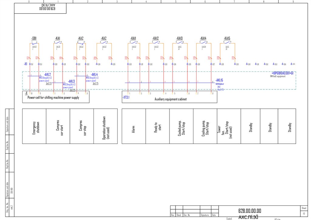
Name of the equipmentCompressor
KKS codes of technological equipment for drawing 628.00.00.00 TX KKS codes of technological equipment for drawing 628.00.00.00 TX
KKS
KKS
KKS
KKS
KKS
Е.I. Q-ty
МХМ 10PGB10AC001
МХМ 10PGB10AC002 МХМ 10PGB10AC003 МХМ 10PGB10AC004 МХМ 20PGB10AC001
pc.
1
10PGB10AH001KN01
10PGB10AH002KN01
10PGB10AH003KN01
10PGB10AH004KN01
20PGB10AH001KN01
KKS
МХМ 20PGB10AC002
20PGB10AH002KN01
KKS
МХМ 20PGB10AC003
20PGB10AH003KN01
KKS
МХМ 20PGB10AC004
20PGB10AH004KN01
Regulating input guide device (performance regulator)
pc.
1
10PGB10AH001‐Y11
10PGB10AH002‐Y11
10PGB10AH003‐Y11
10PGB10AH004‐Y11
20PGB10AH001‐Y11
20PGB10AH002‐Y11
20PGB10AH003‐Y11
20PGB10AH004‐Y11
Solenoid valve
Tubular heating element for oil heating
Oil pump
Ejector
Ejector
Oil cooler
Oil filter
Gas filter
Gas filter
Drying filter
Drying filter
Viewing glass with humidity indicator
Viewing glass with humidity indicator
Viewing glass with humidity indicator
Viewing glass with humidity indicator
Shut-of angle valve
Shut-of angle valve
Shut-of angle valve
Shut-of angle valve
Shut-off direct-flow valve for oil filling
Globe angle valve
Globe angle valve
Globe angle valve
Globe angle valve
Globe angle valve
Globe angle valve
Globe angle valve
Globe angle valve
Globe angle valve
Globe angle valve
Globe angle valve
Globe angle valve
Globe angle valve
Flow restricting orifice
Heat recovery unit - condenser ‐
Heat recovery unit - vaporiser exchanger ‐
Heat recovery unit - condenser ‐
Intermediate vessel of the feed-water economizer
Safety valve (condenser)
Safety valve (condenser)
Two-way valve (condenser)
Safety valve (condenser)
Safety valve (condenser)
Two-way valve (condenser)
DN450 butterfly valve (coolant inlet)
DN350 butterfly valve (coolant outlet)
DN350 butterfly valve (coolant inlet)
DN350 butterfly valve (coolant outlet)
Ball valve (condenser air outlet)
Ball valve (condenser drainage)
Ball valve (evaporator air outlet)
Ball valve (evaporator drainage)
pc.
pc.
pc.
pc.
pc.
pc.
pc.
pc.
pc.
pc.
pc.
pc.
pc.
pc.
pc.
pc.
pc.
pc.
pc.
pc.
pc.
pc.
pc.
pc.
pc.
pc.
pc.
pc.
pc.
pc.
pc.
pc.
pc.
pc.
pc.
pc.
pc.
pc.
pc.
pc.
pc.
pc.
pc.
pc.
pc.
pc.
pc.
pc.
pc.
pc.
pc.
pc.
1
1
1
1
1
1
1
1
1
1
1
1
1
1
1
1
1
1
1
1
1
1
1
1
1
1
1
1
1
1
1
1
1
1
1
1
1
1
1
1
1
1
1
1
1
1
1
1
1
1
1
1
10PGB10AH001‐Y12
10PGB10AH001‐E11
10PGB10AH001KP11
10PGB10AH001KP12
10PGB10AH001KP13
10PGB10AH001KC11
10PGB10AH001KT11
10PGB10AH001KT12
10PGB10AH001KT13
10PGB10AH001KT21
10PGB10AH001KT22
10PGB10AH001‐H11
10PGB10AH001‐H12
10PGB10AH001‐H13
10PGB10AH001‐H14
10PGB10AH001KA11
10PGB10AH001KA12
10PGB10AH001KA13
10PGB10AH001KA14
10PGB10AH001KA21
10PGB10AH001KA22
10PGB10AH001KA23
10PGB10AH001KA24
10PGB10AH001KA25
10PGB10AH001KA26
10PGB10AH001KA27
10PGB10AH001KA28
10PGB10AH001KA29
10PGB10AH001KA30
10PGB10AH001KA31
10PGB10AH001KA32
10PGB10AH001KA33
10PGB10AH001KA34
10PGB10AH001KA50
10PGB10AH001KC01
10PGB10AH001KC02
10PGB10AH001KC03
10PGB10AH001KD01
10PGB10AH001KA91
10PGB10AH001KA92
10PGB10AH001KA93
10PGB10AH001KA94
10PGB10AH001KA95
10PGB10AH001KA96
10PGB10AA011
10PGB10AA012
10PGB10AA013
10PGB10AA014
10PGB10AA414
10PGB10AA413
10PGB10AA412
10PGB10AA411
10PGB10AH002‐Y12
10PGB10AH002‐E11
10PGB10AH002KP11
10PGB10AH002KP12
10PGB10AH002KP13
10PGB10AH002KC11
10PGB10AH002KT11
10PGB10AH002KT12
10PGB10AH002KT13
10PGB10AH002KT21
10PGB10AH002KT22
10PGB10AH002‐H11
10PGB10AH002‐H12
10PGB10AH002‐H13
10PGB10AH002‐H14
10PGB10AH002KA11
10PGB10AH002KA12
10PGB10AH002KA13
10PGB10AH002KA14
10PGB10AH002KA21
10PGB10AH002KA22
10PGB10AH002KA23
10PGB10AH002KA24
10PGB10AH002KA25
10PGB10AH002KA26
10PGB10AH002KA27
10PGB10AH002KA28
10PGB10AH002KA29
10PGB10AH002KA30
10PGB10AH002KA31
10PGB10AH002KA32
10PGB10AH002KA33
10PGB10AH002KA34
10PGB10AH002KA50
10PGB10AH002KC01
10PGB10AH002KC02
10PGB10AH002KC03
10PGB10AH002KD01
10PGB10AH002KA91
10PGB10AH002KA92
10PGB10AH002KA93
10PGB10AH002KA94
10PGB10AH002KA95
10PGB10AH002KA96
10PGB10AA021
10PGB10AA022
10PGB10AA023
10PGB10AA024
10PGB10AA424
10PGB10AA423
10PGB10AA422
10PGB10AA421
10PGB10AH003‐Y12
10PGB10AH003‐E11
10PGB10AH003KP11
10PGB10AH003KP12
10PGB10AH003KP13
10PGB10AH003KC11
10PGB10AH003KT11
10PGB10AH003KT12
10PGB10AH003KT13
10PGB10AH003KT21
10PGB10AH003KT22
10PGB10AH003‐H11
10PGB10AH003‐H12
10PGB10AH003‐H13
10PGB10AH003‐H14
10PGB10AH003KA11
10PGB10AH003KA12
10PGB10AH003KA13
10PGB10AH003KA14
10PGB10AH003KA21
10PGB10AH003KA22
10PGB10AH003KA23
10PGB10AH003KA24
10PGB10AH003KA25
10PGB10AH003KA26
10PGB10AH003KA27
10PGB10AH003KA28
10PGB10AH003KA29
10PGB10AH003KA30
10PGB10AH003KA31
10PGB10AH003KA32
10PGB10AH003KA33
10PGB10AH003KA34
10PGB10AH003KA50
10PGB10AH003KC01
10PGB10AH003KC02
10PGB10AH003KC03
10PGB10AH003KD01
10PGB10AH003KA91
10PGB10AH003KA92
10PGB10AH003KA93
10PGB10AH003KA94
10PGB10AH003KA95
10PGB10AH003KA96
10PGB10AA031
10PGB10AA032
10PGB10AA033
10PGB10AA034
10PGB10AA434
10PGB10AA433
10PGB10AA432
10PGB10AA431
10PGB10AH004‐Y12
10PGB10AH004‐E11
10PGB10AH004KP11
10PGB10AH004KP12
10PGB10AH004KP13
10PGB10AH004KC11
10PGB10AH004KT11
10PGB10AH004KT12
10PGB10AH004KT13
10PGB10AH004KT21
10PGB10AH004KT22
10PGB10AH004‐H11
10PGB10AH004‐H12
10PGB10AH004‐H13
10PGB10AH004‐H14
10PGB10AH004KA11
10PGB10AH004KA12
10PGB10AH004KA13
10PGB10AH004KA14
10PGB10AH004KA21
10PGB10AH004KA22
10PGB10AH004KA23
10PGB10AH004KA24
10PGB10AH004KA25
10PGB10AH004KA26
10PGB10AH004KA27
10PGB10AH004KA28
10PGB10AH004KA29
10PGB10AH004KA30
10PGB10AH004KA31
10PGB10AH004KA32
10PGB10AH004KA33
10PGB10AH004KA34
10PGB10AH004KA50
10PGB10AH004KC01
10PGB10AH004KC02
10PGB10AH004KC03
10PGB10AH004KD01
10PGB10AH004KA91
10PGB10AH004KA92
10PGB10AH004KA93
10PGB10AH004KA94
10PGB10AH004KA95
10PGB10AH004KA96
10PGB10AA041
10PGB10AA042
10PGB10AA043
10PGB10AA044
10PGB10AA444
10PGB10AA443
10PGB10AA442
10PGB10AA441
20PGB10AH001‐Y12
20PGB10AH001‐E11
20PGB10AH001KP11
20PGB10AH001KP12
20PGB10AH001KP13
20PGB10AH001KC11
20PGB10AH001KT11
20PGB10AH001KT12
20PGB10AH001KT13
20PGB10AH001KT21
20PGB10AH001KT22
20PGB10AH001‐H11
20PGB10AH001‐H12
20PGB10AH001‐H13
20PGB10AH001‐H14
20PGB10AH001KA11
20PGB10AH001KA12
20PGB10AH001KA13
20PGB10AH001KA14
20PGB10AH001KA21
20PGB10AH001KA22
20PGB10AH001KA23
20PGB10AH001KA24
20PGB10AH001KA25
20PGB10AH001KA26
20PGB10AH001KA27
20PGB10AH001KA28
20PGB10AH001KA29
20PGB10AH001KA30
20PGB10AH001KA31
20PGB10AH001KA32
20PGB10AH001KA33
20PGB10AH001KA34
20PGB10AH001KA50
20PGB10AH001KC01
20PGB10AH001KC02
20PGB10AH001KC03
20PGB10AH001KD01
20PGB10AH001KA91
20PGB10AH001KA92
20PGB10AH001KA93
20PGB10AH001KA94
20PGB10AH001KA95
20PGB10AH001KA96
20PGB10AA011
20PGB10AA012
20PGB10AA013
20PGB10AA014
20PGB10AA414
20PGB10AA413
20PGB10AA412
20PGB10AA411
20PGB10AH002‐Y12
20PGB10AH002‐E11
20PGB10AH002KP11
20PGB10AH002KP12
20PGB10AH002KP13
20PGB10AH002KC11
20PGB10AH002KT11
20PGB10AH002KT12
20PGB10AH002KT13
20PGB10AH002KT21
20PGB10AH002KT22
20PGB10AH002‐H11
20PGB10AH002‐H12
20PGB10AH002‐H13
20PGB10AH002‐H14
20PGB10AH002KA11
20PGB10AH002KA12
20PGB10AH002KA13
20PGB10AH002KA14
20PGB10AH002KA21
20PGB10AH002KA22
20PGB10AH002KA23
20PGB10AH002KA24
20PGB10AH002KA25
20PGB10AH002KA26
20PGB10AH002KA27
20PGB10AH002KA28
20PGB10AH002KA29
20PGB10AH002KA30
20PGB10AH002KA31
20PGB10AH002KA32
20PGB10AH002KA33
20PGB10AH002KA34
20PGB10AH002KA50
20PGB10AH002KC01
20PGB10AH002KC02
20PGB10AH002KC03
20PGB10AH002KD01
20PGB10AH002KA91
20PGB10AH002KA92
20PGB10AH002KA93
20PGB10AH002KA94
20PGB10AH002KA95
20PGB10AH002KA96
20PGB10AA021
20PGB10AA022
20PGB10AA023
20PGB10AA024
20PGB10AA424
20PGB10AA423
20PGB10AA422
20PGB10AA421
20PGB10AH003‐Y12
20PGB10AH003‐E11
20PGB10AH003KP11
20PGB10AH003KP12
20PGB10AH003KP13
20PGB10AH003KC11
20PGB10AH003KT11
20PGB10AH003KT12
20PGB10AH003KT13
20PGB10AH003KT21
20PGB10AH003KT22
20PGB10AH003‐H11
20PGB10AH003‐H12
20PGB10AH003‐H13
20PGB10AH003‐H14
20PGB10AH003KA11
20PGB10AH003KA12
20PGB10AH003KA13
20PGB10AH003KA14
20PGB10AH003KA21
20PGB10AH003KA22
20PGB10AH003KA23
20PGB10AH003KA24
20PGB10AH003KA25
20PGB10AH003KA26
20PGB10AH003KA27
20PGB10AH003KA28
20PGB10AH003KA29
20PGB10AH003KA30
20PGB10AH003KA31
20PGB10AH003KA32
20PGB10AH003KA33
20PGB10AH003KA34
20PGB10AH003KA50
20PGB10AH003KC01
20PGB10AH003KC02
20PGB10AH003KC03
20PGB10AH003KD01
20PGB10AH003KA91
20PGB10AH003KA92
20PGB10AH003KA93
20PGB10AH003KA94
20PGB10AH003KA95
20PGB10AH003KA96
20PGB10AA031
20PGB10AA032
20PGB10AA033
20PGB10AA034
20PGB10AA434
20PGB10AA433
20PGB10AA432
20PGB10AA431
20PGB10AH004‐Y12
20PGB10AH004‐E11
20PGB10AH004KP11
20PGB10AH004KP12
20PGB10AH004KP13
20PGB10AH004KC11
20PGB10AH004KT11
20PGB10AH004KT12
20PGB10AH004KT13
20PGB10AH004KT21
20PGB10AH004KT22
20PGB10AH004‐H11
20PGB10AH004‐H12
20PGB10AH004‐H13
20PGB10AH004‐H14
20PGB10AH004KA11
20PGB10AH004KA12
20PGB10AH004KA13
20PGB10AH004KA14
20PGB10AH004KA21
20PGB10AH004KA22
20PGB10AH004KA23
20PGB10AH004KA24
20PGB10AH004KA25
20PGB10AH004KA26
20PGB10AH004KA27
20PGB10AH004KA28
20PGB10AH004KA29
20PGB10AH004KA30
20PGB10AH004KA31
20PGB10AH004KA32
20PGB10AH004KA33
20PGB10AH004KA34
20PGB10AH004KA50
20PGB10AH004KC01
20PGB10AH004KC02
20PGB10AH004KC03
20PGB10AH004KD01
20PGB10AH004KA91
20PGB10AH004KA92
20PGB10AH004KA93
20PGB10AH004KA94
20PGB10AH004KA95
20PGB10AH004KA96
20PGB10AA041
20PGB10AA042
20PGB10AA043
20PGB10AA044
20PGB10AA444
20PGB10AA443
20PGB10AA442
20PGB10AA441
23.
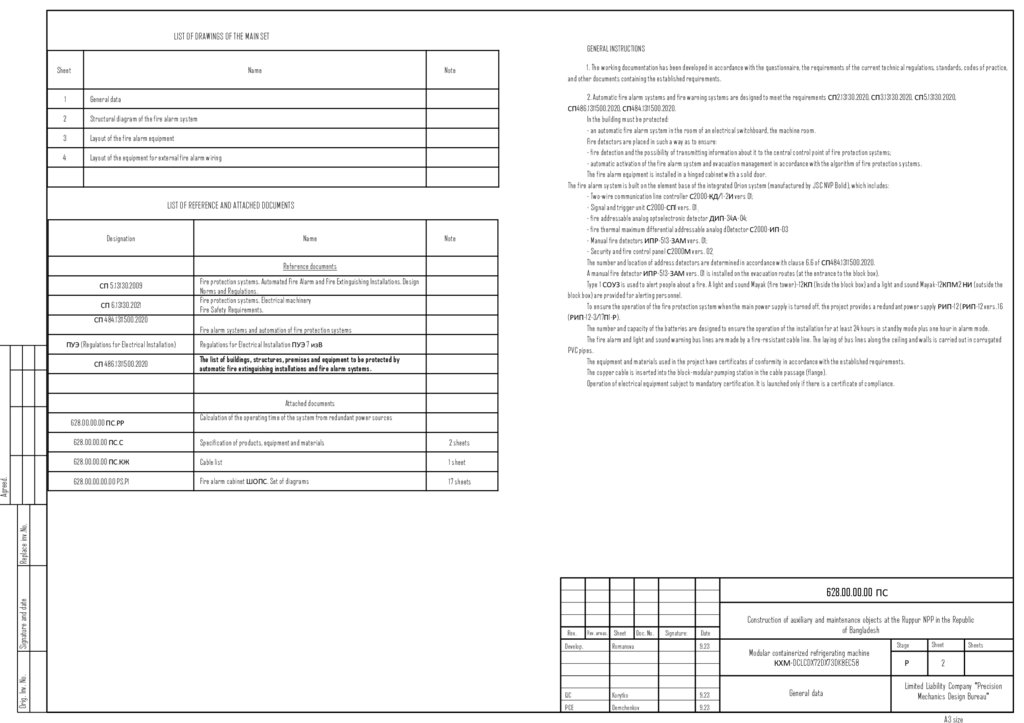
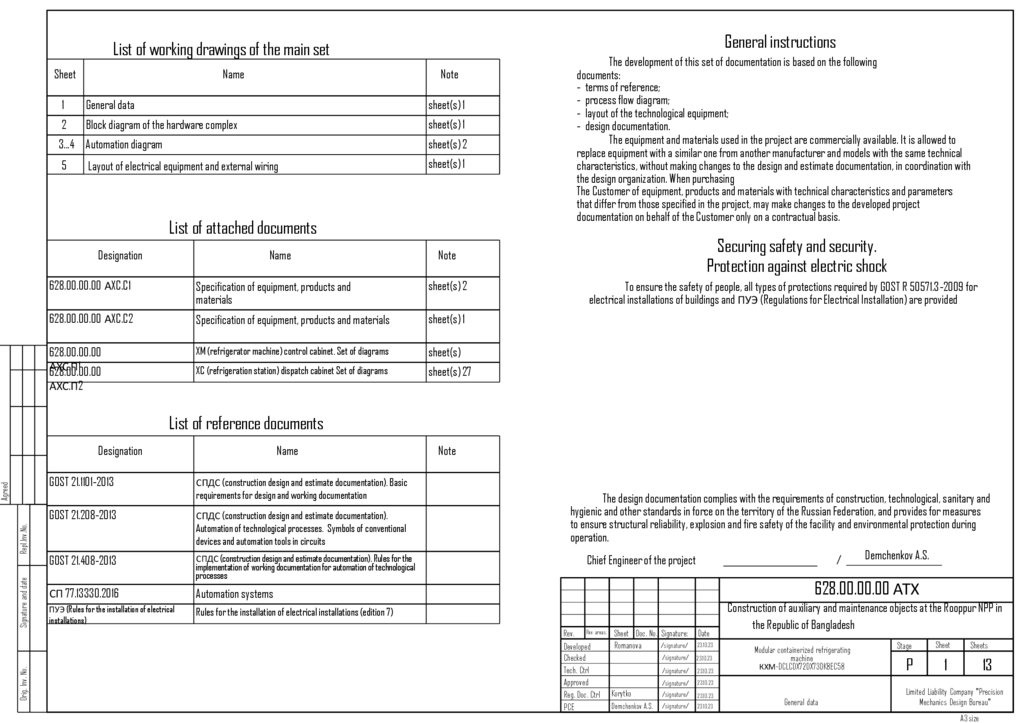
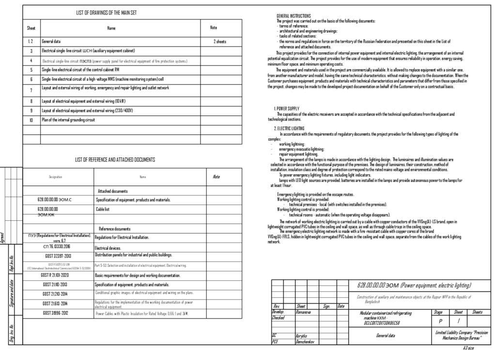
LIST OF DRAWINGS OF THE MAIN SETGENERAL INSTRUCTIONS
Sheet
Name
1
General data
2
Structural diagram of the fire alarm system
3
Layout of the fire alarm equipment
4
Layout of the equipment for external fire alarm wiring
Note
1. The working documentation has been developed in accordance with the questionnaire, the requirements of the current technical regulations, standards, codes of practice,
and other documents containing the established requirements.
Note
2. Automatic fire alarm systems and fire warning systems are designed to meet the requirements СП2.13130.2020, СП3.13130.2020, СП5.13130.2020,
СП486.1311500.2020, СП484.1311500.2020.
In the building must be protected:
- an automatic fire alarm system in the room of an electrical switchboard, the machine room.
Fire detectors are placed in such a way as to ensure:
- fire detection and the possibility of transmitting information about it to the central control point of fire protection systems;
- automatic activation of the fire alarm system and evacuation management in accordance with the algorithm of fire protection systems.
The fire alarm equipment is installed in a hinged cabinet with a solid door.
The fire alarm system is built on the element base of the integrated Orion system (manufactured by JSC NVP Bolid), which includes:
- Two-wire communication line controller С2000-КД/1-2И vers 01;
- Signal and trigger unit С2000-СП1 vers. 01 ;
- fire addressable analog optoelectronic detector ДИП-34А-04;
- fire thermal maximum differential addressable analog dDetector С2000-ИП-03
- Manual fire detectors ИПР-513-ЗАМ vers. 01;
- Security and fire control panel С2000М vers. 02 ;
The number and location of address detectors are determined in accordance with clause 6.6 of СП484.1311500.2020.
A manual fire detector ИПР-513-ЗАМ vers. 01 is installed on the evacuation routes (at the entrance to the block box).
Type 1 СОУЗ is used to alert people about a fire. A light and sound Mayak (fire tower)-12КП (Inside the block box) and a light and sound Mayak-12КПМ2 НИ (outside the
block box) are provided for alerting personnel.
To ensure the operation of the fire protection system when the main power supply is turned off, the project provides a redundant power supply РИП-12 (РИП-12 vers. 16
(РИП-12-3/17П1-Р).
The number and capacity of the batteries are designed to ensure the operation of the installation for at least 24 hours in standby mode plus one hour in alarm mode.
The fire alarm and light and sound warning bus lines are made by a fire-resistant cable line. The laying of bus lines along the ceiling and walls is carried out in corrugated
PVC pipes.
The equipment and materials used in the project have certificates of conformity in accordance with the established requirements.
The copper cable is inserted into the block-modular pumping station in the cable passage (flange).
Operation of electrical equipment subject to mandatory certification. It is launched only if there is a certificate of compliance.
LIST OF REFERENCE AND ATTACHED DOCUMENTS
Designation
Name
Reference documents
СП 5.13130.2009
СП 6.13130.2021
Fire protection systems. Automated Fire Alarm and Fire Extinguishing Installations. Design
Norms and Regulations.
Fire protection systems. Electrical machinery
Fire Safety Requirements.
СП 484.1311500.2020
Fire alarm systems and automation of fire protection systems
ПУЭ (Regulations for Electrical Installation)
СП 486.1311500.2020
Regulations for Electrical Installation ПУЭ 7 изВ
The list of buildings, structures, premises and equipment to be protected by
automatic fire extinguishing installations and fire alarm systems.
Attached documents
Calculation of the operating time of the system from redundant power sources
628.00.00.00 ПС.С
Specification of products, equipment and materials
2 sheets
628.00.00.00 ПС.КЖ
Cable list
1 sheet
628.00.00.00.00 PS.P1
Fire alarm cabinet ШОПС. Set of diagrams
17 sheets
Orig. Inv. No.
Signature and date
Replace inv.No.
Agreed.
628.00.00.00 ПС.РР
628.00.00.00 ПС
Rev.
Develop.
Rev. areas. Sheet
Doc. No.
Romanova
Signature:
Date
9.23
QC
Korytko
9.23
PCE
Demchenkov
9.23
Construction of auxiliary and maintenance objects at the Ruppur NPP in the Republic
of Bangladesh
Modular containerized refrigerating machine
КХМ-DCLCDX72DX73DK8EC58
General data
Stage
Sheet
Р
2
Sheets
Limited Liability Company "Precision
Mechanics Design Bureau"
A3 size
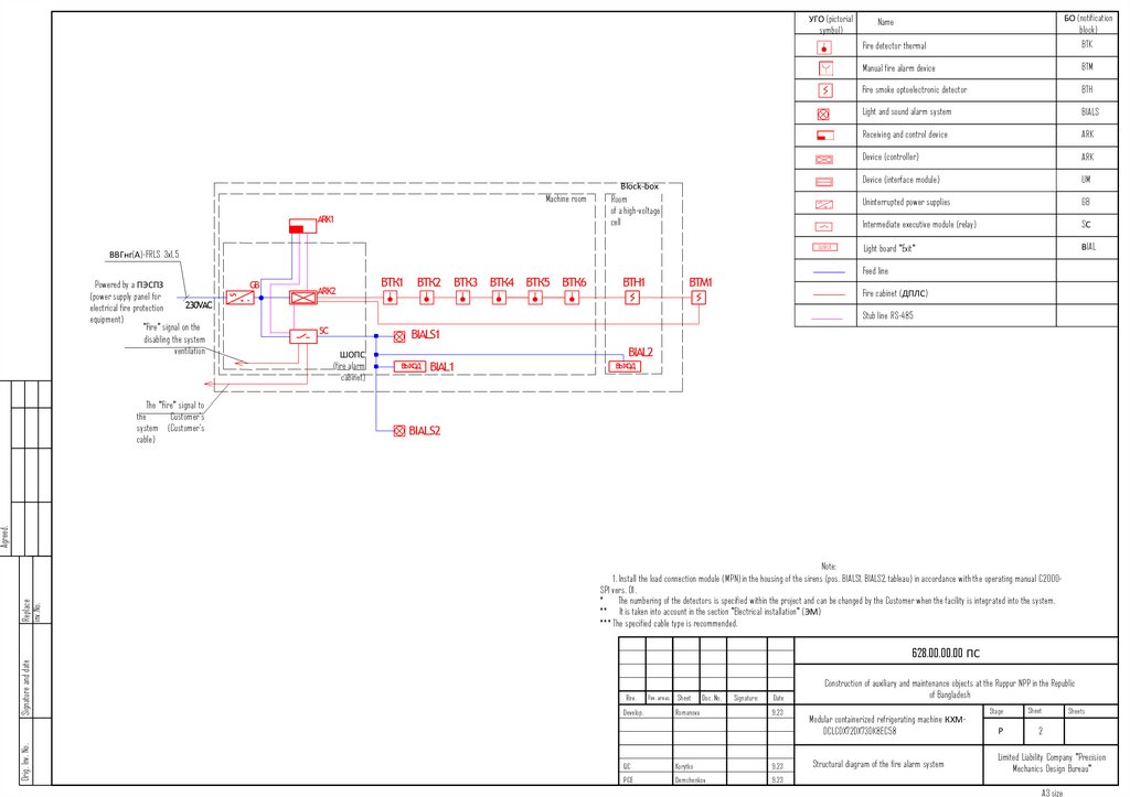
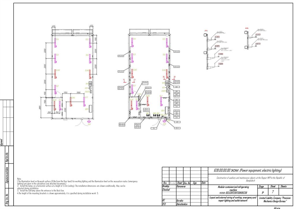
24.
УГО (pictorialsymbol)
Machine room
Block-box
Room
of a high-voltage
cell
OUTPUT
ВВГнг(А)-FRLS 3x1,5
БО (notification
block)
Name
Fire detector thermal
BTK
Manual fire alarm device
BTM
Fire smoke optoelectronic detector
BTH
Light and sound alarm system
BIALS
Receiving and control device
ARK
Device (controller)
ARK
Device (interface module)
UM
Uninterrupted power supplies
GB
Intermediate executive module (relay)
SС
Light board "Exit"
ВIAL
Feed line
Powered by a ПЭСПЗ
(power supply panel for
electrical fire protection
equipment)
"Fire" signal on the
disabling the system
ventilation
Fire cabinet (ДПЛС)
Stub line RS-485
ШОПС
(fire alarm
cabinet)
Orig. Inv. No.
Signature and date
Replace
inv.No.
Agreed.
The "Fire" signal to
the
Customer's
system (Customer's
cable)
Note:
1. Install the load connection module (MPN) in the housing of the sirens (pos. BIALS1, BIALS2, tableau) in accordance with the operating manual C2000SP1 vers. 01.
*
The numbering of the detectors is specified within the project and can be changed by the Customer when the facility is integrated into the system.
** It is taken into account in the section "Electrical installation" (ЭМ)
*** The specified cable type is recommended.
628.00.00.00 ПС
Rev.
Develop.
Rev. areas. Sheet
Doc. No.
Romanova
Signature:
Date
9.23
QC
Korytko
9.23
PCE
Demchenkov
9.23
Construction of auxiliary and maintenance objects at the Ruppur NPP in the Republic
of Bangladesh
Modular containerized refrigerating machine КХМDCLCDX72DX73DK8EC58
Structural diagram of the fire alarm system
Stage
Sheet
Р
2
Sheets
Limited Liability Company "Precision
Mechanics Design Bureau"
A3 size
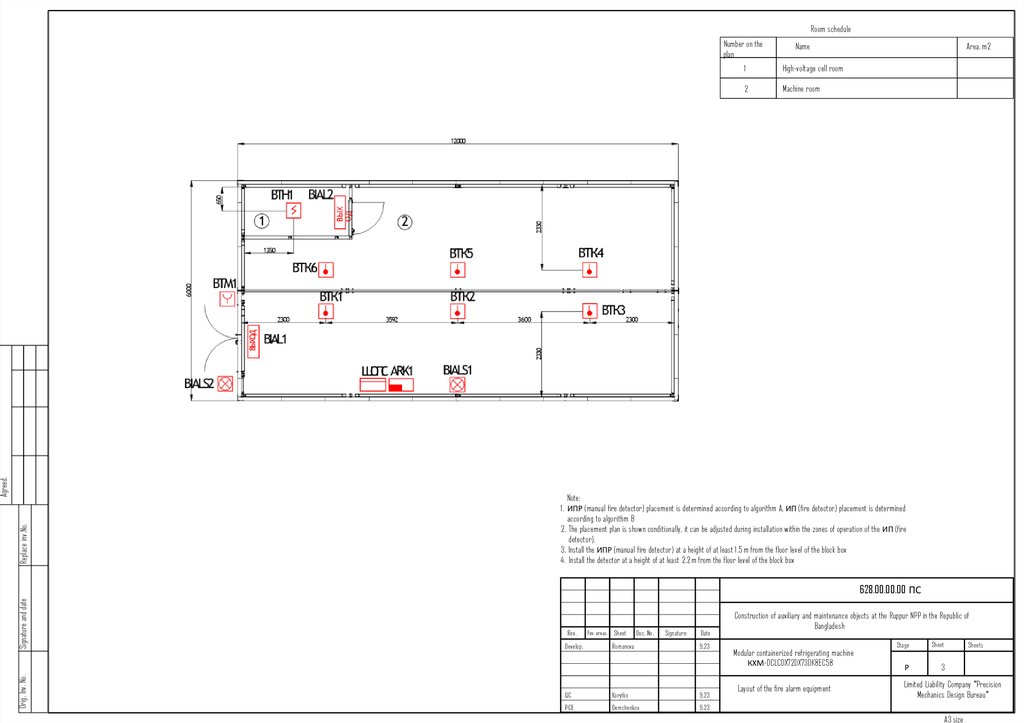
25.
Room scheduleReplace inv.No.
Agreed.
Number on the
plan
Name
1
High-voltage cell room
2
Machine room
Area, m2
Note:
1. ИПР (manual fire detector) placement is determined according to algorithm A, ИП (fire detector) placement is determined
according to algorithm B
2. The placement plan is shown conditionally, it can be adjusted during installation within the zones of operation of the ИП (fire
detector).
3. Install the ИПР (manual fire detector) at a height of at least 1.5 m from the floor level of the block box
4. Install the detector at a height of at least 2.2 m from the floor level of the block box
Orig. Inv. No.
Signature and date
628.00.00.00 ПС
Rev.
Develop.
Rev. areas. Sheet
Doc. No.
Romanova
Signature:
Date
9.23
QC
Korytko
9.23
PCE
Demchenkov
9.23
Construction of auxiliary and maintenance objects at the Ruppur NPP in the Republic of
Bangladesh
Modular containerized refrigerating machine
КХМ-DCLCDX72DX73DK8EC58
Layout of the fire alarm equipment
Stage
Sheet
Р
3
Sheets
Limited Liability Company "Precision
Mechanics Design Bureau"
A3 size
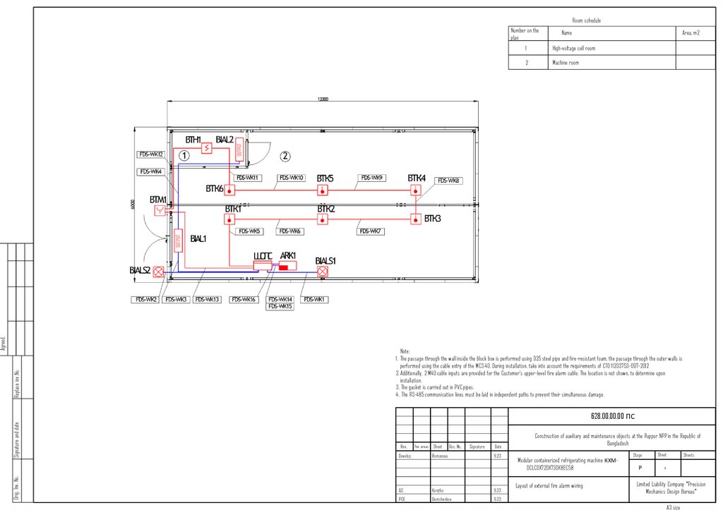
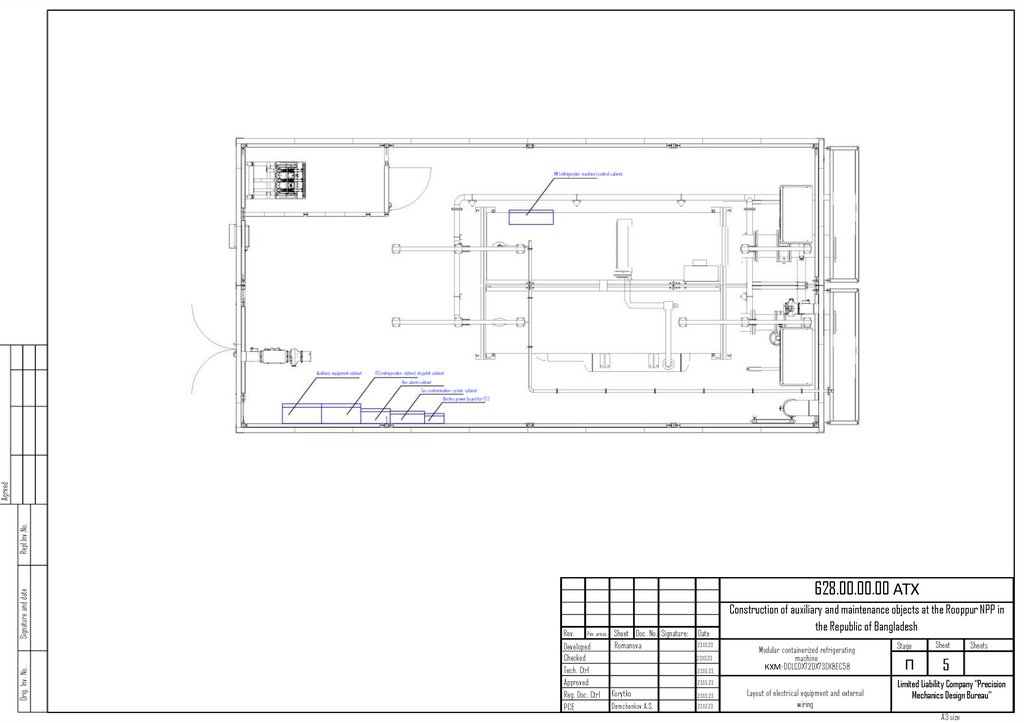
26.
Room scheduleNumber on the
plan
Name
Area, m2
High-voltage cell room
2
Machine room
Replace inv.No.
Agreed.
OUTPUT
OUTPUT
1
Note:
1. The passage through the wall inside the block box is performed using D25 steel pipe and fire-resistant foam, the passage through the outer walls is
performed using the cable entry of the MCS 40. During installation, take into account the requirements of CTO 11233753-007-2012
2. Additionally, 2 M40 cable inputs are provided for the Customer's upper-level fire alarm cable. The location is not shown, to determine upon
installation.
3. The gasket is carried out in PVC pipes.
4. The RS-485 communication lines must be laid in independent paths to prevent their simultaneous damage.
Orig. Inv. No.
Signature and date
628.00.00.00 ПС
Rev.
Develop.
Rev. areas. Sheet
Doc. No.
Romanova
Signature:
Date
9.23
QC
Korytko
9.23
PCE
Demchenkov
9.23
Construction of auxiliary and maintenance objects at the Ruppur NPP in the Republic of
Bangladesh
Modular containerized refrigerating machine КХМDCLCDX72DX73DK8EC58
Layout of external fire alarm wiring
Stage
Sheet
Р
4
Sheets
Limited Liability Company "Precision
Mechanics Design Bureau"
A3 size
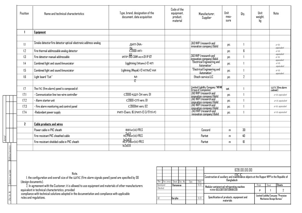
27.
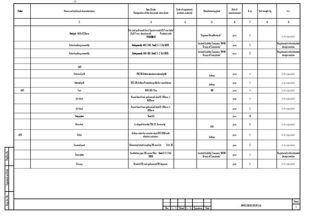
Position1
1.1
Name and technical characteristics
Smoke detector fire detector optical-electronic address-analog
Fire thermal addressable analog detector
1.3
Fire detector manual addressable
1.4
Combined light and sound Annunciator
Ligghtning (Маяк)-12-КП
1.5
Combined light and sound Annunciator
Lightning (Mayak)-12-КПМ2 НИ
1.6
Light board "Exit"
1.7
The ПС (fire alarm) panel is composed of:
1.7.1
- Communication line two-wire controller
1.7.2
- Alarm starter unit
С2000-СП1 vers. 01
1.7.3
- Fire alarm monitoring and control panel
С2000М vers. 02
1.7.4
-Redundant power supply
2
Cable products and wires
Additional inventory
Fire-resistant shielded cable in PVC sheath
Signature and date
ДИП-34А04
С2000-ИП03
ИПР-513-3AM исп.01 IP 67
1.2
Fire-resistant PVC sheathed cable
Orig. Inv. No.
Manufacturer,
Supplier
Unit
measure
Qty.
ZAO NVP (research and
innovation company) Bolid
pc.
1
pc.
6
ZAO NVP (research and
innovation company) Bolid
"Electrical Engineering and
Automation"
"Electrical Engineering and
Automation"
Eltech-service LLC
pc.
1
pc.
1
pc.
1
pc.
2
Limited Liability Company "MFMK
Group of Companies"
set.
1
ZAO NVP (research and
innovation company) Bolid
ZAO NVP (research and
innovation company) Bolid
ZAO NVP (research and
innovation company) Bolid
ZAO NVP (research and
innovation company) Bolid
ШПС (fire alarm
cabinet)
pc.
1
or its equivalent
pc.
1
or its equivalent
pc.
1
or its equivalent
pc.
1
or its equivalent
Concord
m
30
Paritet
m
40
Paritet
m
10
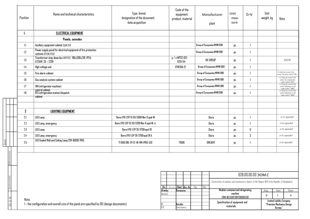
Unit
weight,
kg
Note
Equipment
Power cable in PVC sheath
Agreed
Code of the
equipment,
product,
material
Type, brand, designation of the
document, data acquisition
М12
С2000-КДЛ-2И vers. 01
РИП-12vers. 16 (РИП-12-3/17П1-Р)
ВВГнг(А)-FRLS
3х1.5
КСРВнг(А)-FRLS
1х2х0.8
КСРЭВнг(А)-FRLS
1х2х0.8
Note.
1. the configuration and overall size of the ШПС (Fire alarm signals panel) panel are specified by DD
(design documents).
2. In agreement with the Customer, it is allowed to use equipment and materials of other manufacturers
equivalent in technical characteristics, provided
compliance with technical solutions adopted in the documentation and compliance with applicable
rules and regulations.
or its
equivalent
or its
equivalent
or its
equivalent
or its
equivalent
or its
equivalent
628.00.00.00
ПС.С
Construction of auxiliary and maintenance objects at the Ruppur NPP in the Republic of
Rev. Rev. areas. Sheet Doc. No.
Developed
Romanova
Checked
QC
Korytko
Sign.
Date
9.23
9.23
Bangladesh
Modular containerized refrigerating machine
КХМ-DCLCDX72DX73DK8EC58
Specification of products, equipment and
materials
Stage
Sheet
Sheets
Р
1
2
Limited Liability Company "Precision
Mechanics Design Bureau"
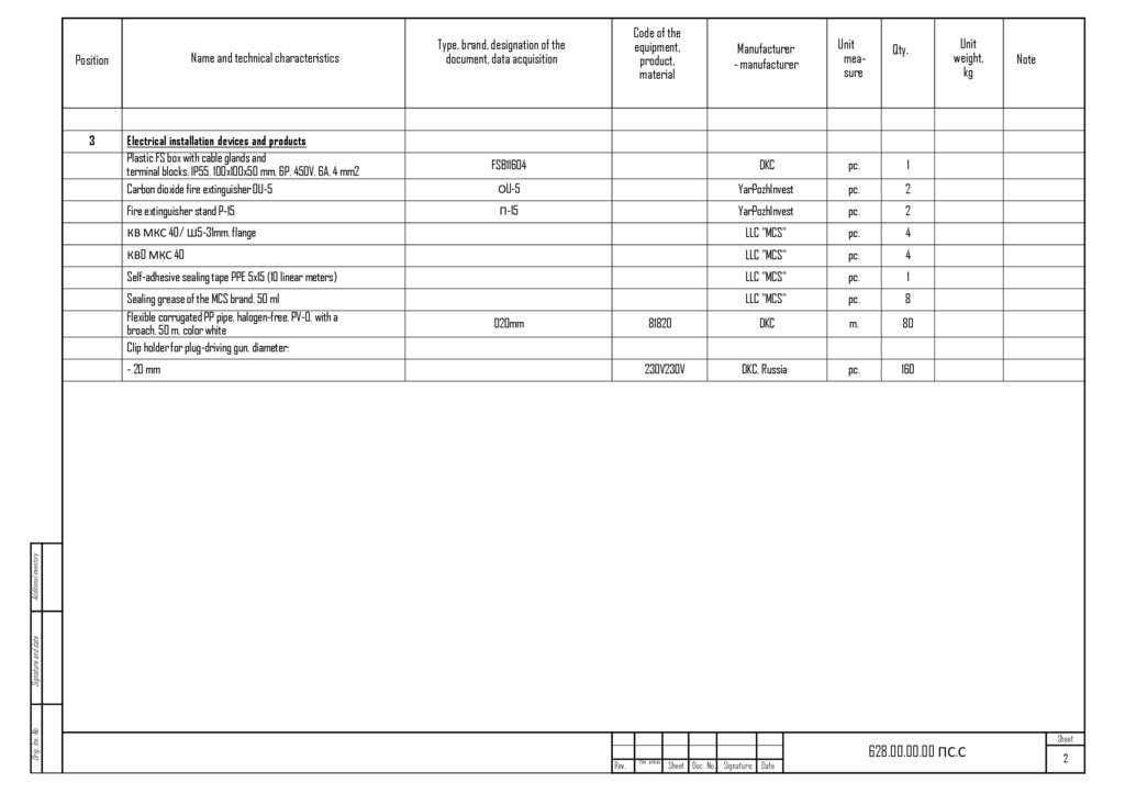
28.
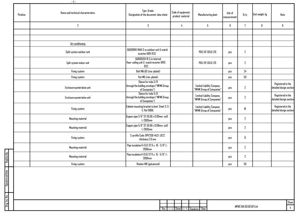
Name and technical characteristicsPosition
3
Code of the
equipment,
product,
material
Type, brand, designation of the
document, data acquisition
Manufacturer
- manufacturer
Unit
measure
Qty.
Electrical installation devices and products
Plastic FS box with cable glands and
terminal blocks, IP55, 100x100x50 mm, 6P, 450V, 6A, 4 mm2
Carbon dioxide fire extinguisher OU-5
FSB11604
DKC
pc.
1
ОU-5
YarPozhInvest
pc.
2
Fire extinguisher stand P-15
П-15
YarPozhInvest
pc.
2
КВ МКС 40/ Ш5-31mm, flange
LLC "MCS"
pc.
4
КВO МКС 40
LLC "MCS"
pc.
4
Self-adhesive sealing tape PPE 5x15 (10 linear meters)
LLC "MCS"
pc.
1
Sealing grease of the MCS brand, 50 ml
Flexible corrugated PP pipe, halogen-free, PV-0, with a
broach, 50 m, color white
Clip holder for plug-driving gun, diameter:
LLC "MCS"
pc.
8
81820
DKC
m.
80
230V230V
DKC, Russia
pc.
160
D20mm
Note
Orig. Inv. No.
Signature and date
Additional inventory
- 20 mm
Unit
weight,
kg
Rev.
Rev. areas.
Sheet Doc. No. Signature: Date
628.00.00.00 ПС.С
Sheet
2
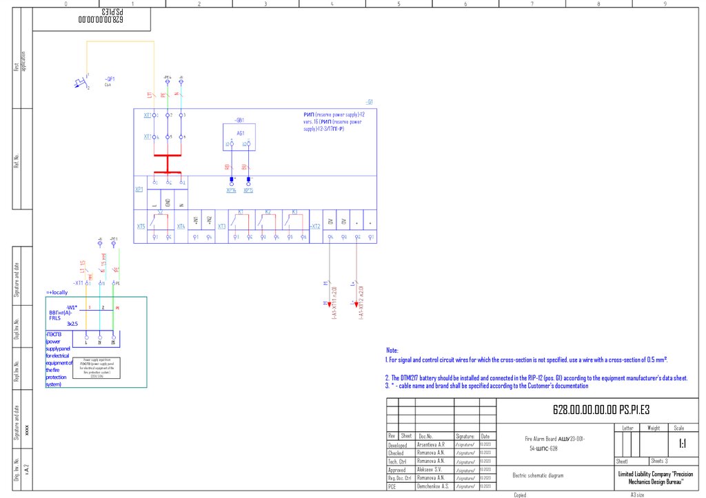
29.
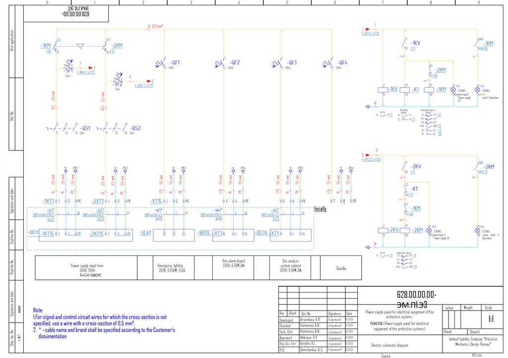
Firstapplication
628.00.00.00.00
PS.P1.E3
Signature and date
Ref. No.
РИП (reserve power supply)-12
vers. 16 (РИП (reserve power
supply)-12-3/17П1-Р)
=+locally
Dupl.Inv.No.
-W1*
ВВГнг(А)FRLS
3x2.5
L
2
N
PE
PE
Power supply input from
ПЭСПЗ (power supply panel
for electrical equipment of the
fire protection system)
220V, 50Hz
Note:
1. For signal and control circuit wires for which the cross-section is not specified, use a wire with a cross-section of 0.5 mm².
2. The DTM1217 battery should be installed and connected in the RIP-12 (pos. G1) according to the equipment manufacturer's data sheet.
3. * - cable name and brand shall be specified according to the Customer's documentation
хххх
628.00.00.00.00 PS.P1.E3
v.А.2
Orig. Inv. No.
Signature and date
Repl.Inv.No.
-ПЭСПЗ
(power
supplypanel
for electrical
equipmentof
the fire
protection
system)
1
Letter
Rev Sheet Doc.No.
.
Arsentieva A.R
Developed
Romanova
A.N.
Checked
Romanova A.N.
Tech. Ctrl
Alekseev S.V.
Approved
Reg. Doc. Ctrl Romanova A.N.
Demchenkov A.S.
PCE
Signature:
Date
/signature/
10.2023
/signature/
10.2023
/signature/
10.2023
/signature/
10.2023
/signature/
10.2023
/signature/
10.2023
Weight
Fire Alarm Board АШУ23-001-
1:1
54-ШПС-628
Sheets 3
Sheet1
Electric schematic diagram
Copied
Scale
Limited Liability Company "Precision
Mechanics Design Bureau"
A3 size
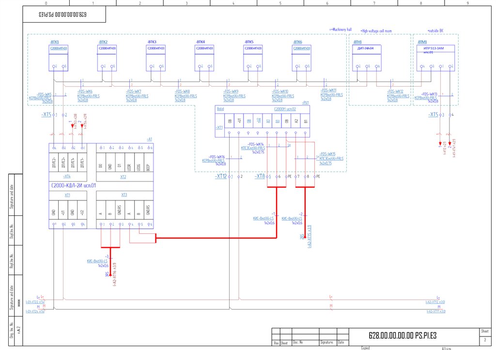
30.
628.00.00.00.00 PS.P1.E3+High-voltage cell room
+outside BK
хххх
v.А.2
Orig. Inv. No.
Signature and date
Repl.Inv.No.
Dupl.Inv.No.
Signature and date
=+Machinery hall
Rev. Sheet
Doc. No
Signature:
Date
Sheet
628.00.00.00.00 PS.P1.E3
Copied
2
A3 size
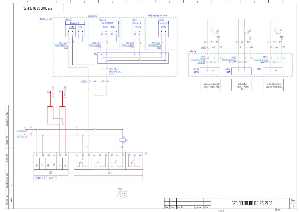
31.
628.00.00.00.00 PS.P1.E3+High-voltage cell room
outside BK
+Machinery hall
Mayak-12-KP
Mayak-12-KPM2 NI
SOUND
LIGHT
SOUND
+ -
+ -
+ -
Lightning-12
Lightning-12
LIGHT
OUTPUT
OUTPUT
+ -
+ -
+ -
=+locally
-AuxCab
(ШСН)
-AutCab
(ША)
Automation
cabinet. Alarm:
FIRE
To the Customer's
system. Alarm FIRE
хххх
v.А.2
Orig. Inv. No.
Signature and date
Repl.Inv.No.
Dupl.Inv.No.
Signature and date
Auxiliary equipment
cabinet Alarm: FIRE
-ShPA
Rev. Sheet
Doc. No
Signature:
Sheet
628.00.00.00.00 PS.P1.E3
Date
Copied
3
A3 size
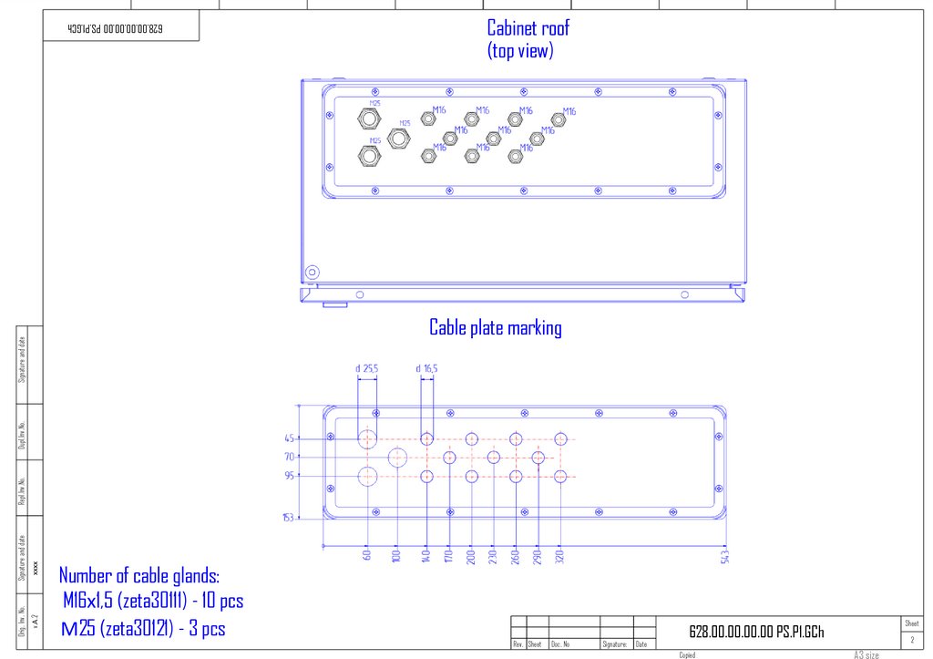
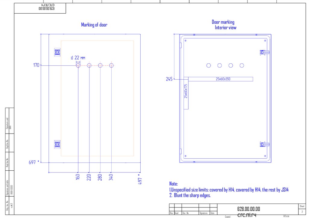
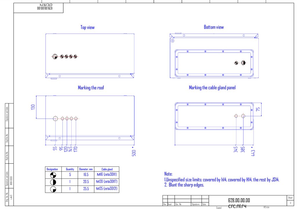
32.
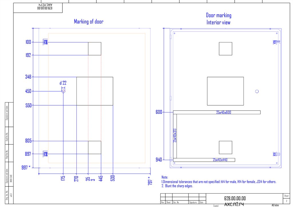
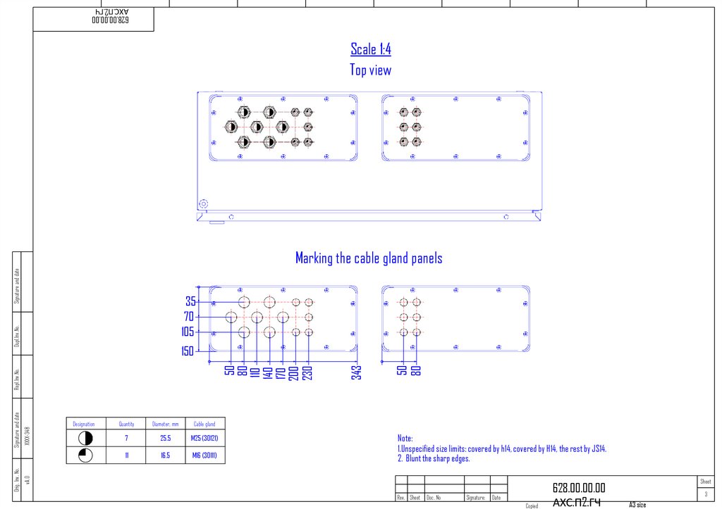
Cabinet roof(top view)
628.00.00.00.00 PS.P1.GCh
хххх
v.А.2
Orig. Inv. No.
Signature and date
Repl.Inv.No.
Dupl.Inv.No.
Signature and date
Cable plate marking
Number of cable glands:
M16х1,5 (zeta30111) - 10 pcs
М25 (zeta30121) - 3 pcs
Rev. Sheet
Doc. No
Signature:
Date
Sheet
628.00.00.00.00 PS.P1.GCh
Copied
2
A3 size
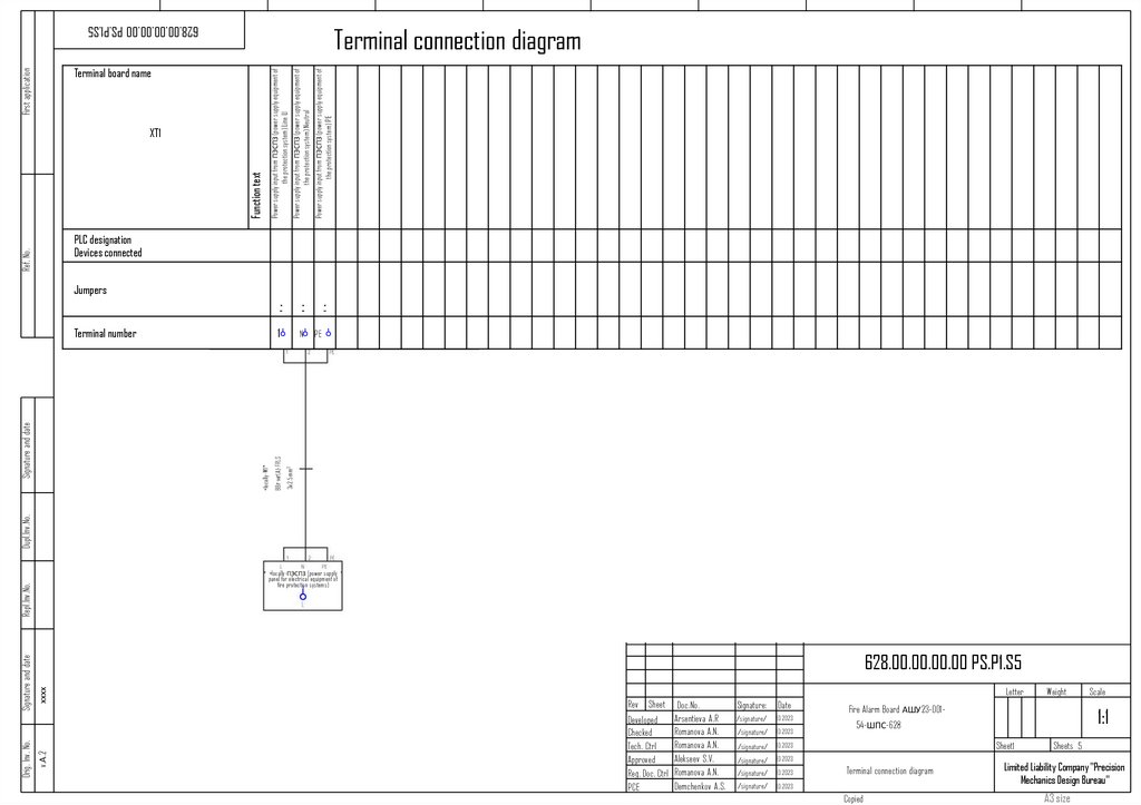
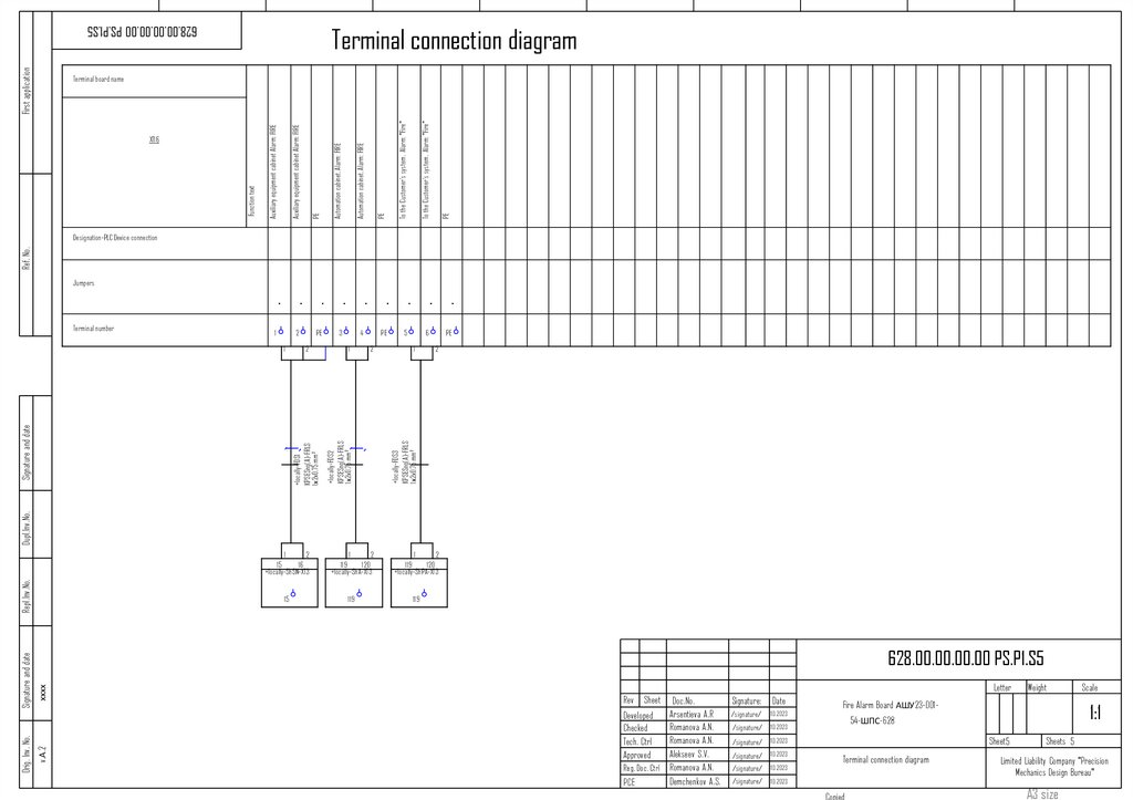
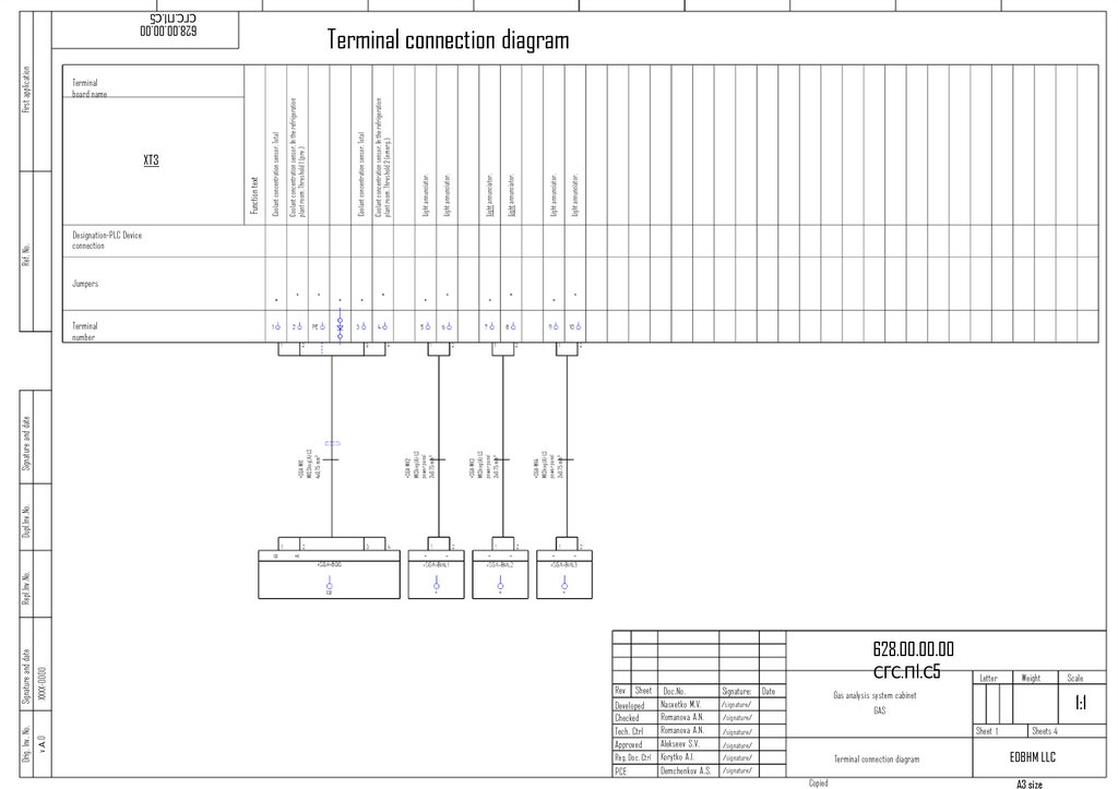
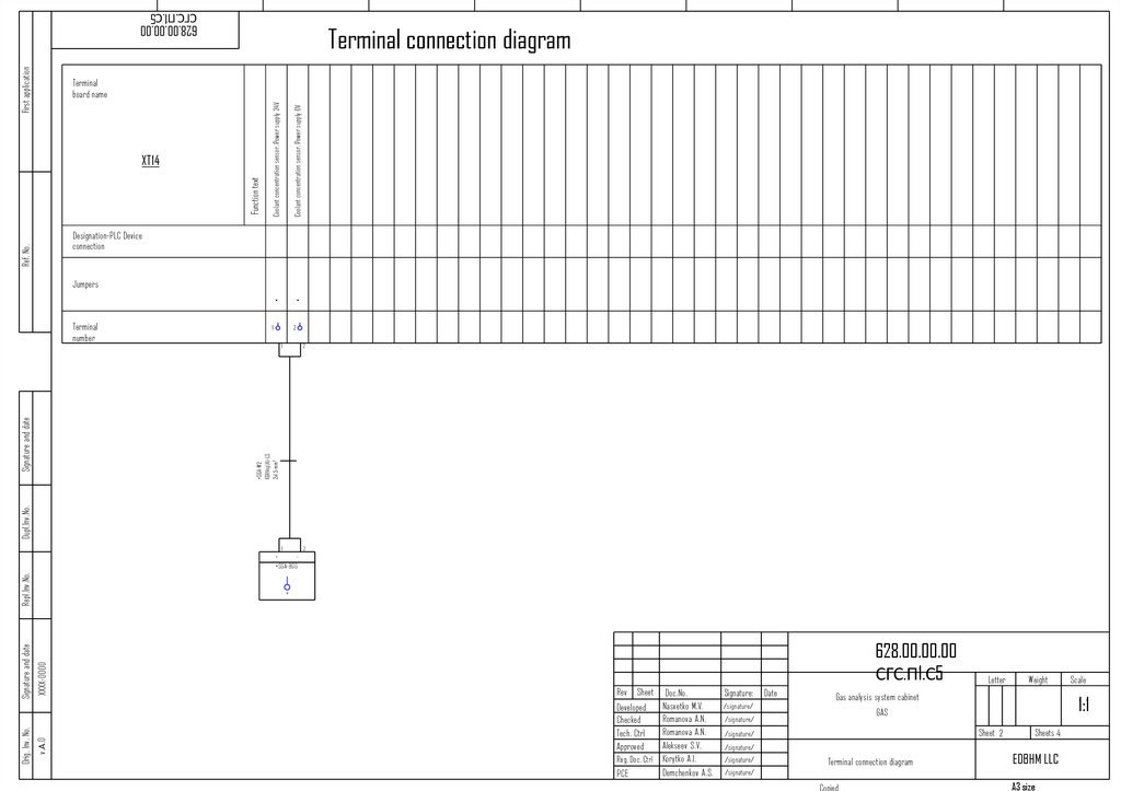
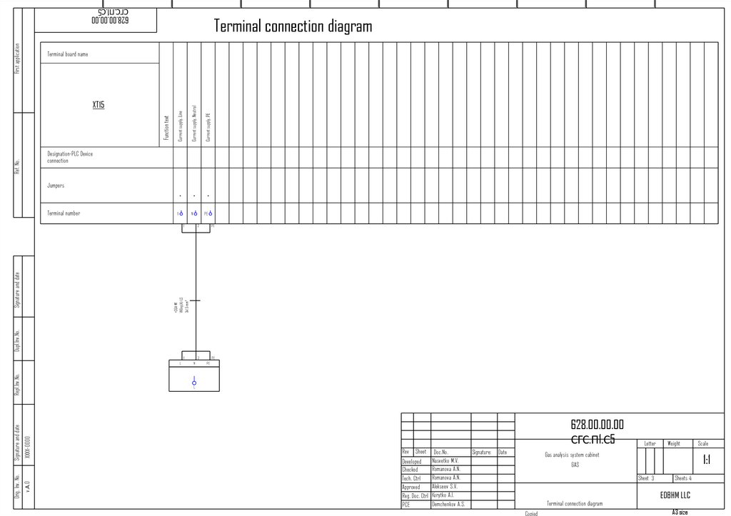
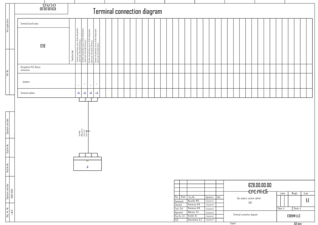
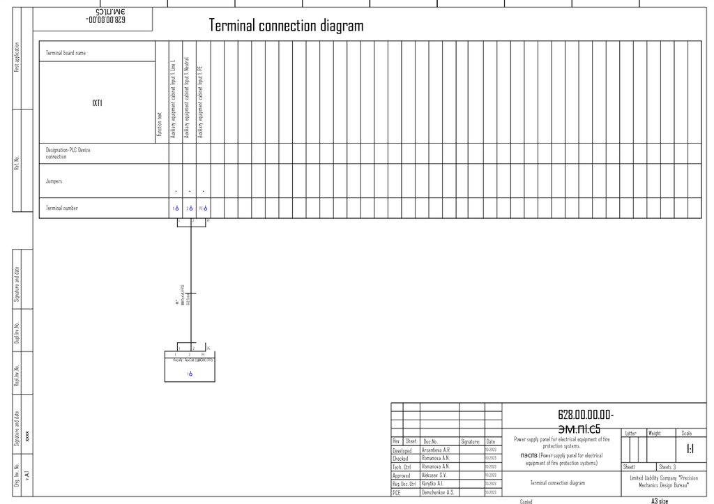
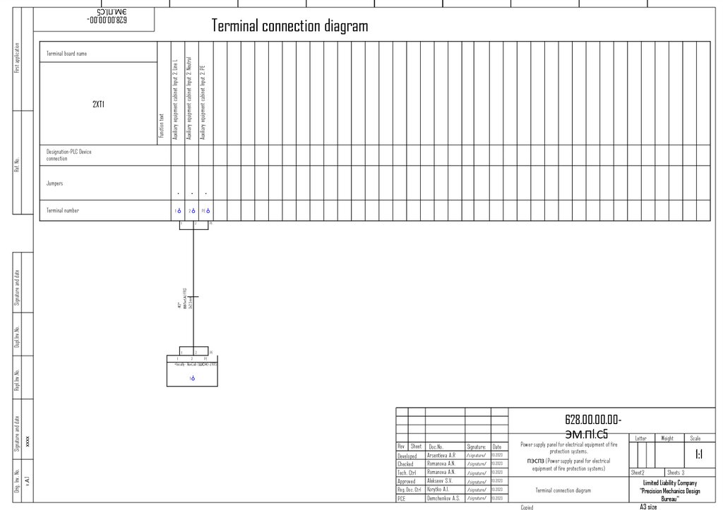
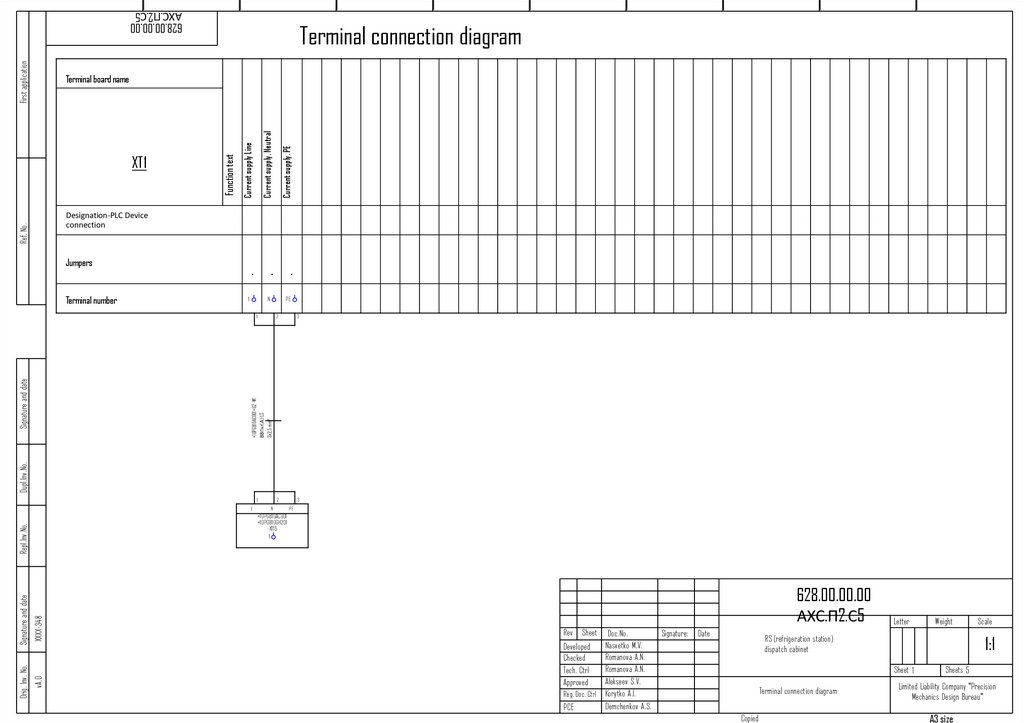
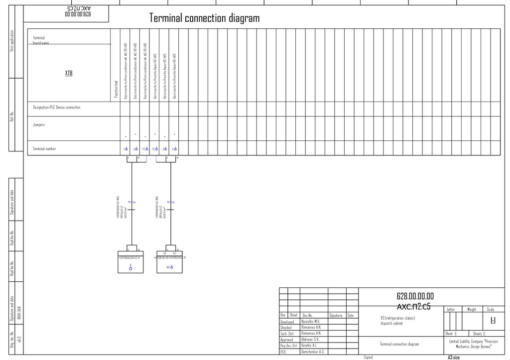
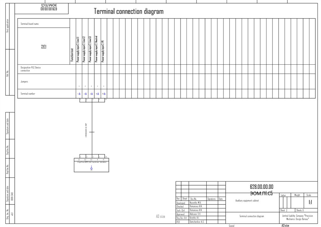
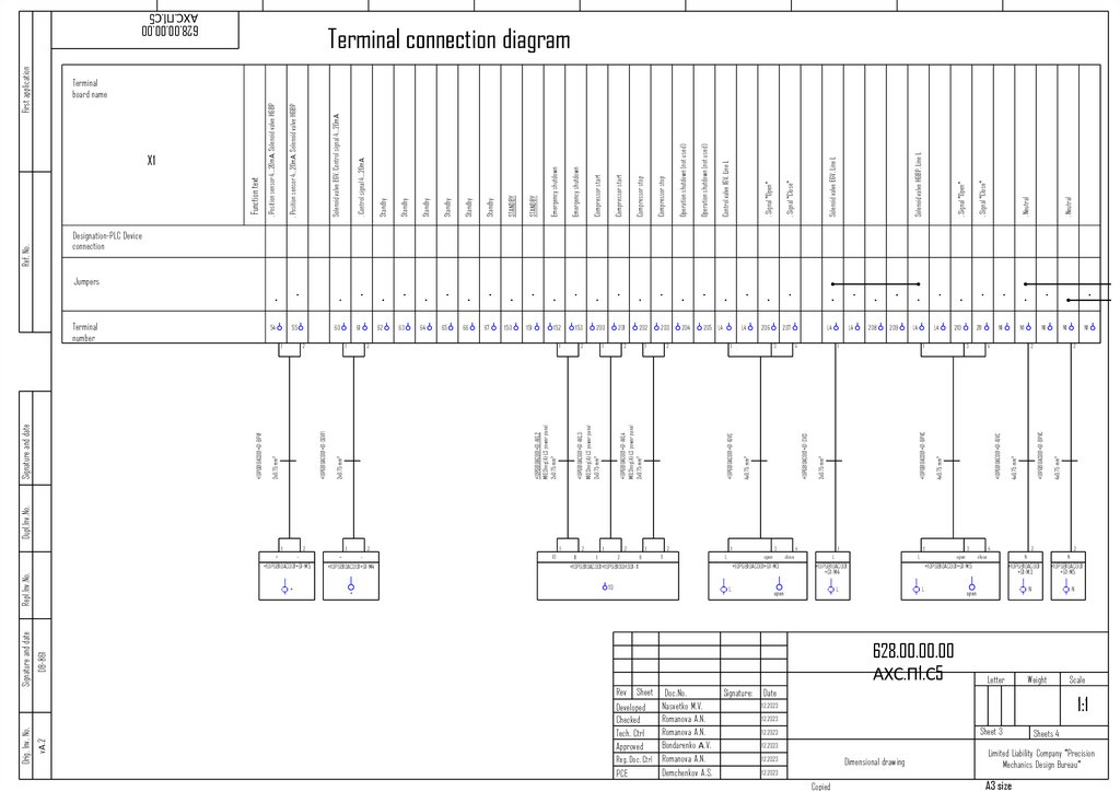
33.
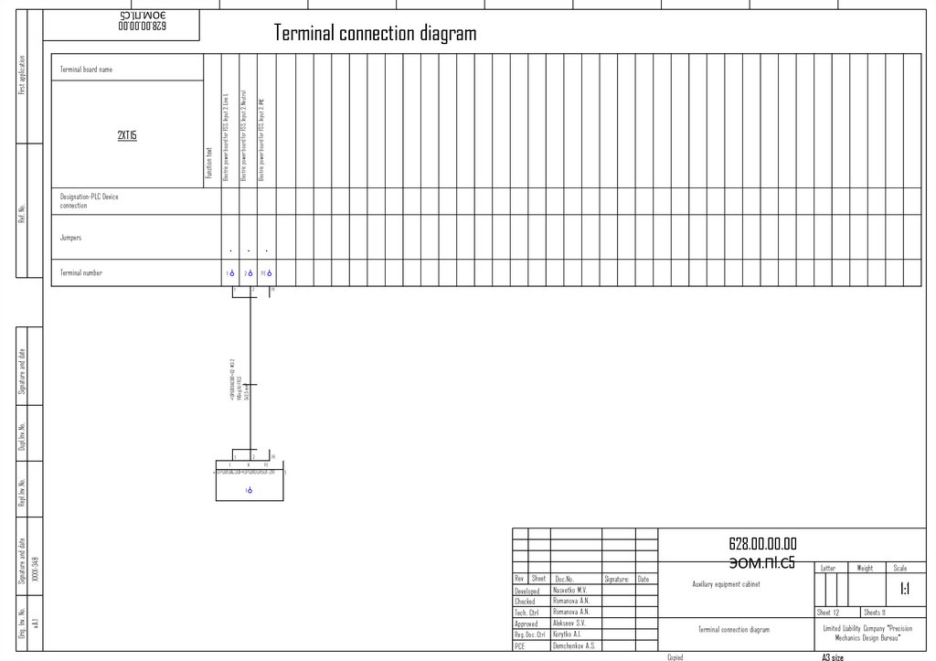
Terminal connection diagramPower supply input from ПЭСПЗ (power supply equipment of
the protection system) PE
Function text
Power supply input from ПЭСПЗ (power supply equipment of
the protection system) Neutral
First application
XT1
Power supply input from ПЭСПЗ (power supply equipment of
the protection system) Line L1
628.00.00.00.00 PS.P1.S5
Terminal board name
-
-
-
1
N
Ref. No.
PLC designation
Devices connected
3x2.5 mm2
PE
Dupl.Inv.No.
+locally-W1*
Signature and date
Terminal number
BBГ-НГ(A)-FRLS
Jumpers
хххх
628.00.00.00.00 PS.P1.S5
v.А.2
Orig. Inv. No.
Signature and date
Repl.Inv.No.
+locally-ПЭСПЗ (power supply
panel for electrical equipment of
fire protection systems)
Letter
Rev Sheet Doc.No.
.
Arsentieva A.R
Developed
Romanova
A.N.
Checked
Romanova A.N.
Tech. Ctrl
Alekseev S.V.
Approved
Reg. Doc. Ctrl Romanova A.N.
Demchenkov A.S.
PCE
Signature:
Date
/signature/
10.2023
/signature/
10.2023
/signature/
10.2023
/signature/
10.2023
/signature/
10.2023
/signature/
10.2023
Weight
Fire Alarm Board АШУ23-001-
1:1
54-ШПС-628
Sheet1
Terminal connection diagram
Copied
Scale
Sheets 5
Limited Liability Company "Precision
Mechanics Design Bureau"
A3 size
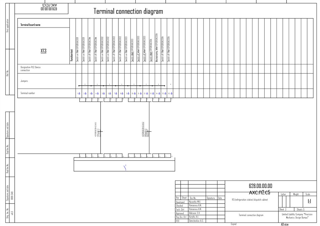
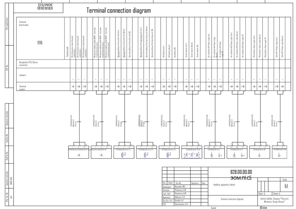
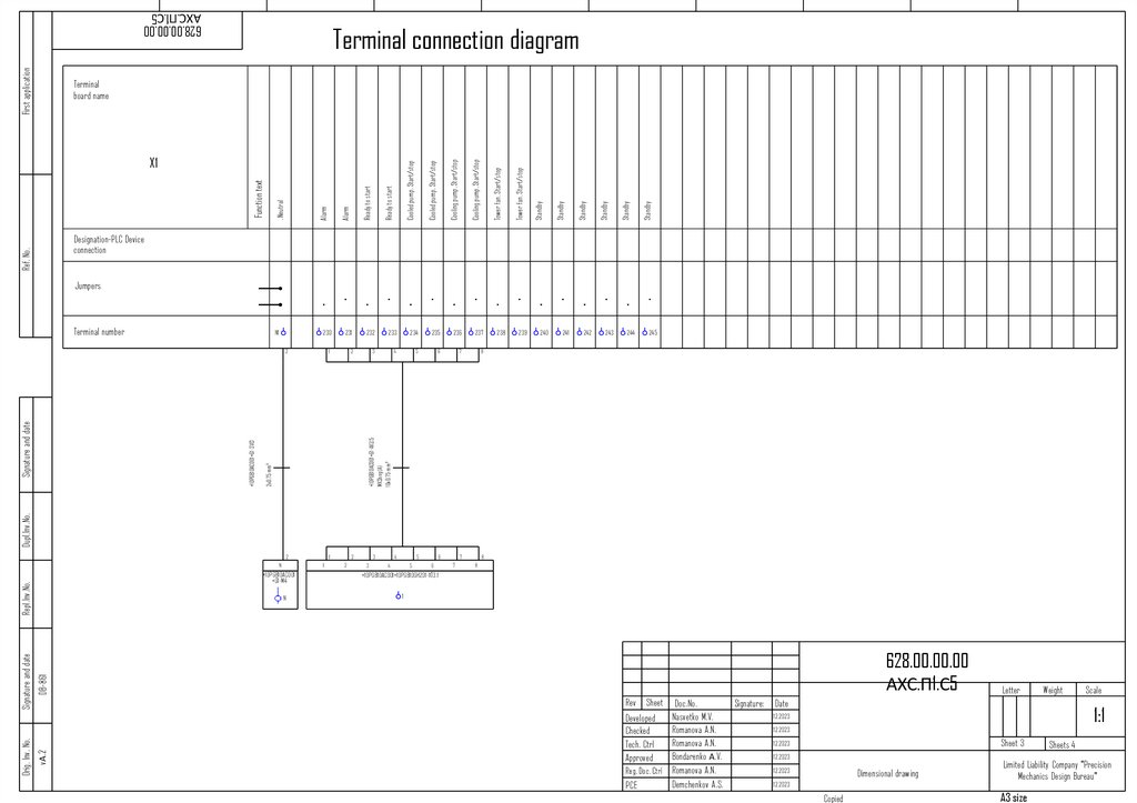
34.
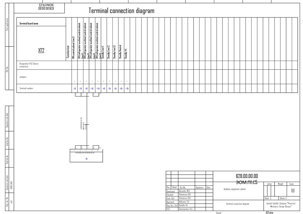
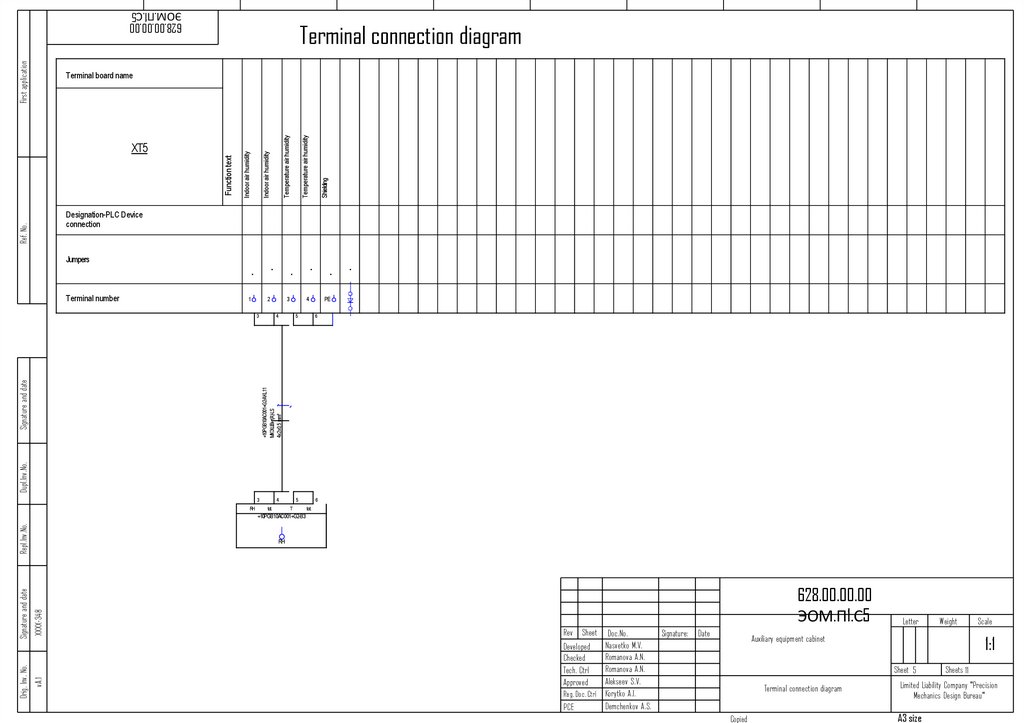
Terminal connection diagramFirst application
628.00.00.00.00 PS.P1.S5
Power supply for fire alarm sirens
Power supply for fire alarm sirens
Power supply for fire alarm sirens
Power supply for fire alarm sirens
Power supply for fire alarm sirens
Power supply for fire alarm sirens
Power supply for fire alarm sirens
Function text
XT5
Power supply for fire alarm sirens
Terminal board name
Ref. No.
Designation-PLC Device connection
Jumpers
+Machinery hall-FDSWK17
ВВГнг(А)-FRLS
3x1.5 mm²
+Machinery hall-FDSWK1
ВВГнг(А)-FRLS
3x1.5 mm²
+outside BК-FDS-WK13
KSRVng(А)-FRLS
1х2x0,8 mm²
Dupl.Inv.No.
+Machinery hall-FDSWK5
KSRVng(А)-FRLS
1х2x0,8 mm²
Signature and date
Terminal number
+outside BK-BTM1
+Machinery hallBIALS1
+Machinery
hall-KK1
хххх
628.00.00.00.00 PS.P1.S5
v.А.2
Orig. Inv. No.
Signature and date
Repl.Inv.No.
+Machinery hallBTK1
Letter
Rev Sheet Doc.No.
.
Arsentieva A.R
Developed
Romanova
A.N.
Checked
Romanova A.N.
Tech. Ctrl
Alekseev S.V.
Approved
Reg. Doc. Ctrl Romanova A.N.
Demchenkov A.S.
PCE
Signature:
Date
/signature/
10.2023
/signature/
10.2023
/signature/
10.2023
/signature/
10.2023
/signature/
10.2023
/signature/
10.2023
Weight
Fire Alarm Board АШУ23-001-
1:1
54-ШПС-628
Sheet2
Sheets 5
Limited Liability Company "Precision
Mechanics Design Bureau"
Terminal connection diagram
Copied
Scale
A3 size
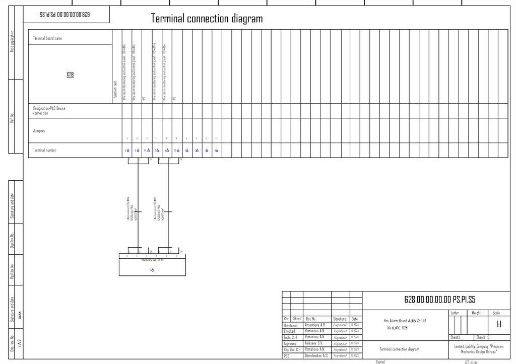
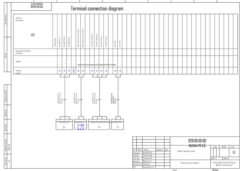
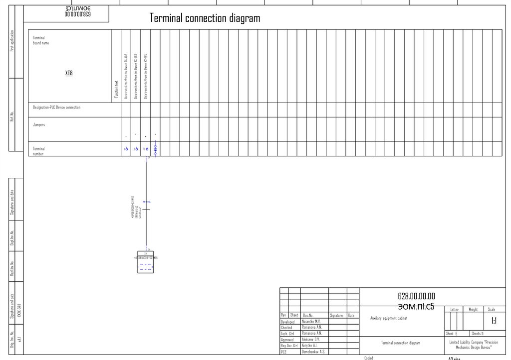
35.
Terminal connection diagramFirst application
628.00.00.00.00 PS.P1.S5
Fire alarm monitoring and control panel. RS-485-1
PE
Fire alarm monitoring and control panel. RS-485-2
Fire alarm monitoring and control panel. RS-485-1
PE
Function text
XT8
Fire alarm monitoring and control panel. RS-485-1
Terminal board name
5
6
PE
7
8
PE
Ref. No.
Designation-PLC Device
connection
Jumpers
2
SH
1
2
2
3
4
SH
Dupl.Inv.No.
+Machinery hall-FDS-WK14
KPSESng(A)-FRLS
1х2x0.75 mm²
Signature and date
1
1
+Machinery hall-FDS-WK15
KPSESng(A)-FRLS
1х2x0.75 mm²
Terminal number
1
5
2
6
SH
7
1
8
2
6
SH
7
5
хххх
628.00.00.00.00 PS.P1.S5
v.А.2
Orig. Inv. No.
Signature and date
Repl.Inv.No.
+Machinery hall-PU1-XT1
Letter
Rev Sheet Doc.No.
.
Arsentieva A.R
Developed
Romanova
A.N.
Checked
Romanova A.N.
Tech. Ctrl
Alekseev S.V.
Approved
Reg. Doc. Ctrl Romanova A.N.
Demchenkov A.S.
PCE
Signature:
Date
/signature/
10.2023
/signature/
10.2023
/signature/
10.2023
/signature/
10.2023
/signature/
10.2023
/signature/
10.2023
Weight
Fire Alarm Board АШУ23-001-
1:1
54-ШПС-628
Sheet3
Terminal connection diagram
Copied
Scale
Sheets 5
Limited Liability Company "Precision
Mechanics Design Bureau"
A3 size
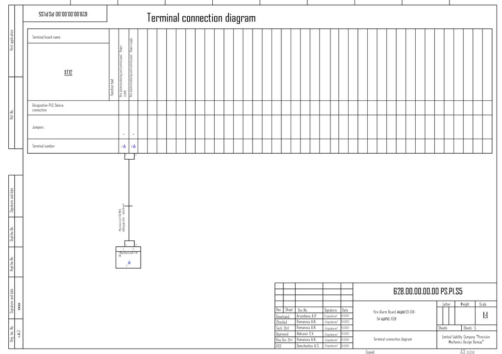
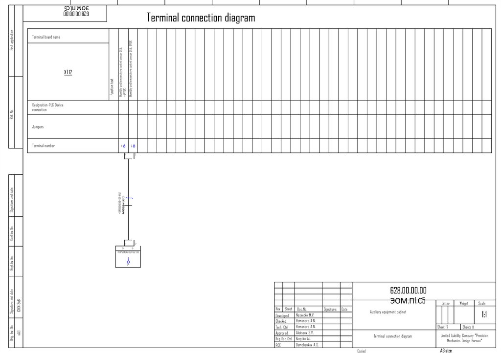
36.
Terminal connection diagramFirst application
628.00.00.00.00 PS.P1.S5
Fire alarm monitoring and control panel. Power supply
Function text
XT12
Fire alarm monitoring and control panel. Power
supply
Terminal board name
1
2
Ref. No.
Designation-PLC Device
connection
Jumpers
Terminal number
2
Dupl.Inv.No.
+Machinery hall-FDS-WK16
KSRVng(А)-FRLS 1х2x0,8 mm²
Signature and date
1
1
2
1
+Machinery hall-PU1XT1
Repl.Inv.No.
1
хххх
628.00.00.00.00 PS.P1.S5
v.А.2
Signature and date
Orig. Inv. No.
2
Letter
Rev Sheet Doc.No.
.
Arsentieva A.R
Developed
Romanova
A.N.
Checked
Romanova A.N.
Tech. Ctrl
Alekseev S.V.
Approved
Reg. Doc. Ctrl Romanova A.N.
Demchenkov A.S.
PCE
Signature:
Date
/signature/
10.2023
/signature/
10.2023
/signature/
10.2023
/signature/
10.2023
/signature/
10.2023
/signature/
10.2023
Weight
Fire Alarm Board АШУ23-001-
1:1
54-ШПС-628
Sheet4
Terminal connection diagram
Copied
Scale
Sheets 5
Limited Liability Company "Precision
Mechanics Design Bureau"
A3 size
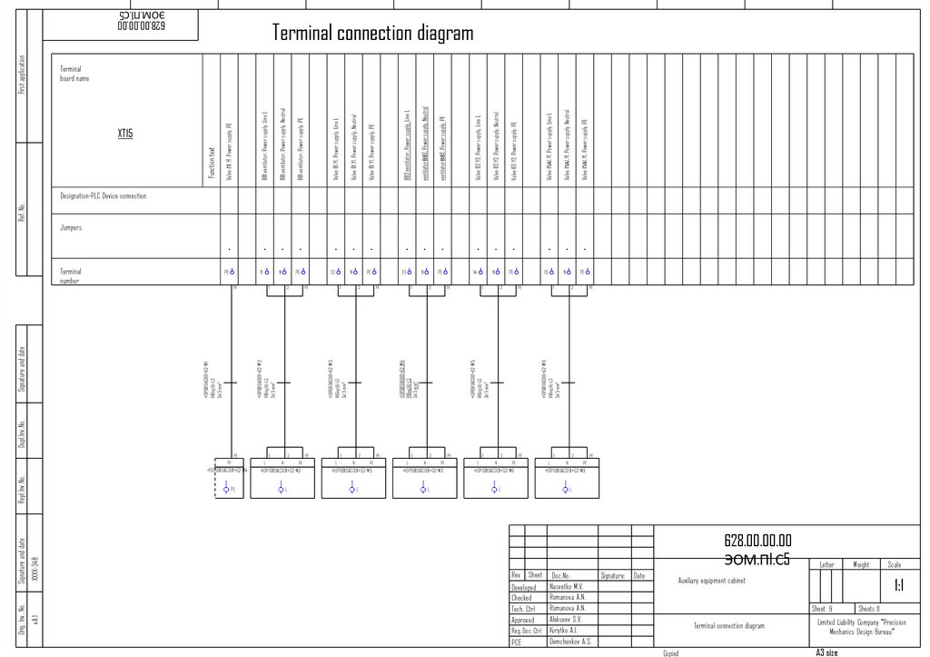
37.
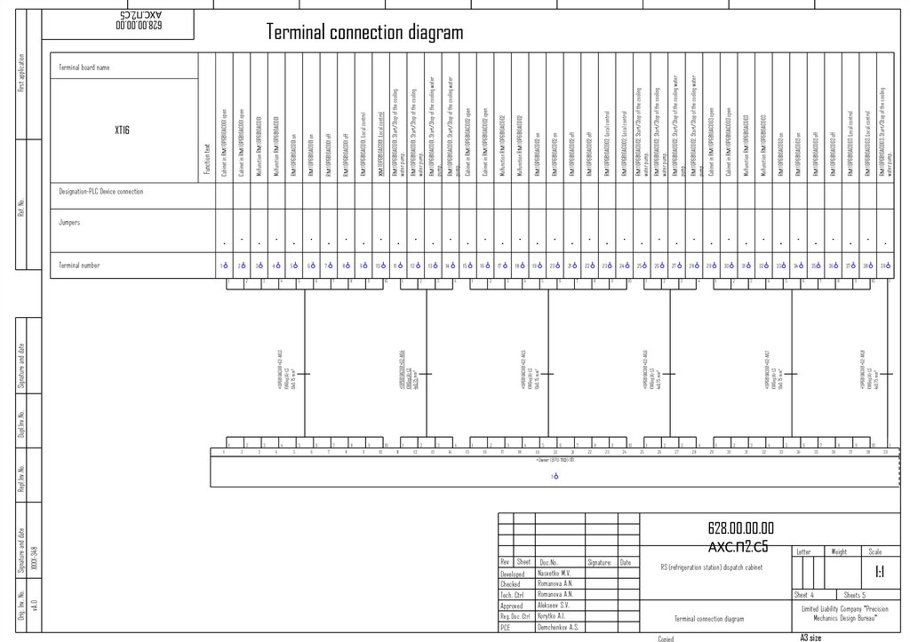
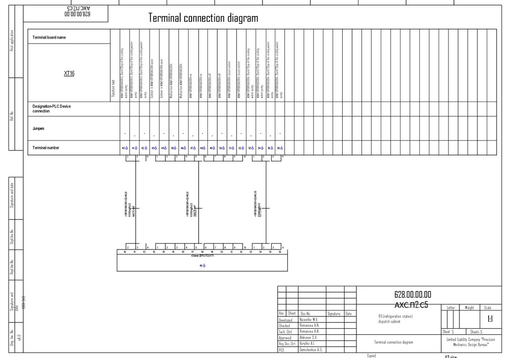
Terminal connection diagramFirst application
628.00.00.00.00 PS.P1.S5
Auxiliary equipment cabinet Alarm: FIRE
PE
Automation cabinet. Alarm: FIRE
Automation cabinet. Alarm: FIRE
PE
To the Customer's system. Alarm: "Fire"
To the Customer's system. Alarm: "Fire"
PE
Function text
XT16
Auxiliary equipment cabinet Alarm: FIRE
Terminal board name
1
2
PE
3
4
PE
5
6
PE
Ref. No.
Designation-PLC Device connection
Jumpers
1
2
1
2
1
2
15
16
+locally-ShSN-XT3
1
2
119
120
+locally-ShA-XT3
1
2
119
120
+locally-ShPA-XT3
15
119
119
хххх
628.00.00.00.00 PS.P1.S5
v.А.2
Orig. Inv. No.
Signature and date
Repl.Inv.No.
Dupl.Inv.No.
+locally-FDS3
KPSESng(A)-FRLS
1х2x0.75 mm²
2
+locally-FDS1
KPSESng(A)-FRLS
1х2x0.75 mm²
Signature and date
1
+locally-FDS2
KPSESng(A)-FRLS
1х2x0.75 mm²
Terminal number
Letter
Rev Sheet Doc.No.
.
Arsentieva A.R
Developed
Romanova
A.N.
Checked
Romanova A.N.
Tech. Ctrl
Alekseev S.V.
Approved
Reg. Doc. Ctrl Romanova A.N.
Demchenkov A.S.
PCE
Signature:
Date
/signature/
10.2023
/signature/
10.2023
/signature/
10.2023
/signature/
10.2023
/signature/
10.2023
/signature/
10.2023
Weight
Fire Alarm Board АШУ23-001-
1:1
54-ШПС-628
Sheet5
Terminal connection diagram
Copied
Scale
Sheets 5
Limited Liability Company "Precision
Mechanics Design Bureau"
A3 size
38.
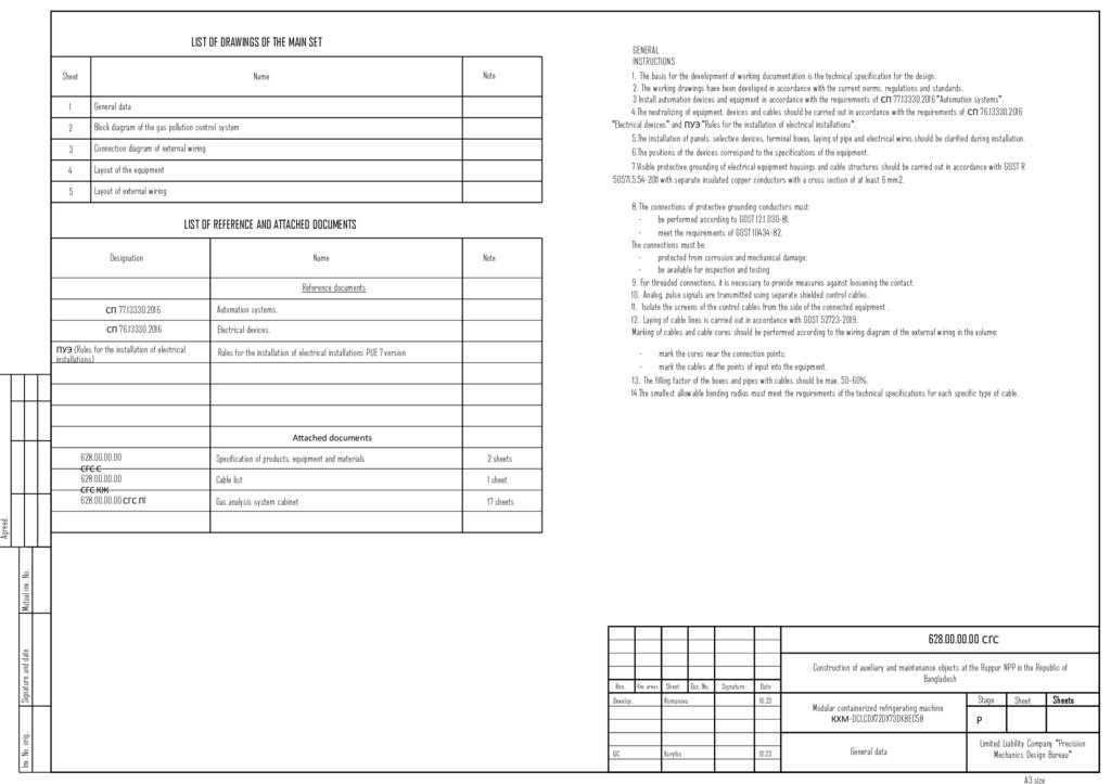
LIST OF DRAWINGS OF THE MAIN SETSheet
Note
Name
1
General data
2
Block diagram of the gas pollution control system
3
Connection diagram of external wiring
4
Layout of the equipment
5
Layout of external wiring
GENERAL
INSTRUCTIONS
1. The basis for the development of working documentation is the technical specification for the design.
2. The working drawings have been developed in accordance with the current norms, regulations and standards.
3 Install automation devices and equipment in accordance with the requirements of СП 77.13330.2016 "Automation systems".
4.The neutralizing of equipment, devices and cables should be carried out in accordance with the requirements of СП 76.13330.2016
"Electrical devices" and ПУЭ "Rules for the installation of electrical installations".
5.The installation of panels, selective devices, terminal boxes, laying of pipe and electrical wires should be clarified during installation.
6.The positions of the devices correspond to the specifications of the equipment.
7.Visible protective grounding of electrical equipment housings and cable structures should be carried out in accordance with GOST R
50571.5.54-2011 with separate insulated copper conductors with a cross section of at least 6 mm2.
8. The connections of protective grounding conductors must:
be performed according to GOST 12.1.030-81;
meet the requirements of GOST 10434-82.
The connections must be:
protected from corrosion and mechanical damage;
be available for inspection and testing.
9. For threaded connections, it is necessary to provide measures against loosening the contact.
10. Analog, pulse signals are transmitted using separate shielded control cables.
11. Isolate the screens of the control cables from the side of the connected equipment .
12. Laying of cable lines is carried out in accordance with GOST 52723-2019.
Marking of cables and cable cores should be performed according to the wiring diagram of the external wiring in the volume:
LIST OF REFERENCE AND ATTACHED DOCUMENTS
Designation
Name
Note
Reference documents
СП 77.13330.2016
Automation systems.
СП 76.13330.2016
Electrical devices.
ПУЭ (Rules for the installation of electrical
installations)
Rules for the installation of electrical installations PUE 7 version
mark the cores near the connection points;
mark the cables at the points of input into the equipment.
13. The filling factor of the boxes and pipes with cables should be max. 50-60%.
14.The smallest allowable bending radius must meet the requirements of the technical specifications for each specific type of cable.
Attached documents
Specification of products, equipment and materials
2 sheets
Cable list
1 sheet
Gas analysis system cabinet
17 sheets
Mutual inv. No.
Agreed.
628.00.00.00
СГС.С
628.00.00.00
СГС.КЖ
628.00.00.00 СГС.П1
Inv. No. orig.
Signature and date
628.00.00.00 СГС
Rev.
Develop.
QC
Rev. areas. Sheet
Romanova
Korytko
Doc. No.
Signature:
Date
10.23
10.23
Construction of auxiliary and maintenance objects at the Ruppur NPP in the Republic of
Bangladesh
Modular containerized refrigerating machine
КХМ-DCLCDX72DX73DK8EC58
General data
Stage
Sheet
Sheets
Р
Limited Liability Company "Precision
Mechanics Design Bureau"
A3 size
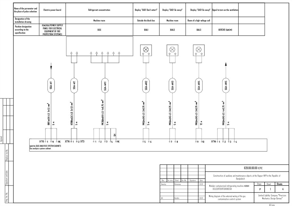
39.
Name of the parameter andthe place of pulse selection
Electric power board
Designation of the
installation drawing
ПЭСПЗ (POWER SUPPLY
PANEL FOR ELECTRICAL
EQUIPMENT OF FIRE
PROTECTION SYSTEMS)
Display "GAS! Don't enter!"
Display "GAS! Go away!"
Display "GAS! Go away!" Signal to turn on the ventilation
Machine room
Outside the block box
Machine room
Room of a high-voltage cell
BGG
BIAL1
BIAL2
BIAL3
AUXCAB (ШСН)
Replace inv.No.
Agreed.
Position designation
according to the
specification
Refrigerant concentration
ШСГА (GAS ANALYSIS SYSTEM CABINET)
Gas analysis system cabinet
Orig. Inv. No.
Signature and date
628.00.00.00 СГС
Rev.
Develop.
QC
Rev. areas. Sheet
Romanova
Korytko
Doc. No.
Signature:
Date
10.23
10.23
Construction of auxiliary and maintenance objects at the Ruppur NPP in the Republic of
Bangladesh
Modular containerized refrigerating machine КХМDCLCDX72DX73DK8EC58
Wiring diagram of the external wiring of the gas
contamination control system
Stage
Sheet
Р
1
Sheets
4
Limited Liability Company "Precision
Mechanics Design Bureau"
A3 size
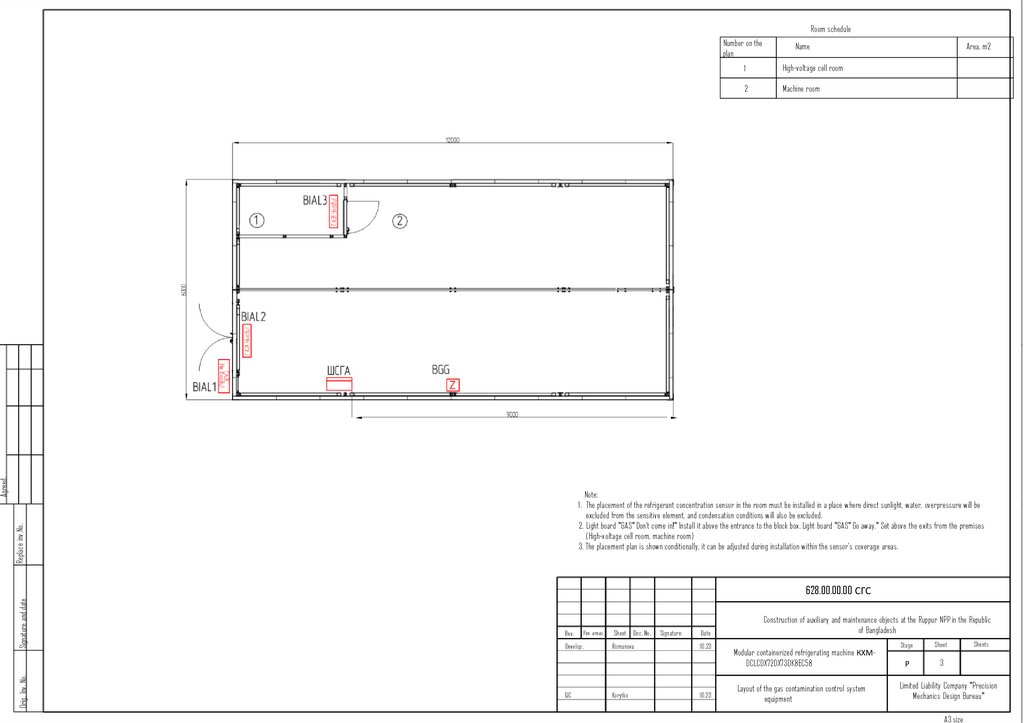
40.
Room scheduleAgreed.
Number on the
plan
Name
1
High-voltage cell room
2
Machine room
Area, m2
Replace inv.No.
Note:
1. The placement of the refrigerant concentration sensor in the room must be installed in a place where direct sunlight, water, overpressure will be
excluded from the sensitive element, and condensation conditions will also be excluded.
2. Light board "GAS" Don't come in!" Install it above the entrance to the block box. Light board "GAS" Go away." Set above the exits from the premises
(High-voltage cell room, machine room)
3. The placement plan is shown conditionally, it can be adjusted during installation within the sensor's coverage areas.
Orig. Inv. No.
Signature and date
628.00.00.00 СГС
Rev.
Rev. areas.
Develop.
QC
Sheet Doc. No.
Romanova
Korytko
Signature:
Date
10.23
10.23
Construction of auxiliary and maintenance objects at the Ruppur NPP in the Republic
of Bangladesh
Modular containerized refrigerating machine КХМDCLCDX72DX73DK8EC58
Layout of the gas contamination control system
equipment
Stage
Sheet
Р
3
Sheets
Limited Liability Company "Precision
Mechanics Design Bureau"
A3 size
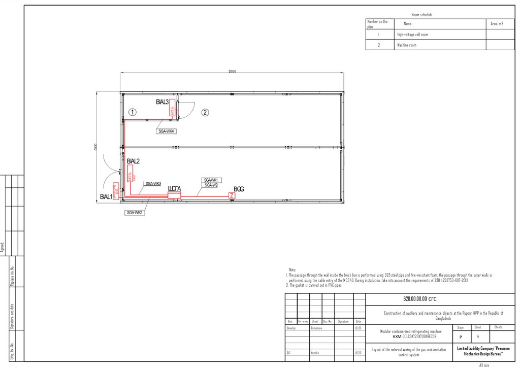
41.
Room scheduleNumber on the
plan
Name
High-voltage cell room
2
Machine room
GAS! Go
away!
GAS! Go
away!
1
Area, m2
Replace inv.No.
Agreed.
GAS!
Don't enter!
Note:
1. The passage through the wall inside the block box is performed using D25 steel pipe and fire-resistant foam, the passage through the outer walls is
performed using the cable entry of the MCS 40. During installation, take into account the requirements of CTO 11233753-007-2012
2. The gasket is carried out in PVC pipes
Orig. Inv. No.
Signature and date
628.00.00.00 СГС
Rev.
Develop.
QC
Rev. areas. Sheet
Romanova
Korytko
Doc. No.
Signature:
Date
10.23
10.23
Construction of auxiliary and maintenance objects at the Ruppur NPP in the Republic of
Bangladesh
Modular containerized refrigerating machine
КХМ-DCLCDX72DX73DK8EC58
Layout of the external wiring of the gas contamination
control system
Stage
Sheet
Р
4
Sheets
Limited Liability Company "Precision
Mechanics Design Bureau"
A3 size
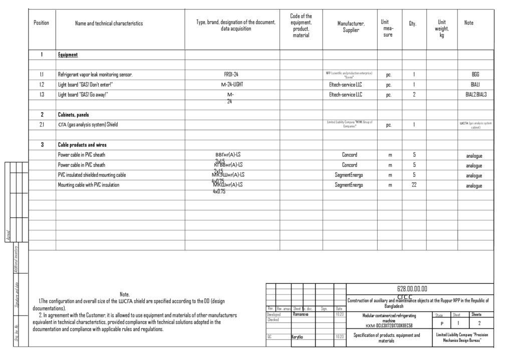
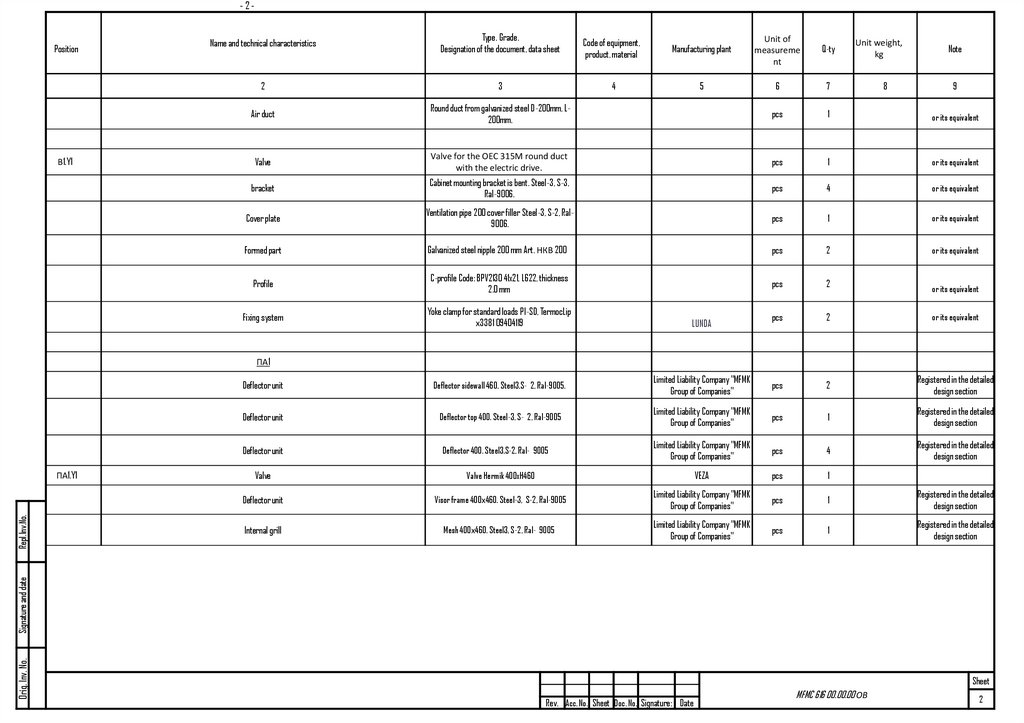
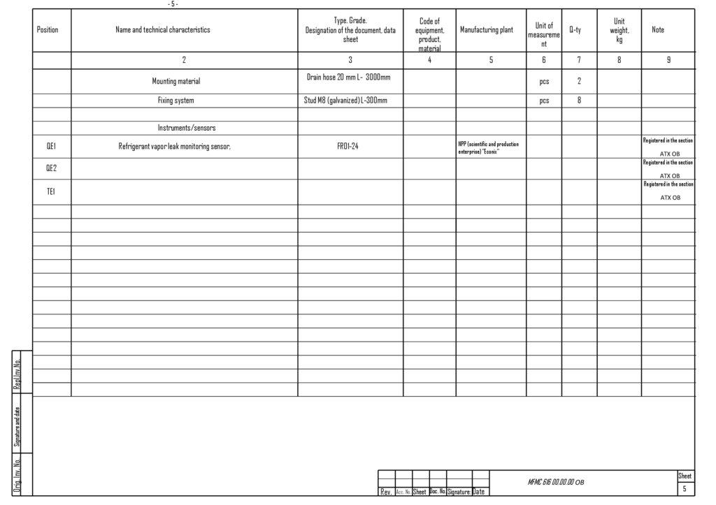
42.
PositionName and technical characteristics
Type, brand, designation of the document,
data acquisition
Code of the
equipment,
product,
material
Manufacturer,
Supplier
Unit
measure
Qty.
NPP (scientific and production enterprise)
"Econix"
pc.
1
BGG
Unit
weight,
kg
Note
1
Equipment
1.1
Refrigerant vapor leak monitoring sensor,
FR01-24
1.2
Light board "GAS! Don't enter!"
М-24-LIGHT
Eltech-service LLC
pc.
1
BIAL1
1.3
Light board "GAS! Go away!"
М24
Eltech-service LLC
pc.
2
BIAL2,BIAL3
2
Cabinets, panels
2.1
СГА (gas analysis system) Shield
Limited Liability Company "MFMK Group of
Companies"
pc.
1
ШСГА (gas analysis system
cabinet)
3
Cable products and wires
Concord
m
5
analogue
Concord
m
5
analogue
SegmentEnergo
m
5
analogue
SegmentEnergo
m
22
analogue
Power cable in PVC sheath
Power cable in PVC sheath
PVC insulated shielded mounting cable
Orig. Inv. No.
Signature and date
Additional inventory
Agreed
Mounting cable with PVC insulation
ВВГнг(А)-LS
3х1.5
КГВВнг(А)-LS
2х1.5
МКЭШнг(А)-LS
4х0.75
МКШнг(А)-LS
4х0.75
Note.
1.The configuration and overall size of the ШСГА shield are specified according to the DD (design
documentations).
2. In agreement with the Customer, it is allowed to use equipment and materials of other manufacturers
equivalent in technical characteristics, provided compliance with technical solutions adopted in the
documentation and compliance with applicable rules and regulations.
628.00.00.00
СГС.С
Construction of auxiliary and maintenance objects at the Ruppur NPP in the Republic of
Rev. Rev. areas. Sheet No. doc.
Romanova
Developed
Checked
QC
Korytko
Sign.
Date
10.23
10.23
Bangladesh
Modular containerized refrigerating
machine
КХМ-DCLCDX72DX73DK8EC58
Specification of products, equipment and
materials
Stage
Sheet
Sheets
Р
1
2
Limited Liability Company "Precision
Mechanics Design Bureau"
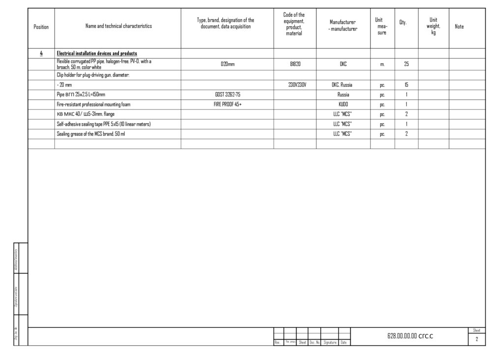
43.
Name and technical characteristicsPosition
4
Electrical installation devices and products
Flexible corrugated PP pipe, halogen-free, PV-0, with a
broach, 50 m, color white
Clip holder for plug-driving gun, diameter:
Type, brand, designation of the
document, data acquisition
Code of the
equipment,
product,
material
Manufacturer
- manufacturer
Unit
measure
Qty.
D20mm
81820
DKC
m.
25
230V230V
DKC, Russia
pc.
15
- 20 mm
GOST 3262-75
Russia
pc.
1
Fire-resistant professional mounting foam
FIRE PROOF 45+
KUDO
pc.
1
КВ МКС 40/ Ш5-31mm, flange
LLC "MCS"
pc.
2
Self-adhesive sealing tape PPE 5x15 (10 linear meters)
LLC "MCS"
pc.
1
Sealing grease of the MCS brand, 50 ml
LLC "MCS"
pc.
2
Note
Orig. Inv. No.
Signature and date
Additional inventory
Pipe ВГП 25х2,5 L=150mm
Unit
weight,
kg
Rev.
Rev. areas.
Sheet Doc. No. Signature: Date
628.00.00.00 СГС.С
Sheet
2
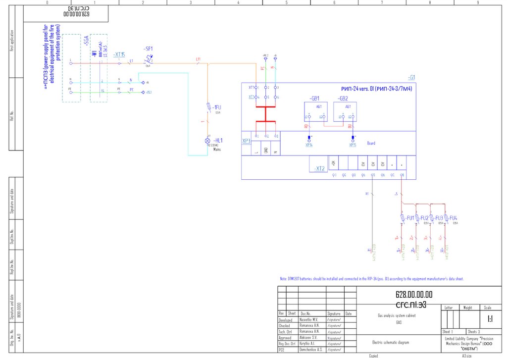
44.
01
2
3
4
5
6
7
8
9
ВВГнг(А)LS 3x1,5
-W1
Ref. No.
First application
=+ПСПЗ (power supply panel for
electrical equipment of the fire
protection system)
628.00.00.00
СГС.П1.Э3
РИП-24 vers. 01 (РИП-24-3/7М4)
Board
X2 220VAC
Repl.Inv.No.
Dupl.Inv.No.
Signature and date
Mains
XXXX-0000
v.А.0
Orig. Inv. No.
Signature and date
Note: DTM1207 batteries should be installed and connected in the RIP-24 (pos. G1) according to the equipment manufacturer's data sheet.
628.00.00.00
СГС.П1.Э3
Rev Sheet Doc.No.
.
Nasvetko M.V.
Developed
Romanova
A.N.
Checked
Romanova A.N.
Tech. Ctrl
Alekseev S.V.
Approved
Reg. Doc. Ctrl Korytko A.I.
Demchenkov A.S.
PCE
Signature:
/signature/
Date
Sheet 1
Electric schematic diagram
/signature/
Copied
Scale
1:1
GAS
/signature/
/signature/
Weight
Gas analysis system cabinet
/signature/
/signature/
Letter
Sheets 3
Limited Liability Company "Precision
Mechanics Design Bureau" (ООО
"ОКБТМ")
A3 size
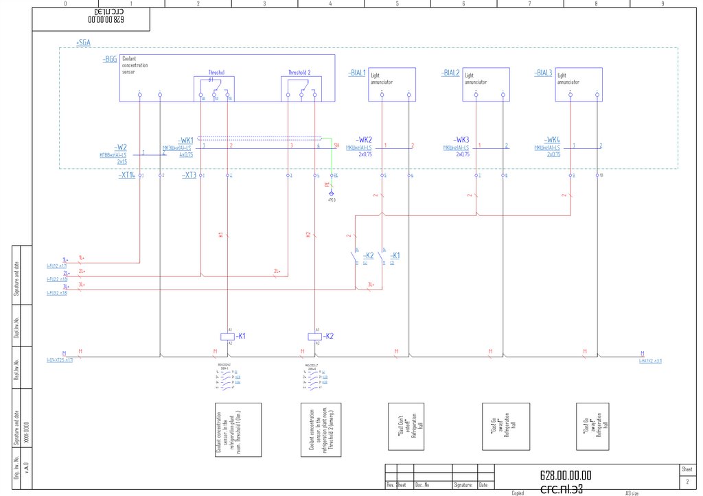
45.
v.А.0Orig. Inv. No.
Threshold 2
5
Rev. Sheet
6
Doc. No
Signature:
Date
Copied
"Gas! Go
away!"
Refrigeration
hall
Threshol
d1
4
"Gas! Go
away!"
Refrigeration
hall
Signature and date
3
"Gas! Don't
enter!"
Refrigeration
hall
Dupl.Inv.No.
Coolant
concentration
sensor
2
Coolant concentration
sensor. In the
refrigeration plant room.
Threshold 2 (emerg.)
Repl.Inv.No.
1
Coolant concentration
sensor. In the
refrigeration plant
room. Threshold 1 (lim.)
XXXX-0000
Signature and date
0
7
8
Light
annunciator
Light
annunciator
Light
annunciator
+
+
+
628.00.00.00
СГС.П1.Э3
9
RKE4CO024LT
SKB14-E
Sheet
2
A3 size
628.00.00.00
СГС.П1.Э3
46.
v.А.0Orig. Inv. No.
Dupl.Inv.No.
Gas contamination
1 threshold
Rev. Sheet
Coolant concentration
sensor. In the
refrigeration plant
room. Threshold 1
(lim.)
Repl.Inv.No.
X2 24VAC/DC
Coolant concentration
sensor. In the
refrigeration plant
room. Threshold 2
(emerg.)
Refrigeration room of the
coolant. In
the concentration
refrigerating (emerg.)
sensor (pre.)
Concentration sensor in
the plant room.
Threshold 1.
Audible warning of the
coolant. In device the
installation Threshold 1
XXXX-0000
Signature and date
Signature and date
0
X2 24VAC/DC
Gas
contamination 2
threshold
Switching on emergency
ventilation
Doc. No
Signature:
Date
Copied
628.00.00.00
СГС.П1.Э3
Sheet
3
A3 size
628.00.00.00
СГС.П1.Э3
47.
628.00.00.00СГС.П1.ГЧ
Door marking
Interior view
XXXX-0000
Note:
1.Unspecified size limits: covered by H14, covered by H14, the rest by JS14
2. Blunt the sharp edges.
v.А.0
Orig. Inv. No.
Signature and date
Repl.Inv.No.
Dupl.Inv.No.
Signature and
date
Marking of door
Rev. Sheet
Doc. No
Signature:
Date
Copied
628.00.00.00
СГС.П1.ГЧ
Sheet
2
A3 size
48.
628.00.00.00СГС.П1.ГЧ
Bottom view
Top view
Marking the cable gland panel
Repl.Inv.No.
Dupl.Inv.No.
Signature and date
Marking the roof
XXXX-0000
Quantity
Diameter, mm
Cable gland
5
16.5
М16 (zeta30111)
1
20.5
М20 (zeta30117)
1
25.5
М25 (zeta30121)
Note:
1.Unspecified size limits: covered by h14, covered by H14, the rest by JS14.
2. Blunt the sharp edges.
v.А.0
Orig. Inv. No.
Signature and date
Designation
Rev. Sheet
Doc. No
Signature:
Date
Copied
628.00.00.00
СГС.П1.ГЧ
Sheet
3
A3 size
49.
v.А.0Orig. Inv. No.
XXXX-0000
Signature and date
Repl.Inv.No.
Dupl.Inv.No.
+SGA-WK4
MKShng(A)-LS
power panel
2x0.75 mm²
First application
Light annunciator.
Light annunciator.
Light annunciator.
Light annunciator.
Light annunciator.
Light annunciator.
Coolant concentration sensor. In the refrigeration
plant room. Threshold 2 (emerg.)
Coolant concentration sensor. Total
Coolant concentration sensor. In the refrigeration
plant room. Threshold 1 (pre.)
Coolant concentration sensor. Total
Function text
XT3
+SGA-WK3
MKShng(A)-LS
power panel
2x0.75 mm²
Ref. No.
Terminal
board name
+SGA-WK2
MKShng(A)-LS
power panel
2x0.75 mm²
+SGA-WK1
MKEShng(A)-LS
4x0,75 mm²
Signature and date
628.00.00.00
СГС.П1.С5
Terminal connection diagram
Designation-PLC Device
connection
Jumpers
Terminal
number
628.00.00.00
СГС.П1.С5
Rev Sheet Doc.No.
.
Nasvetko M.V.
Developed
Romanova
A.N.
Checked
Romanova A.N.
Tech. Ctrl
Alekseev S.V.
Approved
Reg. Doc. Ctrl Korytko A.I.
Demchenkov A.S.
PCE
Signature:
Date
/signature/
/signature/
/signature/
/signature/
/signature/
Terminal connection diagram
Copied
Letter
Sheet 1
Weight
Gas analysis system cabinet
GAS
Sheets 4
/signature/
EDBHM LLC
A3 size
Scale
1:1
50.
First application628.00.00.00
СГС.П1.С5
Terminal connection diagram
Coolant concentration sensor. Power supply 0V
Function text
XT14
Coolant concentration sensor. Power supply 24V
Terminal
board name
1
2
Ref. No.
Designation-PLC Device
connection
Jumpers
1
2
Dupl.Inv.No.
+SGA-W2
KGVVng(A)-LS
2x1.5 mm²
Signature and date
Terminal
number
1
2
+
-
XXXX-0000
+
v.А.0
Orig. Inv. No.
Signature and date
Repl.Inv.No.
+SGA-BGG
628.00.00.00
СГС.П1.С5
Rev Sheet Doc.No.
.
Nasvetko M.V.
Developed
Romanova
A.N.
Checked
Romanova A.N.
Tech. Ctrl
Alekseev S.V.
Approved
Reg. Doc. Ctrl Korytko A.I.
Demchenkov A.S.
PCE
Signature:
/signature/
Date
Weight
Gas analysis system cabinet
Sheet 2
/signature/
/signature/
Terminal connection diagram
Sheets 4
EDBHM LLC
/signature/
Copied
Scale
1:1
GAS
/signature/
/signature/
Letter
A3 size
51.
First application628.00.00.00
СГС.П1.С5
Terminal connection diagram
Terminal board name
Current supply. Line
Current supply. Neutral
Current supply. PE
Function text
XT15
1
N
PE
Ref. No.
Designation-PLC Device
connection
Jumpers
Terminal number
2
PE
Dupl.Inv.No.
+SGA-W1
VVGng(A)-LS
3x1.5 mm²
Signature and date
1
1
2
N
PE
PE
XXXX-0000
L
v.А.0
Orig. Inv. No.
Signature and date
Repl.Inv.No.
L
628.00.00.00
СГС.П1.С5
Rev Sheet Doc.No.
.
Nasvetko M.V.
Developed
Romanova
A.N.
Checked
Romanova A.N.
Tech. Ctrl
Alekseev S.V.
Approved
Reg. Doc. Ctrl Korytko A.I.
Demchenkov A.S.
PCE
Signature:
Date
Letter
Weight
Gas analysis system cabinet
1:1
GAS
Sheet 3
Terminal connection diagram
Copied
Scale
Sheets 4
EDBHM LLC
A3 size
52.
v.А.0Orig. Inv. No.
XXXX-0000
Signature and date
Repl.Inv.No.
Dupl.Inv.No.
+SGA-WK5
MKShng(A)-LS
power panel
4x0,75 mm²
Signature and date
Terminal number
Ref. No.
XT16
Jumpers
1
2
1
1
Coolant concentration sensor. In the refrigeration
plant room. Threshold 1 (pre.)
Designation-PLC Device
connection
Coolant concentration sensor. In the refrigeration
plant room. Threshold 2 (emerg.)
Coolant concentration sensor. In the refrigeration
plant room. Threshold 2 (emerg.)
Coolant concentration sensor. In the refrigeration
plant room. Threshold 2 (emerg.)
Function text
First application
628.00.00.00
СГС.П1.С5
Terminal connection diagram
Terminal board name
3
4
2
2
3
4
3
4
-XT3
628.00.00.00
СГС.П1.С5
Rev Sheet Doc.No.
.
Nasvetko M.V.
Developed
Romanova
A.N.
Checked
Romanova A.N.
Tech. Ctrl
Alekseev S.V.
Approved
Reg. Doc. Ctrl Korytko A.I.
Demchenkov A.S.
PCE
Signature:
/signature/
/signature/
Date
/signature/
/signature/
/signature/
Terminal connection diagram
Copied
Letter
Sheet 4
Weight
Gas analysis system cabinet
GAS
Sheets 4
/signature/
EDBHM LLC
A3 size
Scale
1:1
53.
01
2
3
4
5
6
7
8
9
628.00.00.00ЭМ.П1.Э3
1
First application
L1 2,5 mm²
X1 -HL1
X1 -HL2
230VAC
X2 green input 1.
Power supply
OK
230VAC
X2 green
Signature and date
Ref. No.
Input 1. Operation
7
8
PE
хххх
Power supply input from
220V, 50Hz
AuxCab (ШСН)
v.А.1
Orig. Inv. No.
Signature and date
Repl.Inv.No.
Dupl.Inv.No.
locally
Emergency lighting
220V, 0.115kW, 0.6A
Note:
1.For signal and control circuit wires for which the cross-section is not
specified, use a wire with a cross-section of 0.5 mm².
2. * - cable name and brand shall be specified according to the Customer's
documentation
Fire alarm board
220V, 0.5kW,2А
Gas analysis
system cabinet
220V, 0.5kW,2А
X1 -HL3
X1 -HL4
230VAC
X2 green input 2.
Power supply OK
230VAC
X2 green input 2.
Operation
Standby
628.00.00.00ЭМ.П1.Э3
Rev Sheet Doc.No.
.
Arsentieva A.R
Developed
Romanova
A.N.
Checked
Romanova A.N.
Tech. Ctrl
Alekseev S.V.
Approved
Reg. Doc. Ctrl Korytko A.I.
Demchenkov A.S.
PCE
Signature:
Date
/signature/
10.2023
/signature/
10.2023
/signature/
10.2023
/signature/
10.2023
/signature/
10.2023
/signature/
10.2023
Power supply panel for electrical equipment of fire
protection systems.
ПЭСПЗ (Power supply panel for electrical
equipment of fire protection systems)
Electric schematic diagram
Copied
Letter
Weight
Scale
1:1
Sheet1
Sheets1
Limited Liability Company "Precision
Mechanics Design Bureau"
A3 size
54.
628.00.00.00ЭМ.П1.ГЧхххх
597
v.А.1
Orig. Inv. No.
Signature and date
Repl.Inv.No.
Dupl.Inv.No.
Signature and date
Marking of door
Note.
* - dimensions are for reference and will be specified upon installation. The holes for
the switch handles (pos. QS1-QS2) cut out after installing the mounting plate in the
housing.
When installing the door into the cabinet, reinstall the hinges on the opposite side.
Rev. Sheet
Doc. No
Signature:
Date
Copied
628.00.00.00ЭМ.П1.ГЧ
Sheet
2
A3 size
55.
First application628.00.00.00ЭМ.П1.С5
Terminal connection diagram
Auxiliary equipment cabinet Input 1. Neutral
Auxiliary equipment cabinet Input 1. PE
Function text
1XT1
Auxiliary equipment cabinet Input 1. Line L
Terminal board name
1
2
PE
Ref. No.
Designation-PLC Device
connection
Jumpers
Terminal number
2
PE
Dupl.Inv.No.
-W1*
ВВГнг(А)-FRLS
3x2.5 mm
Signature and date
1
1
2
1
2
PE
PE
хххх
1
v.А.1
Orig. Inv. No.
Signature and date
Repl.Inv.No.
+locally- AuxCab (ШСН)-XT15
628.00.00.00ЭМ.П1.С5
Rev Sheet Doc.No.
.
Arsentieva A.R
Developed
Romanova
A.N.
Checked
Romanova A.N.
Tech. Ctrl
Alekseev S.V.
Approved
Reg. Doc. Ctrl Korytko A.I.
Demchenkov A.S.
PCE
Signature:
Date
10.2023
10.2023
10.2023
Power supply panel for electrical equipment of fire
protection systems.
ПЭСПЗ (Power supply panel for electrical
equipment of fire protection systems)
10.2023
10.2023
Terminal connection diagram
Letter
Weight
1:1
Sheet1
Sheets 3
Limited Liability Company "Precision
Mechanics Design Bureau"
10.2023
Copied
Scale
A3 size
56.
First application628.00.00.00ЭМ.П1.С5
Terminal connection diagram
Auxiliary equipment cabinet Input 2. Neutral
Auxiliary equipment cabinet Input 2. PE
Function text
2XT1
Auxiliary equipment cabinet Input 2. Line L
Terminal board name
1
2
PE
Ref. No.
Designation-PLC Device
connection
Jumpers
Terminal number
2
PE
Dupl.Inv.No.
-W2*
ВВГнг(А)-FRLS
3x2.5 mm
Signature and date
1
1
2
1
2
PE
PE
хххх
1
v.А.1
Orig. Inv. No.
Signature and date
Repl.Inv.No.
+locally- AuxCab (ШСН)-2XT15
628.00.00.00ЭМ.П1.С5
Rev Sheet Doc.No.
.
Arsentieva A.R
Developed
Romanova
A.N.
Checked
Romanova A.N.
Tech. Ctrl
Alekseev S.V.
Approved
Reg. Doc. Ctrl Korytko A.I.
Demchenkov A.S.
PCE
Signature:
Date
/signature/
10.2023
/signature/
10.2023
/signature/
10.2023
/signature/
10.2023
/signature/
10.2023
/signature/
10.2023
Power supply panel for electrical equipment of fire
protection systems.
ПЭСПЗ (Power supply panel for electrical
equipment of fire protection systems)
Terminal connection diagram
Copied
Letter
Weight
Scale
1:1
Sheet2
Sheets 3
Limited Liability Company
"Precision Mechanics Design
Bureau"
A3 size
57.
First application628.00.00.00ЭМ.П1.С5
Terminal connection diagram
Emergency lighting Neutral
Emergency lighting PE
Fire alarm panel. Line L
Fire alarm panel. Neutral
Fire alarm panel. PE
Gas analysis system cabinet. Line L
Gas analysis system cabinet. Neutral
Gas analysis system cabinet. PE
Standby
Neutral
PE
Function text
XT15
Emergency lighting Line L
Terminal board name
1
2
PE
3
4
PE
5
6
PE
7
8
PE
Ref. No.
Designation-PLC Device
connection
Jumpers
2
PE
2
PE
1
2
PE
2
PE
-W5*
VVGng(A)-LS
3x1.5 mm²
1
Dupl.Inv.No.
-W3*
VVGng(A)-LS
3x1.5 mm²
Signature and date
1
-W4*
ВВГнг(А)-FRLS
3x1.5 mm²
Terminal number
1
1
2
1
хххх
PE
PE
+locally- Fire alarm cabinet
(ШОПС)-XT1
1
v.А.1
Orig. Inv. No.
Signature and date
Repl.Inv.No.
+locally-SLA1
2
1
2
1
2
PE
PE
+locally-Gax anal.cab.
(ШСГА)-XT1
1
628.00.00.00ЭМ.П1.С5
Rev Sheet Doc.No.
.
Arsentieva A.R
Developed
Romanova
A.N.
Checked
Romanova A.N.
Tech. Ctrl
Alekseev S.V.
Approved
Reg. Doc. Ctrl Korytko A.I.
Demchenkov A.S.
PCE
Signature:
Date
/signature/
10.2023
/signature/
10.2023
/signature/
10.2023
/signature/
10.2023
/signature/
10.2023
/signature/
10.2023
Power supply panel for electrical equipment of fire
protection systems.
ПЭСПЗ (Power supply panel for electrical
equipment of fire protection systems)
Terminal connection diagram
Copied
Letter
Weight
Scale
1:1
Sheet3
Sheets 3
Limited Liability Company "Precision
Mechanics Design Bureau"
A3 size
58.
General instructionsList of working drawings of the main set
Sheet
Name
The development of this set of documentation is based on the following
documents:
- terms of reference;
- process flow diagram;
- layout of the technological equipment;
- design documentation.
The equipment and materials used in the project are commercially available. It is allowed to
replace equipment with a similar one from another manufacturer and models with the same technical
characteristics, without making changes to the design and estimate documentation, in coordination with
the design organization. When purchasing
The Customer of equipment, products and materials with technical characteristics and parameters
that differ from those specified in the project, may make changes to the developed project
documentation on behalf of the Customer only on a contractual basis.
Note
1
General data
sheet(s) 1
2
Block diagram of the hardware complex
sheet(s) 1
3...4 Automation diagram
sheet(s) 2
5
sheet(s) 1
Layout of electrical equipment and external wiring
List of attached documents
Designation
Name
Note
628.00.00.00 АXC.C1
Specification of equipment, products and
materials
sheet(s) 2
628.00.00.00 АXC.C2
Specification of equipment, products and materials
sheet(s) 1
628.00.00.00
АХС.П1
628.00.00.00
XM (refrigerator machine) control cabinet. Set of diagrams
sheet(s)
XC (refrigeration station) dispatch cabinet Set of diagrams
sheet(s) 27
Securing safety and security.
Protection against electric shock
To ensure the safety of people, all types of protections required by GOST R 50571.3-2009 for
electrical installations of buildings and ПУЭ (Regulations for Electrical Installation) are provided
АХС.П2
List of reference documents
Designation
Orig. Inv. No.
Signature and date
Repl.Inv.No.
Agreed
GOST 21.1101-2013
Name
СПДС (construction design and estimate documentation). Basic
requirements for design and working documentation
GOST 21.208-2013
СПДС (construction design and estimate documentation).
Automation of technological processes. Symbols of conventional
devices and automation tools in circuits
GOST 21.408-2013
СПДС (construction design and estimate documentation). Rules for the
implementation of working documentation for automation of technological
processes
СП 77.13330.2016
Automation systems
ПУЭ (Rules for the installation of electrical
installations)
Rules for the installation of electrical installations (edition 7)
Note
The design documentation complies with the requirements of construction, technological, sanitary and
hygienic and other standards in force on the territory of the Russian Federation, and provides for measures
to ensure structural reliability, explosion and fire safety of the facility and environmental protection during
operation.
Demchenkov A.S.
Chief Engineer of the project
/
628.00.00.00 АТХ
Rev.
Rev. areas.
Developed
Checked
Tech. Ctrl
Approved
Reg. Doc. Ctrl
PCE
Sheet Doc. No. Signature:
/signature/
Romanova
Date
23.10.23
/signature/
23.10.23
/signature/
23.10.23
/signature/
23.10.23
Korytko
/signature/
23.10.23
Demchenkov A.S.
/signature/
23.10.23
Construction of auxiliary and maintenance objects at the Rooppur NPP in
the Republic of Bangladesh
Modular containerized refrigerating
machine
КХМ-DCLCDX72DX73DK8EC58
General data
Stage
Sheet
Sheets
P
1
13
Limited Liability Company "Precision
Mechanics Design Bureau"
A3 size
59.
XM (refrigerator machine) control cabinet.Auxiliary equipment cabinet
RS (refrigeration station) dispatch cabinet
Fire alarm cabinet
Gas contamination system cabinet
Orig. Inv. No.
Signature and date
Repl.Inv.No.
Agreed
Electric power board for FSS
628.00.00.00 АТХ
Rev.
Rev. areas.
Developed
Checked
Tech. Ctrl
Approved
Reg. Doc. Ctrl
PCE
Sheet Doc. No. Signature:
Romanova
Date
23.10.23
23.10.23
23.10.23
Construction of auxiliary and maintenance objects at the Rooppur NPP in
the Republic of Bangladesh
Modular containerized refrigerating
machine
КХМ-DCLCDX72DX73DK8EC58
23.10.23
Korytko
23.10.23
Demchenkov A.S.
23.10.23
Layout of electrical equipment and external
wiring
Stage
Sheet
П
5
Sheets
Limited Liability Company "Precision
Mechanics Design Bureau"
A3 size
60.
First applicationPos.
Name and technical characteristics
Type, brand, designation of
the document, data acquisition
Product code
Supplier
Unit
Q-ty
Weight of 1
unit, kg
Note
Flow measuring devices
F1
.
Presence of coolant flow at the evaporator outlet / Petal flow
relay
1PC,G", flow rate 0.02...1.8 m3/hour, -125...+255 °C,max flow rate-1.6 MPa
ДР-П-35
ДР-П-35-25
OVEN (ОВЕН)
pc.
1
or its equivalent
MIDAS SI
401006/000-460-405
-563-20-11/631
JUMO
pc.
1
or its equivalent
MIDAS SI
401006/000-460-405
-563-20-11/631
JUMO
pc.
1
MIDAS SI
401006/000-460-405
-563-20-11/631
JUMO
pc.
1
MIDAS SI
401006/000-460-405
-563-20-11/631
JUMO
pc.
1
Pressure measuring devices
Ref. No.
P1
P2
P3
P4
.
Pressure on the oil supply to the oil cooler line / Pressure
transformer
0...16bar, 4...20mA, IP67, 7/16-20 UNF internal thread type
.
Compressor Crankcase Pressure /
Pressure transformer
0...16bar, 4...20mA, IP67, 7/16-20 UNF internal thread type
.
Evaporator pressure /
Pressure transformer
0...16bar, 4...20mA, IP67, 7/16-20 UNF internal thread type
.
Condenser pressure /
Pressure transformer
0...16bar, 4...20mA, IP67, 7/16-20 UNF internal thread type
or its equivalent
or its equivalent
or its equivalent
Signature and date
Temperature measuring devices
T1
T2
T4
.
Temperature of the compressor crank case
Temperature sensor (screw-in resistance thermometer) 4...20 mA (Pt100),
G1/2, 0...+50 °C, L-160mm
.
Temperature of heat-carrying agent at the capacitor input
Temperature sensor (screw-in resistance thermometer) 4...20 mA (Pt100),
G1/2, 0...+50 °C, L-160mm
.
Temperature of heat-carrying agent at the capacitor output.
Temperature sensor (screw-in resistance thermometer) 4...20 mA (Pt100),
G1/2, 0...+50 °C, L-160mm
integrated with a compressor
902030
902030/10-402-1001-1-7
-160-104/320,550
JUMO
pc.
1
or its equivalent
902030
902030/10-402-1001-1-7
-160-104/320,550
JUMO
pc.
1
or its equivalent
902030
902030/10-402-1001-1-7
-160-104/320,550
JUMO
pc.
1
or its equivalent
Orig. Inv. No.
Signature and date
Repl.Inv.No.
Dupl.Inv.No.
T3
.
Temperature of the compressor bearing
Rev. Sheet Doc. No
Romanova
Developed
Checked
Approved
Reg. Doc. Ctrl Korytko
Demchenkov A.S.
PCE
Sign.
Date
23.10.23
23.10.23
23.10.23
23.10.23
23.10.23
628.00.00.00 АТХ.C1
Modular containerized refrigerating
machine КХМDCLCDX72DX73DK8EC58
Specification of equipment, products and
materials
Copied
Stage
P
Sheet
1
EDBHM LLC
A3 size
Sheets
2
61.
Pos.Name and technical characteristics
Type, brand, designation of
the document, data acquisition
Product code
Supplier
Unit
Q-ty
Weight of 1
unit, kg
Note
Temperature measuring devices
T5
T6
.
Coolant temperature to the consumer at the evaporator outlet /
Temperature sensor (screw-in resistance thermometer) 4...20 mA (Pt100),
G1/2, 0...50 °C, L-160mm with a 70mm neck
.
Temperature of the compressor electric motor winding
902030
902030/10-402-1001-1-7
-160-104/306,320,550
JUMO
pc.
1
902030
902030/10-402-1001-1-7
-160-104/306,320,550
JUMO
pc.
1
or its equivalent
or its equivalent
integrated into the compressor
electric motor
Orig. Inv. No.
Signature and date
Repl.Inv.No.
Dupl.Inv.No.
Signature and date
T7
.
Coolant temperature from the consumer at the evaporator inlet /
Temperature sensor (screw-in resistance thermometer) 4...20 mA (Pt100),
G1/2, 0...50 °C, L-160mm with a 70mm neck
Rev. Sheet
Doc. No
Signature:
Sheet
628.00.00.00 АТХ.C1
Date
Copied
2
A3 size
62.
First applicationPos.
Name and technical characteristics
Type, brand, designation of
the document, data acquisition
Product code
SR300
Weight of 1
unit, kg
Supplier
Unit
Q-ty
Note
СВ-0047554
СЭВ standard
pc.
1
or its equivalent
FR01-24
FR01-24
NPP (scientific and production
enterprise) "Econix"
pc.
1
or its equivalent
ПВТ110
ПВТ110-H4.А
OVEN (ОВЕН)
pc.
1
or its equivalent
Automation devices and tools
Pressure measuring devices
5.1
.The presence of a pressure drop on the filter F1 / Differential pressure switch 30...300 Pa (15 Pa)
1SPDT, 30…300 Pa (15 Pa), M16x1,5, IP65, -40…+85 °С
Quality measuring devices
QE2
.Indoor Refrigerant Vapor Monitoring / Freon Leak Monitoring Sensor
24V, 2PK
.Indoor humidity and temperature control / Humidity and temperature converter
-40...+80°С, 5...90%, 4...20mA
Orig. Inv. No.
Signature and date
Repl.Inv.No.
Dupl.Inv.No.
Signature and date
Ref. No.
QE1
Rev. Sheet Doc. No
Romanova
Developed
Checked
Approved
Reg. Doc. Ctrl Korytko
Demchenkov A.S.
PCE
Sign.
628.00.00.00 АТХ.C2
Date
23.10.23
23.10.23
23.10.23
23.10.23
23.10.23
Modular containerized refrigerating machine
КХМ-DCLCDX72DX73DK8EC58
Specification of equipment, products and
materials
Copied
Stage
P
Sheet
1
EDBHM LLC
A3 size
Sheets
1
63.
01
2
3
4
5
6
7
8
9
Cont.
220VAC/24VDC, 5A
Chain
Chain
Cont.
+10PGB10AC001+G2
Utility systems (HVA, primary
lighting)
Auxiliary equipment cabinet
Ref. No.
+10PGB10AC001+10PGB10GH201
First application
628.00.00.00
АХС.П2.Э3
MEAN WELL
Signature and date
Control
cabinet /
Socket
Dupl.Inv.No.
Control
cabinet /
Lighting
XXXX-348
vA.0
Orig. Inv. No.
Signature and date
Repl.Inv.No.
Control
cabinet /
Ventilation
628.00.00.00
АХС.П2.Э3
Rev Sheet Doc.No.
.
Nasvetko M.V.
Developed
Romanova
A.N.
Checked
Romanova A.N.
Tech. Ctrl
Alekseev S.V.
Approved
Reg. Doc. Ctrl Korytko A.I.
Demchenkov A.S.
PCE
Signature:
Date
Letter
Weight
1:1
RS dispatch cabinet
Sheet 1
Electric schematic diagram
Copied
Scale
Sheets 11
Limited Liability Company "Precision
Mechanics Design Bureau"
A3 size
64.
01
2
3
4
5
6
7
8
9
628.00.00.00
АХС.П2.Э3
RFT2CO024
SRU08-E
MEAN WELL
Chain
Circuit
(-G1:Output DC:+ sh.1.8)
Input DC
Output DC
(-G1:Output DC:- sh.1.8)
Input DC
Output DC
Cont.
Cont.
Power supply
of the
controller
Operator panel
power supply
of the operator
Bat.-Change,
COM
Bat.-Сhange,
N0
-GB1
Master Kit24VDC/4,5Ah
Chain
Cont.
Industrial switch
power supply
Alarm, COM
Cont.
Circuit
Alarm, NO
Battery
Battery
DC OK, COM
Battery
Battery
DC OK, NO
Digital inputs
power
supply
Signature and date
Digital modules power
supply
Outer input signals
power supply
Dupl.Inv.No.
Standby
XXXX-348
vA.0
Orig. Inv. No.
Signature and date
Repl.Inv.No.
Standby
Rev. Sheet
Doc. No
Signature:
Date
Copied
628.00.00.00
АХС.П2.Э3
Sheet
2
A3 size
65.
01
2
3
4
5
6
7
8
9
628.00.00.00
АХС.П2.Э3
=No.1+Custome
r (BPU-TO)
Switch off ХМ
10PGB10AC004
Switch ХМ
10PGB10AC004
Switch off ХМ
10PGB10AC003
Switch ХМ
10PGB10AC003
Switch off ХМ
10PGB10AC002
Switch on ХМ
10PGB10AC002
Switch off ХМ
10PGB10AC001
Switch on ХМ
10PGB10AC001
XXXX-348
vA.0
Orig. Inv. No.
Signature and date
Repl.Inv.No.
Dupl.Inv.No.
Signature and date
=No.1+10PGB10AC001+G2
Utility systems (HVA, working
lighting)
*-Owner's cable. The cable brand and designation is subject to clarification according to the Owner's
documentation.
Rev. Sheet
Doc. No
Signature:
Date
Copied
628.00.00.00
АХС.П2.Э3
Sheet
3
A3 size
66.
01
2
3
4
5
6
7
8
9
628.00.00.00
АХС.П2.Э3
Operator panel
power supply
Power supply to
the switch
Data transfer via
Ethernet
MT8106iP
USB
PE
-PE:8
(-XT0:3 sh.2.9)
(-XT0:2 sh.2.9)
3L+
3L+
3M
3M
Utility systems (HVA, primary
lighting)
=No.1+10PGB10AC001+G2
=No.1+10PGB10AC001+10PGB10GH001
RM control cabinet
-XT
Air conditioner
Signature and date
-XT8
KIPEVng(A)-LS
1х2x0.6
1
2
(-FU1:2 sh.2.6)
1M
PE
k
Utility systems (HVA,
working lightning)
bk
SH
1M
-XT8
1M
3
4
PE
FTP
4х2x0.41
Repl.Inv.No.
TA
T/RB
TB
RTS
Siemens
Data transfer to/from
conditioners К1, К2
-A1
FTP
4х2x0,41
-1WE3
FTP
4х2x0.41
-1WE4
FTP
4х2x0.41
FTP
4х2x0.41
-A2
-X10
L+
1
M
2
FE
3
1M
6 -X12
6ES7215-1AG40-0XB0
Power supply to CPU
4L+
1
4M
2
X20
M
1
TA
2
T_RA
3
T_RB
4
TB
5
(s.5.0) (s.6.0)
(sh.6.0
)
RTS
6
Siemens
DC/DC/DC
Data transfer
via Ethernet
Data transfer to/from control
cabinet RМ via RS-485
Data transfer via
Ethernet
vA.0
XXXX-348
T/RA
-1WE2
FTP
4х2x0,41
-Eth2
PE
Dupl.Inv.No.
SH
KIS-Vng(A)-LS
1х2x0,6
-PE:7
-Eth1
-PE:9
-2
SH
KIS-Vng(A)-LS
1х2x0,6
-1WE1
-PE:10
-PE:9
-1
=No.1+10PGB10AC001+G2
Utility systems (HVA,
working lightning)
=No.1+10PGB10AC001+G2
1L+
-PE:12 (-XT0:1 sh.2.9)
6ES7241-1CH32-0XB0
Signature and date
-1WE5
SH
1L+ 1L+
M
Orig. Inv. No.
bk
902
Rev. Sheet
Doc. No
Signature:
=No.1+10PGB10AC004+10PGB10GH204
Auxiliary equipment cabinet
k
901
=No.1+10PGB10AC003+10PGB10GH203
Auxiliary equipment cabinet
-1WE6
KIPEVng(A)-LS
1х2x0.6
-PE:11
=No.1+10PGB10AC002+10PGB10GH202
Auxiliary equipment cabinet
-K1
GND
=No.1+10PGB10AC001+10PGB10GH201
Auxiliary equipment cabinet
2M
2M
-A5
EDS-208
US
(-FU3:2 sh.2.6)
(-FU2:2 sh.2.6)
MOXA
PE
2L+
2L+
COM1/
COM2
FG
-A6
Eth
-
USB Host
24VDC
+
RS232/
RS485
24VDC
Weintek
Data transfer via
Ethernet
Date
Copied
628.00.00.00
АХС.П2.Э3
Sheet
4
A3 size
67.
vA.0Orig. Inv. No.
XXXX-348
Signature and date
14 (s.3.3)
DI a.7
14
Rev. Sheet
-K7
DI b.0
15
DIa
Doc. No
11
14 (s.3.4)
Signature:
7
-K8
11
14 (s.3.4)
DI b.1
16
DI b.2
17
Date
Copied
4L+
-K9
11
14 (s.3.5)
-K10
DI b.3
18
Siemens 6ES7215-1AG40-0XB0
11
14 (s.3.6)
-K11
14 (s.3.7)
DI b.4
19
628.00.00.00
АХС.П2.Э3
Switch off ХМ
10PGB10AC004
11
4L+
X14
-K6
4L+
X13
14 (s.3.2)
4L+
X12
11
6
Switch on ХМ
10PGB10AC004
DI a.6
13
4L+
X11
-K5
X10
11
X9
(-G2:DC OK, NO:6 sh.2.4)
4L+
Switch off ХМ
10PGB10AC003
DI a.5
12
5
Switch on ХМ
10PGB10AC003
DI a.4
11
X6
(-G2:Alarm, NO:4 sh.2.4)
4L+
Switch off ХМ
10PGB10AC002
DI a.3
10
4
Switch on ХМ
10PGB10AC002
DI a.2
9
X8
-K4
(-G2:Alarm, COM:3 sh.2.4)
4L+
Switch off ХМ
10PGB10AC001
14 (s.1.8)
X7
11
-K3
X6
14 (s.1.4)
3
Switch on ХМ
10PGB10AC001
DI a.1
8
11
X5
-K2
(-G2:Bat.-Сhange, N0:2 sh.2.4)
4L+
4L+
X5
14 (s.1.4)
2
24VDC power
supply is OK
DI a.0
11
X4
-K1
X4
X3-1
11
X3
4L+
Battery low
(G2)
-X10 7
X2
X1
1
Power supply of
internal control
circuits from the
battery (G2)
Signature and date
4L+
Faulty power
supplies (G1, G2)
Dupl.Inv.No.
4L+
Control
cabinet
open
Presence of
voltage in
220VAC circuits
Repl.Inv.No.
0
8
9
4L+
(-FU4:2 sh.2.6)
11
14 (s.3.8)
-K12
14 (s.2.4)
DI b.5
20
-A2
(sh.4.1)
DIb
Part 2 of 3
Sheet
5
A3 size
628.00.00.00
АХС.П2.Э3
68.
01
2
3
4
5
6
7
8
9
628.00.00.00
АХС.П2.Э3
Siemens 6ES7215-1AG40-0XB0
Part 3 of 3
Signature and date
A2
A1
-K13
4M
A2
4M
A2
A1
-K15
4M
A2
4M
A2
A1
-K17
4M
10
DQ a.7
A2
A1
-K18
4M
11
DQ b.0
A2
A1
-K19
4M
A2
4M
1
2M
2
AI 0
3
AI 1
Y10
A1
-K20
-X11
12
DQ b.1
Y9
Y7
Y6
A1
-K16
9
DQ a.6
Y8
8
DQ a.5
Y5
Y4
A1
-K14
7
DQ a.4
A1
-K21
A2
4M
-K22
A2
4M
(-XT0:4 sh.2.9)
24
11 (s.10.3)
14
21
24
RFT2CO024
SRU08-E
11 (s.10.3)
14
21
24
RFT2CO024
SRU08-E
11 (s.10.4)
14
21
24
RFT2CO024
SRU08-E
11 (s.10.5)
14
21
24
RFT2CO024
SRU08-E
11 (s.10.6)
14
21
24
RFT2CO024
SRU08-E
11 (s.10.6)
14
21
24
RFT2CO024
SRU08-E
11 (s.10.7)
21
Total of analog
inputs
21
RFT2CO024
SRU08-E
vA.0
XXXX-348
Malfunction RМ
10PGB10AC001
Cabinet in RМ
10PGB10AC001
open
14
ХМ 10PGB10AC002
on
24
11 (s.10.2)
Malfunction ХМ
10PGB10AC002
21
RFT2CO024
SRU08-E
Cabinet in ХМ
10PGB10AC002
open
14
RМ 10PGB10AC001.
Start/Stop of
the cooling
water pump.
24
11 (s.10.2)
RМ 10PGB10AC001.
Start/Stop of
the cooling
water pump.
21
RFT2CO024
SRU08-E
RМ 10PGB10AC001.
Local control
14
RМ 10PGB10AC001
off
11 (s.10.1)
Dupl.Inv.No.
24
RFT2CO024
SRU08-E
RМ 10PGB10AC001
on
14
Repl.Inv.No.
Signature and date
Orig. Inv. No.
6
DQ a.3
Standby
A1
4M
5
DQ a.2
Y3
4
DQ a.1
Y2
3
DQ a.0
Y1
-X12
(sh.4.1)
DQb
Standby
DQa
-A2
Rev. Sheet
Doc. No
Signature:
Date
Copied
628.00.00.00
АХС.П2.Э3
Sheet
6
A3 size
69.
01
2
3
4
5
6
7
8
9
628.00.00.00
АХС.П2.Э3
5L+
(-FU5:2 sh.2.6)
5M
5L+
5L+
5M
5M
5M
5M
(-XT0:5 sh.2.9)
5L+
5M
(-A4:-X10:1 sh.9.0)
(-K23:A2 sh.8.0)
PE
-PE:7
Signature and date
-X10 1
L+
M
2
1M
3
DI a.0
4
DI a.1
5
DI a.2
6
DI a.3
7
-X11 8
FE
2M
9
DI a.4
10
DI a.5
11
DI a.6
12
-A3
DI a.7
13
(sh.8.0)
(sh.8.2)
DI a
6ES7223-1BH32-0XB0
DI 8x24VDC / DO 8x24VDC
Part 1 of 2
Signature and date
XXXX-348
Orig. Inv. No.
vA.0
Rev. Sheet
Doc. No
Signature:
Date
Copied
Standby
Standby
Standby
Standby
Total
Standby
Standby
Standby
Standby
Total
Repl.Inv.No.
Power supply
of the
discrete
module of the
I/O module
Dupl.Inv.No.
Siemens
628.00.00.00
АХС.П2.Э3
Sheet
7
A3 size
70.
01
2
3
4
5
6
7
8
9
628.00.00.00
АХС.П2.Э3
Siemens
6ES7223-1BH32-0XB0
-A3
Part 2 of 2
(sh.7.0)
DQa
A1
Signature and date
A2
5M
A1
-K23
5M
A2
5M
A2
A1
-K25
5M
A2
A1
-K26
5M
9
DQ a.6
A2
5M
Y17
A1
-K27
10
DQ a.7
Y18
8
DQ a.5
Y16
Y14
A1
-K24
7
DQ a.4
Y15
6
DQ a.3
A1
-K28
A2
5M
A1
-K29
A2
5M
-K30
A2
5M
5M
(-A3:-X11:9 sh.7.8)
11 (s.10.1)
14
21
24
11 (s.10.2)
14
21
24
11 (s.10.3)
14
21
24
11 (s.10.3)
14
21
24
RFT2CO024
SRU08-E
11 (s.10.4)
14
21
24
RFT2CO024
SRU08-E
(-A4:-X10:2 sh.9.0)
11 (s.10.4)
21
vA.0
XXXX-348
RМ 10PGB10AC003
off
24
RFT2CO024
SRU08-E
RМ 10PGB10AC003
on
14
21
RFT2CO024
SRU08-E
Malfunction RМ
10PGB10AC003
11 (s.10.8)
RFT2CO024
SRU08-E
Cabinet in RМ
10PGB10AC003
open
24
RFT2CO024
SRU08-E
RМ 10PGB10AC002.
Start/Stop of the
cooling water pump.
14
21
RFT2CO024
SRU08-E
RМ 10PGB10AC002.
Start/Stop of the
cooling water
pump.
11 (s.10.8)
ХМ 10PGB10AC002
off
Dupl.Inv.No.
RFT2CO024
SRU08-E
RМ 10PGB10AC002.
Local control
14
24
Repl.Inv.No.
Signature and date
Orig. Inv. No.
5
DQ a.2
Y13
15
DQ a.1
Y12
14
DQ a.0
Y11
-X12
Rev. Sheet
Doc. No
Signature:
Date
Copied
628.00.00.00
АХС.П2.Э3
Sheet
8
A3 size
71.
01
2
3
4
5
6
7
8
9
628.00.00.00
АХС.П2.Э3
-A4
Siemens
6ES7222-1BH32-0XB0
Part 1 of 1
DQa
6
DQ a.6
7
DQ a.7
-X12
4
DQ b.0
5
DQ b.1
6
DQ b.2
7
DQ b.3
-X13
4
DQ b.4
5
DQ b.5
6
DQ b.6
7
DQ b.7
Y28
5
DQ a.5
Y27
4
DQ a.4
Y26
1
FE
Y25
7 -X11
DQ a.3
Y24
6
DQ a.2
Y23
5
DQ a.1
PE
4
DQ a.0
Y22
-X10
Y21
2
M
Y20
1
L+
Y19
-X10
-PE:8
A1
A2
Signature and date
5L+
(-A3:-X10:1 sh.7.8)
5M
5M
A2
A1
-K32
5M
A2
A1
-K33
5M
A2
A1
-K34
5M
A1
-K35
A2
5M
A2
A1
-K36
5M
A1
-K37
A2
5M
A1
-K38
A2
5M
A2
A1
-K39
5M
A2
-K40
5M
(-K30:A2 sh.8.8)
14
21
24
RFT2CO024
SRU08-E
11 (sh.11.2)
14
21
24
RFT2CO024
SRU08-E
11 (sh.11.2)
14
21
24
RFT2CO024
SRU08-E
11 (sh.11.3)
14
21
24
RFT2CO024
SRU08-E
11 (sh.11.3)
14
21
24
RFT2CO024
SRU08-E
11 (sh.11.4)
14
21
24
RFT2CO024
SRU08-E
11 (sh.11.5)
14
21
24
RFT2CO024
SRU08-E
11 (sh.11.6)
21
vA.0
XXXX-348
ХМ 10PGB10AC004.
Start/Stop of the
cooling water
pump.
ХМ
10PGB10AC004.
Start/Stop of the
cooling water
pump.
24
11 (s.10.7)
ХМ 10PGB10AC004.
Local control
21
RFT2CO024
SRU08-E
RМ 10PGB10AC004
off
14
RМ 10PGB10AC004
on
24
11 (s.10.6)
Malfunction RМ
10PGB10AC004
21
RFT2CO024
SRU08-E
Cabinet in RМ
10PGB10AC004
open
14
RМ 10PGB10AC003.
Start/Stop of the
cooling water pump.
11 (s.10.5)
RМ 10PGB10AC003.
Start/Stop of the
cooling water
pump.
Discrete I/O
module power
supply
Dupl.Inv.No.
24
RFT2CO024
SRU08-E
RМ 10PGB10AC003.
Local control
14
Repl.Inv.No.
Signature and date
Orig. Inv. No.
A1
-K31
Rev. Sheet
Doc. No
Signature:
Date
Copied
628.00.00.00
АХС.П2.Э3
Sheet
9
A3 size
72.
01
2
3
4
5
6
7
8
9
628.00.00.00
АХС.П2.Э3
7
8
9
10
3
4
-AKL7*
KVVGng(A)-LS
10x0.75
27
28
34
35
F24
3
4
5
6
7
8
9
10
15
16
17
18
19
20
21
22
23
24
1
2
3
4
5
6
7
8
9
29
30
31
32
33
34
35
36
37
38
Doc. No
F23
2
-AKL8*
Rev. Sheet
F22
1
10 KVVGng(А)-LS
4x0.75
*-Owner's cable. The cable brand and designation is subject to clarification according to the Owner's
documentation.
F21
24
11
-K32
14 (s.9.2)
38
F20
23
11
37
F19
22
-K31
F37
F18
21
14 (s.9.1)
36
F17
F16
F15
F14
F13
F35
F31
F34
F33
33
RМ 10PGB10AC001.
Start/Stop of the
cooling water pump.
RМ 10PGB10AC001.
Start/Stop of the
cooling water pump.
RМ 10PGB10AC001.
Local control
32
14 (s.8.6)
20
-K33
14 (s.9.2)
39
40
41
42
1
2
3
4
39
40
41
42
vA.0
RМ 10PGB10AC002.
Start/Stop of the
cooling water pump.
26
31
11
-K30
19
RМ 10PGB10AC003.
Start/Stop of the
cooling water pump.
2
30
14
RМ 10PGB10AC003.
Local control
1
29
11
-K29
RМ 10PGB10AC003
on
28
13
12
14 (s.8.5)
Malfunction RМ
10PGB10AC003
27
Cabinet in RМ
10PGB10AC003
open
26
11
-K28
14 (s.8.5)
F30
F29
F27
F26
14 (s.8.4)
25
25
11
-K27
F32
11
-K26
14 (s.8.4)
RМ 10PGB10AC002.
Start/Stop of the
cooling water pump.
-XT1
RМ 10PGB10AC001
on
Malfunction RМ
10PGB10AC001
11
-K25
11
18
Signature:
RМ 10PGB10AC002.
Local control
6
-AKL5*
KVVGng(A)-LS
10x0.75
17
ХМ 10PGB10AC002
off
5
4
-K24
14 (s.8.2)
16
RМ 10PGB10AC002
on
4
3
14 (s.8.2)
F42
3
2
11
-K23
15
Malfunction RМ
10PGB10AC002
2
1
14 (s.6.6)
F41
1
14
11
-K22
RМ 10PGB10AC003.
Start/Stop of the
cooling water pump.
9
13
F40
8
12
11
-K21
14 (s.6.5)
Cabinet in RМ
10PGB10AC002
open
7
11
F39
6
RМ 10PGB10AC001
off
5
11
-K20
14 (s.6.5)
F38
10
11
-K19
14 (s.6.4)
F12
F10
F11
F8
F7
F9
9
4
F25
=No.1+10PGB10AC001+G2
-AKL6*
Engineering systems (HVAC, KVVGng(А)-LS
working lightning)
4x0.75
XXXX-348
8
3
F28
Signature and date
Dupl.Inv.No.
7
2
14 (s.8.3)
Repl.Inv.No.
Signature and date
6
1
11
=No.1+Custome
r (BPU-TO)
5
14 (s.6.3)
10 KVVGng(А)-LS
4x0.75
Cabinet in RМ
10PGB10AC001
open
-XT1
-XT16
Orig. Inv. No.
4
14 (s.6.3)
11
-K18
F36
3
14 (s.6.2)
11
-K17
-AKL4*
=No.1+10PGB10AC001+G2
Utility systems (HVA, -AKL3*
working lightning)
KVVGng(A)-LS
10x0.75
=No.1+Custome
r (BPU-TO)
2
11
-K16
RМ 10PGB10AC003
off
1
F5
F2
F1
-XT16
11
-K15
14 (s.6.2)
14 (s.6.1)
F3
14 (s.6.0)
11
-K14
F6
11
-K13
F4
11
Date
Copied
628.00.00.00
АХС.П2.Э3
Sheet
10
A3 size
73.
01
2
3
4
5
6
7
8
9
628.00.00.00
АХС.П2.Э3
48
51
52
-AKL10*
3
4
5
6
7
8
9
43
44
45
46
47
48
49
50
51
52
F56
F54
53
54
55
56
1
2
3
4
53
54
55
56
XXXX-348
vA.0
Orig. Inv. No.
Signature and date
Repl.Inv.No.
Dupl.Inv.No.
ХМ 10PGB10AC004.
Start/Stop of the
cooling water pump.
2
ХМ
10PGB10AC004.
Local control
1
-K40
14 (s.9.7)
F55
14 (s.9.6)
F52
F51
50
11
-K39
F53
14 (s.9.5)
F50
49
11
-K38
ХМ 10PGB10AC004.
Start/Stop of the
cooling water pump.
47
F49
F45
F47
46
14 (s.9.5)
RМ 10PGB10AC004
off
-XT1
45
11
-K37
10 KVVGng(А)-LS
4x0.75
Cabinet in RМ
10PGB10AC004
open
Signature and date
=No.1+Custome
r (BPU-TO)
44
RМ 10PGB10AC004
on
=No.1+10PGB10AC001+G2
Utility systems (HVA, -AKL9*
working lightning)
KVVGng(A)-LS
10x0.75
43
11
-K36
14 (s.9.4)
Malfunction RМ
10PGB10AC004
-XT16
14 (s.9.4)
F44
F43
14 (s.9.3)
11
-K35
F48
11
-K34
F46
11
*-Owner's cable. The cable brand and designation is subject to clarification according to the Owner's
documentation.
Rev. Sheet
Doc. No
Signature:
Date
Copied
628.00.00.00
АХС.П2.Э3
Sheet
11
A3 size
74.
628.00.00.00АХС.П2.ГЧ
Door marking
Interior view
Marking of door
100
192
348
d 22
450
Signature and date
550
805
Repl.Inv.No.
897
940
25х40х440
797 *
530
445
35
3
270
175
XXXX-348
997 *
Note:
1.Dimensional tolerances that are not specified: h14 for male, H14 for female, JS14 for others.
2. Blunt the sharp edges.
vA.0
Signature and date
Orig. Inv. No.
25х40х600
25х40х313
Dupl.Inv.No.
600
Rev. Sheet
Doc. No
Signature:
Date
Copied
628.00.00.00
АХС.П2.ГЧ
Sheet
2
A3 size
75.
628.00.00.00АХС.П2.ГЧ
Scale 1:4
Top view
Signature and date
Marking the cable gland panels
Dupl.Inv.No.
35
70
105
XXXX-348
Designation
Quantity
Diameter, mm
Cable gland
7
25.5
M25 (30121)
11
16.5
M16 (30111)
343
50
80
Note:
1.Unspecified size limits: covered by h14, covered by H14, the rest by JS14.
2. Blunt the sharp edges.
vA.0
Orig. Inv. No.
Signature and date
Repl.Inv.No.
50
80
110
140
170
200
230
150
Rev. Sheet
Doc. No
Signature:
Date
Copied
628.00.00.00
АХС.П2.ГЧ
Sheet
3
A3 size
76.
First application628.00.00.00
АХС.П2.С5
Terminal connection diagram
Current supply Line
Current supply. Neutral
Current supply. PE
XT1
Function text
Terminal board name
1
N
PE
Ref. No.
Designation-PLC Device
connection
Jumpers
Terminal number
2
3
Dupl.Inv.No.
+10PGB10AC001+G2-W1
ВВГнг(А)-LS
3x2,5 mm²
Signature and date
1
1
1
3
PE
+10PGB10AC001
+10PGB10GH201
-XT15
1
vA.0
XXXX-348
Repl.Inv.No.
Signature and date
Orig. Inv. No.
2
N
628.00.00.00
АХС.П2.С5
Rev Sheet Doc.No.
.
Nasvetko M.V.
Developed
Romanova
A.N.
Checked
Romanova A.N.
Tech. Ctrl
Alekseev S.V.
Approved
Reg. Doc. Ctrl Korytko A.I.
Demchenkov A.S.
PCE
Signature:
Date
Letter
Weight
1:1
RS (refrigeration station)
dispatch cabinet
Sheet 1
Terminal connection diagram
Copied
Scale
Sheets 5
Limited Liability Company "Precision
Mechanics Design Bureau"
A3 size
77.
vA.0Orig. Inv. No.
XXXX-348
Signature and date
Repl.Inv.No.
Dupl.Inv.No.
+10PGB10AC001+G2-AKL1
KVVGng(A)-LS
10x0.75 mm²
Signature and date
Switch off RМ 10PGB10AC0К
Switch on RМ 10PGB10AC002
Switch on RМ 10PGB10AC002
Switch off RМ 10PGB10AC002
Switch off RМ 10PGB10AC002
Switch on RМ 10PGB10AC003
Switch ХМ 10PGB10AC003
Switch off ХМ 10PGB10AC003
Switch off ХМ 10PGB10AC003
Switch ХМ 10PGB10AC004
Включить ХМ 10PGB10AC004
Switch off RМ 10PGB10AC004
Switch off RМ 10PGB10AC004
Function text
Switch off RМ 10PGB10AC0К
Jumpers
Switch on RМ 10PGB10AC001
Designation-PLC Device
connection
Switch on RМ 10PGB10AC001
Terminal number
1
2
3
1
2
3
4
4
5
6
7
8
1
2
3
5
6
7
8
1
2
3
+10PGB10AC001+G2-AKL2
KVVGng(A)-LS
10x0,75 mm²
Ref. No.
XT3
First application
628.00.00.00
АХС.П2.С5
Terminal connection diagram
Terminal board name
1
2
3
4
5
6
7
8
9
10
11
12
13
14
15
16
4
4
5
6
7
8
5
6
7
8
628.00.00.00
АХС.П2.С5
Rev Sheet Doc.No.
.
Nasvetko M.V.
Developed
Romanova
A.N.
Checked
Romanova A.N.
Tech. Ctrl
Alekseev S.V.
Approved
Reg. Doc. Ctrl Korytko A.I.
Demchenkov A.S.
PCE
Signature:
Date
Terminal connection diagram
Copied
Letter
Sheet 2
A3 size
Weight
RS (refrigeration station) dispatch cabinet
Scale
1:1
Sheets 5
Limited Liability Company "Precision
Mechanics Design Bureau"
78.
Data transfer to/from conditioners К1, К2, RS-485Data transfer to/from the Owner RS-485
Data transfer to/from the Owner RS-485
Data transfer to/from the Owner RS-485
Function text
XT8
Data transfer to/from conditioners К1, К2, RS-485
Terminal
board name
Data transfer to/from conditioners К1, К2, RS-485
First application
628.00.00.00
АХС.П2.С5
Terminal connection diagram
1
2
PE
PE
3
4
Ref. No.
Designation-PLC Device connection
Jumpers
k
bk
k
bk
k
bk
Dupl.Inv.No.
+10PGB10AC001+G2-1WE5
KIPEVng(A)-LS
1х2x0.6 mm²
+10PGB10AC001+G2-1WE6
KIPEVng(A)-LS
1х2x0.6 mm²
Signature and date
Terminal number
k
901
+10PGB10AC001+10PGB10GH001-XT
XXXX-348
901
vA.0
Orig. Inv. No.
Signature and date
Repl.Inv.No.
+10PGB10AC001+G2-K1
bk
902
628.00.00.00
АХС.П2.С5
Rev Sheet Doc.No.
.
Nasvetko M.V.
Developed
Romanova
A.N.
Checked
Romanova A.N.
Tech. Ctrl
Alekseev S.V.
Approved
Reg. Doc. Ctrl Korytko A.I.
Demchenkov A.S.
PCE
Signature:
Date
Letter
Weight
1:1
RS (refrigeration station)
dispatch cabinet
Sheet 3
Terminal connection diagram
Copied
Scale
Sheets 5
Limited Liability Company "Precision
Mechanics Design Bureau"
A3 size
79.
vA.0Orig. Inv. No.
XXXX-348
Signature and date
Repl.Inv.No.
Dupl.Inv.No.
1
1
2
2
3
4
3
4
5
4
5
6
5
6
7
6
7
8
7
8
9
8
9
10
9
10
1
10
11
2
1
12
3
2
13
4
3
14
1
4
15
2
1
16
3
2
17
4
3
18
5
4
6
19
5
20
7
6
21
Rev Sheet Doc.No.
.
Nasvetko M.V.
Developed
Romanova
A.N.
Checked
Romanova A.N.
Tech. Ctrl
Alekseev S.V.
Approved
Reg. Doc. Ctrl Korytko A.I.
Demchenkov A.S.
PCE
8
7
22
9
8
23
Signature:
10
9
24
Date
1
10
25
2
1
26
Copied
3
2
27
4
3
28
1
4
29
2
1
30
Terminal connection diagram
3
2
31
4
3
32
4
628.00.00.00
АХС.П2.С5
33
+10PGB10AC001+G2-AKL8
KVVGng(A)-LS
4x0,75 mm²
3
+10PGB10AC001+G2-AKL7
KVVGng(A)-LS
10x0.75 mm²
2
+10PGB10AC001+G2-AKL6
KVVGng(A)-LS
4x0,75 mm²
1
+10PGB10AC001+G2-AKL5
KVVGng(A)-LS
10x0.75 mm²
Malfunction RМ 10PGB10AC001
RМ 10PGB10AC001 on
RМ 10PGB10AC001 on
RМ 10PGB10AC001 off
RМ 10PGB10AC001 off
RМ 10PGB10AC001. Local control
ХМ 10PGB10AC001. Local control
RМ 10PGB10AC001. Start/Stop of the cooling
water pump.
RМ 10PGB10AC001. Start/Stop of the cooling
water pump.
RМ 10PGB10AC001. Start/Stop of the cooling water
pump.
RМ 10PGB10AC001. Start/Stop of the cooling water
pump.
Cabinet in RМ 10PGB10AC002 open
Cabinet in RМ 10PGB10AC002 open
Malfunction RМ 10PGB10AC002
Malfunction RМ 10PGB10AC002
RМ 10PGB10AC002 on
RМ 10PGB10AC002 on
RМ 10PGB10AC002 off
RМ 10PGB10AC002 off
RМ 10PGB10AC002. Local control
RМ 10PGB10AC002. Local control
RМ 10PGB10AC002. Start/Stop of the cooling
water pump.
RМ 10PGB10AC002. Start/Stop of the cooling
water pump.
RМ 10PGB10AC002. Start/Stop of the cooling water
pump.
RМ 10PGB10AC002. Start/Stop of the cooling water
pump.
Cabinet in RМ 10PGB10AC003 open
Cabinet in RМ 10PGB10AC003 open
Malfunction RМ 10PGB10AC003
Malfunction RМ 10PGB10AC003
RМ 10PGB10AC003 on
RМ 10PGB10AC003 on
RМ 10PGB10AC003 off
RМ 10PGB10AC003 off
RМ 10PGB10AC003. Local control
RМ 10PGB10AC003. Local control
RМ 10PGB10AC003. Start/Stop of the cooling
water pump.
Function text
First application
Malfunction RМ 10PGB10AC001
Jumpers
Cabinet in RМ 10PGB10AC001 open
Designation-PLC Device connection
Cabinet in RМ 10PGB10AC001 open
Ref. No.
XT16
+10PGB10AC001+G2-AKL4
KVVGng(A)-LS
4x0,75 mm²
+10PGB10AC001+G2-AKL3
KVVGng(A)-LS
10x0.75 mm²
Signature and date
Terminal number
628.00.00.00
АХС.П2.С5
Terminal connection diagram
Terminal board name
1
2
3
4
5
6
7
8
9
10
11
12
13
14
15
16
17
18
19
20
21
22
23
24
25
26
27
28
29
30
31
32
33
34
35
36
37
38
39
5
6
5
34
7
6
35
Letter
Sheet 4
A3 size
8
7
9
36
8
10
37
9
Weight
RS (refrigeration station) dispatch cabinet
1
38
10
39
1
+Owner (BPU-ТО)-XT1
1
Scale
1:1
Sheets 5
Limited Liability Company "Precision
Mechanics Design Bureau"
80.
vA.0Orig. Inv. No.
XXXX-348
Signature and
date
Repl.Inv.No.
Dupl.Inv.No.
2
40
3
2
41
4
3
42
1
4
43
2
1
44
3
2
45
4
3
46
4
47
+10PGB10AC001+G2-AKL10
KVVGng(A)-LS
mm²
4x0,75
Ref. No.
Cabinet in ХМ 10PGB10AC004 open
Malfunction ХМ 10PGB10AC004
Malfunction ХМ 10PGB10AC004
ХМ 10PGB10AC004 on
ХМ 10PGB10AC004 on
ХМ 10PGB10AC004 off
ХМ 10PGB10AC004 off
ХМ 10PGB10AC004. Local control
ХМ 10PGB10AC004. Local control
ХМ 10PGB10AC004. Start/Stop of the cooling
water pump.
ХМ 10PGB10AC004. Start/Stop of the cooling
water pump.
40
41
42
43
44
45
46
47
48
49
50
51
52
53
54
5
6
5
48
7
6
49
8
7
50
9
8
51
10
9
52
1
10
53
1
54
ХМ 10PGB10AC004. Start/Stop of the cooling water
pump.
ХМ 10PGB10AC004. Start/Stop of the cooling water
pump.
Cabinet in ХМ 10PGB10AC004 open
First application
ХМ 10PGB10AC003. Start/Stop of the cooling water
pump.
Jumpers
ХМ 10PGB10AC003. Start/Stop of the cooling water
pump.
Designation-PLC Device
connection
ХМ 10PGB10AC003. Start/Stop of the cooling
water pump.
Function text
XT16
+10PGB10AC001+G2-AKL9
KVVGng(A)-LS
10x0,75 mm²
+10PGB10AC001+G2-AKL8
KVVGng(A)-LS
4x0,75 mm²
Signature and date
Terminal number
628.00.00.00
АХС.П2.С5
Terminal connection diagram
Terminal board name
55
2
2
55
56
3
4
3
56
4
+Owner (BPU-ТО)-XT1
40
628.00.00.00
АХС.П2.С5
Rev Sheet Doc.No.
.
Nasvetko M.V.
Developed
Romanova
A.N.
Checked
Romanova A.N.
Tech. Ctrl
Alekseev S.V.
Approved
Reg. Doc. Ctrl Korytko A.I.
Demchenkov A.S.
PCE
Signature:
Date
Terminal connection diagram
Copied
Letter
Sheet 5
Weight
RS (refrigeration station)
dispatch cabinet
Scale
1:1
Sheets 5
Limited Liability Company "Precision
Mechanics Design Bureau"
81.
-2-Position
В1.Y1
Name and technical characteristics
Type. Grade.
Designation of the document, data sheet
2
3
Air duct
Code of equipment,
product, material
Manufacturing plant
Unit of
measureme
nt
Q-ty
Unit weight,
kg
Note
4
5
6
7
8
9
Round duct from galvanized steel D-200mm, L200mm.
pcs
1
or its equivalent
Valve
Valve for the OEC 315М round duct
with the electric drive.
pcs
1
or its equivalent
bracket
Cabinet mounting bracket is bent. Steel-3, S-3,
Ral-9006.
pcs
4
or its equivalent
Cover plate
Ventilation pipe 200 cover filler Steel-3, S-2, Ral9006.
pcs
1
or its equivalent
Formed part
Galvanized steel nipple 200 mm Art. НКВ 200
pcs
2
or its equivalent
Profile
C-profile Code: BPV2130 41x21, L622, thickness
2.0 mm
pcs
2
Fixing system
Yoke clamp for standard loads PI-SD, TermocLip
х3381 09404119
pcs
2
or its equivalent
LUNDA
or its equivalent
ПА1
Deflector sidewall 460. Steel3,S- 2, Ral-9005.
Limited Liability Company "MFMK
Group of Companies"
pcs
2
Registered in the detailed
design section
Deflector unit
Deflector top 400. Steel-3, S- 2, Ral-9005
Limited Liability Company "MFMK
Group of Companies"
pcs
1
Registered in the detailed
design section
Deflector unit
Deflector 400. Steel3,S-2, Ral- 9005
Limited Liability Company "MFMK
Group of Companies"
pcs
4
Registered in the detailed
design section
Valve
Valve Hermik 400xH460
VEZA
pcs
1
Deflector unit
Visor frame 400х460. Steel-3, S-2, Ral-9005
Limited Liability Company "MFMK
Group of Companies"
pcs
1
Registered in the detailed
design section
Internal grill
Mesh 400х460. Steel3, S-2, Ral- 9005
Limited Liability Company "MFMK
Group of Companies"
pcs
1
Registered in the detailed
design section
Orig. Inv. No..
Signature and date
Repl.Inv.No.
ПА1.Y1
Deflector unit
Sheet
Rev. Acc. No. Sheet Doc. No. Signature: Date
MFMC 616 00.00.00 ОВ
2
82.
-3PositionName and technical characteristics
Type. Grade.
Designation of the document, data sheet
Code of equipment,
product, material
Manufacturing plant
Unit of
measurement
Q-ty
2
3
4
5
6
7
Metalgrid 460х520mm
Cut-and-pull mesh form Square mesh 12x7 mm lintel
1,5x0,7 mm. aluminum Al.
Product code
PVS000116-01
"EngineerStroyMontazh"
pcs
1
or its equivalent
Valve bushing assembly
Bushingassembly 400-2-100. Steel3, S- 2, Ral-9005.
Limited Liability Company "MFMK
Group of Companies"
pcs
2
Registered in the detailed
design section
Valve bushing assembly
Bushingassembly 460-1-100. Steel3, S- 2, Ral-9005.
Limited Liability Company "MFMK
Group of Companies"
pcs
2
Registered in the detailed
design section
pcs
1
or its equivalent
pcs
1
or its equivalent
pcs
1
or its equivalent
Unit weight, kg
8
Note
9
ВА1
ВВ2
PGC 315 Arktos aluminum external grille
Internalgrill
BSC 315 Arktos Protective grille for round ducts
Fan
WNK 315/1 fan
Air duct
Round duct from galvanized steel D-315mm, L1600mm.
pcs
1
or its equivalent
Air duct
Round duct from galvanized steel D-315mm, L300mm.
pcs
1
or its equivalent
Fixing system
Rivet 6,4
pcs
10
Bracket
A-shaped bracket TDA 2F, Termoclip
pcs
5
or its equivalent
Valve
Arktos valve for circular duct KVK 315M with
electric actuator.
pcs
1
or its equivalent
pcs
2
or its equivalent
pcs
1
Registered in the detailed
design section
pcs
1
or its equivalent
Arktos
Arktos
KORF
LUNDA
Formed part
Galvanized steel coupling 315 mm Art.
Cover plate
Ventilation pipe 315 cover filler .Steel-3, S-2, Ral9006.
Clamp
Branch 315 vent galvanized 90 degrees
Arktos
ÌКВ 315
Limited Liability Company "MFMK
Group of Companies"
Orig. Inv. No. .
Signature and date
Repl.Inv.No.
В2.Y1
External grill
Sheet
Rev. Acc. No. Sheet Doc. No. Signature:
Date
MFMC 61600.00.00 ОВ
3
83.
-4-Position
Name and technical characteristics
Type. Grade.
Designation of the document, data sheet
2
3
Code of equipment,
product, material
Manufacturing plant
Unit of
measurement
Q-ty
Unit weight, kg
Note
4
5
6
7
8
9
Air conditioning
Split system outdoor unit
GUD100W1/NhB-S ex outdoor unit U match
inverter GREE R32
POLE OF COLD LTD.
pcs
2
Split system indoor unit
GUD100ZD1/B-S in internal
floor-ceiling unit U match inverter GREE
R32
POLE OF COLD LTD.
pcs
2
Fixing system
Bolt M8x30 (zinc-plated)
pcs
24
Fixing system
Nut M8 (zinc-plated)
pcs
50
Enclosure penetration unit
Registered in the
detailed design section
Limited Liability Company
"MFMK Group of Companies"
pcs
2
Limited Liability Company
"MFMK Group of Companies"
pcs
2
Registered in the
detailed design section
Limited Liability Company
"MFMK Group of Companies"
pcs
16
Registered in the
detailed design section
Fixing system
Cabinet mounting bracket is bent. Steel-3, S3, Ral-9006.
Mounting material
Copper pipe 3/8" ST (15,88 x 0,89mm, coil)
L-2000mm
pcs
2
Mounting material
Copper pipe 5/8" ST (15.88 x 0.89mm, coil)
L-2000mm
pcs
2
Fixing system
C-profile Code: BPV2130 41x21, L622,
thickness 2.0 mm
pcs
8
Mounting material
Pipe insulation K-FLEX ST 9 х 10 - 3/8" L2000mm
pcs
2
Mounting material
Pipe insulation K-FLEX ST 9 х 15 - 5/8", L2000mm
pcs
2
Fixing system
Washer M8 (galvanized)
pcs
50
Orig. Inv. No..
Signature and date
Repl.Inv.No.
Enclosure penetration unit
Sleeve for tube 3/8
through the building envelope ("MFMK Group
of Companies")
Sleeve for tube 5/8
through the building envelope ("MFMK Group
of Companies")
Sheet
Rev.
Acc. No.
Sheet Doc. No. Signature: Date
MFMC 616 00.00.00 ОВ
4
84.
-5-Position
Name and technical characteristics
2
Type. Grade.
Designation of the document, data
sheet
3
Code of
equipment,
product,
material
4
Manufacturing plant
Unit of
measureme
nt
Q-ty
Unit
weight,
kg
5
6
7
8
Mounting material
Drain hose 20 mm L- 3000mm
pcs
2
Fixing system
Stud M8 (galvanized) L-300mm
pcs
8
Note
9
Instruments/sensors
QE1
Refrigerant vapor leak monitoring sensor,
FR01-24
Registered in the section
NPP (scientific and production
enterprise) "Econix"
АТХ ОВ
Registered in the section
QE2
АТХ ОВ
Registered in the section
TE1
Orig. Inv. No..
Signature and date
Repl.Inv.No.
АТХ ОВ
Rev. Acc. No. Sheet Doc. No. Signature: Date
MFMC 616 00.00.00 ОВ
Sheet
5
85.
LIST OF DRAWINGS OF THE MAIN SETSheet
Note
Name
1, 2
General data
3
Electrical single-line circuit ШСН (auxiliary equipment cabinet)
4
Electrical single-line circuit ПЭСПЗ (power supply panel for electrical equipment of fire protection systems)
5
Single-line electrical circuit of the control cabinet RM
6
Single-line electrical circuit of a high-voltage MMS (machine monitoring system) cell
7
2 sheets
Layout and external wiring of working, emergency and repair lighting and outlet network
8
Layout of electrical equipment and external wiring (10 kW)
9
Layout of electrical equipment and external wiring (230/400V)
10
Plan of the internal grounding circuit
1. POWER SUPPLY
The capacities of the electric receivers are accepted in accordance with the technical specifications from the adjacent and
technological sections.
LIST OF REFERENCE AND ATTACHED DOCUMENTS
Designation
Name
Attached documents
628.00.00.00 ЭОМ.С
Specification of equipment, products and materials.
628.00.00.00
ЭОМ.КЖ
Cable list
Orig. Inv. No.
Signature and date
Repl.Inv.No.
Agreed
Reference documents
ПУЭ (Regulations for Electrical Installation), Regulations for Electrical Installation.
vers. 6,7
СП 76.13330.2016
Electrical devices.
Distribution panels for industrial and public buildings.
GOST 32397-2013
GOST R 50571.5.52-2011
(IEC (International Electrotechnical Commission) 60364-5-52:2009)
GENERAL INSTRUCTIONS
The project was carried out on the basis of the following documents:
- terms of reference;
- architectural and engineering drawings;
- tasks of related sections;
- the norms and regulations in force on the territory of the Russian Federation and presented on this sheet in the List of
reference and attached documents.
This project provides for the connection of internal power equipment and internal electric lighting, the arrangement of an internal
potential equalization circuit. The project provides for the use of modern equipment that ensures reliability in operation, energy saving,
minimum floor space, and minimum operating costs.
The equipment and materials used in the project are commercially available. It is allowed to replace equipment with a similar one,
from another manufacturer and model, having the same technical characteristics, without making changes to the documentation. When the
Customer purchases equipment, products and materials with technical characteristics and parameters that differ from those specified in
the project, changes may be made to the developed project documentation on behalf of the Customer only on a contractual basis.
Note
2. ELECTRIC LIGHTING
In accordance with the requirements of regulatory documents, the project provides for the following types of lighting of the
complex:
working lightning;
emergency evacuatio lightning;
repair equipment lightning.
The arrangement of the lamps is made in accordance with the lighting design. The luminaires and illumination values are
selected in accordance with the functional purpose of the premises. The design of luminaires, their construction, method of
installation, insulation class and degree of protection correspond to the rated mains voltage and environmental conditions.
To power emergency lighting fixtures, including light indicators,
lamps with LED light sources are provided, batteries are installed in the lamps and provide autonomous power to the lamps for
at least 1 hour.
Emergency lighting is provided on the escape routes.
Working lighting control is provided:
- technical premises - local (with switches installed in the premises).
Working lighting control is provided:
- technical rooms - automatic (when the operating voltage disappears).
The network of working electric lighting is carried out by a cable with copper conductors of the VVGng(A)-LS brand, open in
lightweight corrugated PVC tubes in the ceiling and wall space, as well as through cable trays in the ceiling space.
The emergency electric lighting network is made with a fire-resistant cable with copper cores of the brand
VVGng(A)-FRLS, hidden in lightweight corrugated PVC tubes in the ceiling and wall space, separate from the cables of the work lighting
network.
Part 5-52. Selection and installation of electrical equipment. Electrical wiring.
GOST R 21.101-2020
Basic requirements for design and working documentation.
GOST 21.110-2013
Specification of equipment, products and materials.
GOST 21.210-2014
Conditional graphic images of electrical equipment and wiring on the plans.
GOST 21.613-2014
Regulations for the implementation of the working documentation of power
electrical equipment.
GOST 31996-2012
Power Cables with Plastic Insulation for Rated Voltage 0,66; 1 and 3kW.
628.00.00.00 ЭОМ (Power equipment, electric lighting)
Rev.
Develop.
Checked
Sheet
Romanova
QC
PCE
Korytko
Demchenkov
Sign.
Date
Construction of auxiliary and maintenance objects at the Ruppur NPP in the Republic of
Bangladesh
Modular containerized refrigerating
machine КХМDCLCDX72DX73DK8EC58
General data
Stage
Sheet
Р
1
Sheets
Limited Liability Company "Precision
Mechanics Design Bureau"
A3 size
86.
tray 100x50(for control cables)
tray 100x50
(for cables 220/380V)
tray 100x50
(for control cables)
tray 100x50
(for cables 220/380V)
tray 200x100 (for
cables 10kW)
(input, Customer's cable)
Orig. Inv. No.
Signature and date
Repl.Inv.No.
Agreed
tray 200x100 (for
cables 10kW)
(compressor power
supply)
628.00.00.00 ЭОМ (Power equipment, electric lighting)
Note:
1.The illumination level on the work surface (0.8m from the floor level) for working lighting and the illumination level on the evacuation routes (emergency
lighting) are given in the calculation (see attached documents)
2. Install the lamps on a horizontal surface at a height of 3.3 m (ceiling). The installation dimensions are shown conditionally, they can be
adjusted during installation.
3. Install the EL8 lamp above the entrance to the block box.
4.The height of the mounting brackets is shown approximately, it is specified during installation work 5.
Rev. Rev. areas Sheet Doc. No. Sign.
Develop.
Romanova
Checked
QC
PCE
Korytko
Demchenkov
Date
Construction of auxiliary and maintenance objects at the Ruppur NPP in the Republic of
Bangladesh
Modular containerized refrigerating
machine
КХМ-DCLCDX72DX73DK8EC58
Layout and external wiring of working, emergency and
repair lighting and outlet network
Stage
Sheet
Р
7
Sheets
Limited Liability Company "Precision
Mechanics Design Bureau"
A4 size
87.
Name and technical characteristicsPosition
1.
Code of the
equipment,
product, material
Type, brand,
designation of the document,
data acquisition
Unit
measure
Q-ty
Group of Companies MFMK OOO
pc.
1
Group of Companies MFMK OOO
pc.
1
p / n MTT12-0120251-54
IEK GROUP
pc.
1
KYN28A-12
Group of Companies MFMK OOO
pc.
1
Manufacturer
plant
Unit
weight, kg
Note
ELECTRICAL EQUIPMENT
Panels, consoles
1.1
1.2
1.3
Auxiliary equipment cabinet (ШСН)
Power supply panel for electrical equipment of fire protection
systems (ПЭСПЗ)
Transformer step-down box (ЯТП): 190х300х210, IP54,
0,25kW, 2A, ~220V
1.4
High voltage unit
1.5
Fire alarm cabinet
Group of Companies MFMK OOO
pc.
1
1.6
Gas analysis system cabinet
Group of Companies MFMK OOO
pc.
1
1.7
XM (refrigerator machine)
control cabinet.
RS (refrigeration station) dispatch
cabinet
Group of Companies MFMK OOO
pc.
1
Group of Companies MFMK OOO
pc.
1
1.8
Agreed
2
220/12V
It is taken into account in the
section "Fire alarm system" (ПС)
It is taken into account in the
section "Gas contamination
control system" (СГС)
It is taken into account in the
section "Automation of cold
supply systems" (АХС)
It is taken into account in the
section "Automation of cold
supply systems" (АХС)
LIGHTING EQUIPMENT
2.1
LED Lamp
Diora LPO/LSP SE 30/3000 Mini-6 opal 4K
Diora
pc.
1
or its equivalent
2.2
LED Lamp, emergency
Diora LPO/LSP SE 30/3200 Mini-6 opal 4K А
Diora
pc.
1
or its equivalent
2.3
LED Lamp
Diora LPO/LSP 28/3700 opal 3K
Diora
pc.
6
or its equivalent
2.4
LED Lamp, emergency
Diora LPO/LSP 28/3700 opal 3K A
Diora
pc.
3
or its equivalent
ONLIGHT
pc.
1
or its equivalent
LED Sealed Wall and Ceiling Lamp 12W 4000K IP65
71 686 OBL-R1-12-4K-WH-IP65-LED
71686
Additional inventory
2.5
Signature and date
628.00.00.00 ЭОМ.С
Construction of auxiliary and maintenance objects at the Ruppur NPP in the Republic of Bangladesh
Rev. Rev. areas Sheet Doc. No.
Develop.
Romanova
Orig. Inv. No.
Checked
Note.
1 - the configuration and overall size of the panel are specified by DD (design documents).
QC
PCE
Korytko
Demchenkov
Sign.
Date
Modular containerized refrigerating
machine
CRM-DCLCDX72DX73DK8EC58
Specification of equipment and
materials
Stage
Sheet
Sheets
Р
1
4
Limited Liability Company
"Precision Mechanics Design
Bureau"
88.
Name and technical characteristicsPosition
3
Type, brand, designation of the document, data
acquisition
Code of the equipment,
product, material
Manufacturing plant
ВВГнг(А)-LS
Entrance cable
- 3*1.5 mm²
m
180
3.2
- 3*2,5 mm²
m
60
3.3
- 5*2,5 mm²
m
25
ВВГнг(А)-FRLS
m
70
3.5
- 3*2.5 mm²
m
20
ПуГВнг (А)-LS
4
4.1
Cable plant LLC
ALYUR
- 1*6 mm²
or its equivalents
m
Non-spreading fire power cable with aluminum conductive core, cross-linked
polyethylene insulation, shielded, in a PVC shell of composition at
a voltage of 10 kW, cross section:
3.7
Note
or its equivalents
- 3*1.5 mm²
The installation wire is yellow-green, flexible, non-spreading
combustion, at a voltage of 0.45/0.75 kV, with a cross section:
Additional inventory
Concord
3.4
3.6
Unit weight,
kg
or its equivalents
3.1
Copper power cable, fire-resistant, non-spreading combustion with low smoke
and gas emission, insulated from polymer compositions, at a voltage of 0.66
kV, cross section:
Signature and date
Q-ty
CABLE PRODUCTS
Copper power cable, non-spreading combustion with low smoke and gas
emission, insulated from polymer compositions, at a voltage of 0.66 kV, cross
section:
АПвВнг(A)-LS
35
Rybinskkabel
- 1x35/16-10kV
or its equivalents
m
75
pc.
1
ELECTRICAL INSTALLATION DEVICES AND PRODUCTS
Socket with earthing, external ,screw terminals, grey, IP55 - 16 A - 250 V
4.2
Clamp 3.6x140 black (pack of 100 pcs.)
25309
DKC, Russia
pack.
2
or its equivalents
4.3
Clamp 7.8x365 black (pack of 100 pcs.)
25327
DKC, Russia
pack.
2
or its equivalents
4.4
Square cable tag
p / n У134У3
Electrical installation
pcs
40
or its equivalents
4.5
Single-key outdoor Switch, 10A , grey, IP55
pc.
4
4.6
4.7
Orig. Inv. No.
Unit measure
Branch box with 6 cable inputs, IP55, 100x100x50mm
Universal terminal SMK 222-413, 3-wire grey
0,08-2,5/4 mm (50 pcs/pack) REXANT
Rev.
53801
DKC, Russia
pc.
3
or its equivalents
07-5253-4
Rexant
pack.
2
or its equivalents
Rev. areas.
Sheet Doc. No. Signature: Date
628.00.00.00 ЭОМ.С
Sheet
2
89.
Position4.8
Name and technical characteristics
Type, brand, designation of the
document, data acquisition
Code of the
equipment,
product, material
Manufacturing plant
Unit measure
FSB21516
DKC, Russia
pc.
1
Fire-resistant branch box, open installation, IP55
Q-ty
4.9
Ladder tray 100x200
DKC, Russia
set
1
4.10
Ladder tray 50x100
DKC, Russia
set
1
4.11
MCS Cable gland
MCS
set
1
Unit
weight, kg
Flexible corrugated PP pipe, halogen-free, PV-0, with a broach, 50 m, color
white, outer diameter:
or its equivalents
- 20 mm
81820
DKC, Russia
m
50
Clip holder for plug-driving gun,
diameter:
or its equivalents
- 20 mm
230V230V
DKC, Russia
pc.
100
Orig. Inv. No.
Signature and date
Additional inventory
5.2
or its equivalents
PVC PIPES
5
5.1
Note
Rev.
Rev. areas.
Sheet Doc. No. Signature: Date
628.00.00.00 ЭОМ.С
Sheet
2
90.
12
5
6
7
8
1L21
3
1L31
5
1L13
2
(.3)
1L13
4
1L23
1L23
6
1L33
1L33
C32A
-2QF
2L11
1
2
2L13
2L21
3
4
2L23
2L31
5
6
2L33
C32A
Signature and date
-N
1L1
-1XT15
1
2
3
N
PE
1
2
3
4
PE -1W0*
1L2
1L3
PE
-1XT1
PE
1
2
1
2
1
22
N
PE
PE -W3-1
ВВГнг(А)3x2.5
FRLS
RFT2CO730
SRU08-E
11 (.3)
21 (.8)
X2 220VAC
A2
-1KM
32A
Power supply
of input №1
КМ102-032А-230-10
OK
ПК03-02-11
1L1
2T1 (.8)
3L2
4T2 (.8)
5L3
6T3 (.8)
13NO
14NO
53
54
(.4)
61
R1
R3
62
R2
R4
(.8)
vA.1
6T3
5L3
-L3
2T1
1L1
4T2
3L2
6T3
5L3
(.8)
2L15
L2
L3
1
L1
N
3
(.7)
21
-2KV
X2 220VAC
N
-N
-2XT1
-PE:3
-PE:4
-2XT15
1
2
3
N
PE
1
2
3
4
PE -2W0*
1
2
1
2
1
N
+10PGB10AC001+G2
Utility systems (HVA, primary lighting)
PE
Electric power board for FSS
=№1+10PGB10AC001+10PGB10GH501
*-Owner's cable. The cable brand and designation is subject to clarification according to the Owner's
documentation.
2L1
2L2
2L3
2 Input
from КТП (Unit
Transformer
Substation)
N
PE
-2XT1
1K
22 (.3)
53
1KM
62 (.3)
X1
-N
Input
operating
No. 1
(-QF2:5 sh.2.0)
C6A
2L15
-1HL2
L1
L2 (-QF2:1 sh.2.0)
L2
(-QF1:1 sh.2.0)
L3
L3
2KM
2L14
2L34
-L2
61
54 (.3)
X1
3L2
-1KM
XXXX-348
1 Input
from КТП (Unit
Transformer
Substation)
N
N
1L12
PE
N
1L3
1L2
1L1
Dupl.Inv.No.
Repl.Inv.No.
Signature and date
-PE:2
14
-1XT1
Orig. Inv. No.
-PE:1
A1
-1HL1
4T2
A1
-2HL1
X2 220VAC
Power supply
of input №2
- OK
PE
X1
6
-L1
-2SF
1L16
62 (.8)
-N
N
53
2KM
N
A1
4
-1K
1L17
1L15
A2
2
11 (.3)
61
-1K
5
1L1
PE
-2KM
54 (.8)
2L17
-1KV
2L12
3
(.2)
PE
N
N
L1
14
2L3
1
2L2
L3
3
2L14
1L14
L2
1
2L24
2 С20A
C6A
2L1
6
1L14
4
-QF4
1L18
2
1
-1SF
1L14
5
1L34
3
1L14
Ref. No.
2 С20A
1
1L24
-QF3
L1
2T1
2L15
1
1
9
2L18
628.00.00.00
ЭОМ.П1.Э3
First application
4
-1KM
-1QF
1L11
3
2L16
0
A2
X1
-2KM
Input
operating
No. 2
КМ102-032А-230-10
ПК03-02-11
1L1
2T1 (.8)
3L2
4T2 (.8)
5L3
6T3 (.8)
13NO
14NO
53
54
(.9)
61
62
(.3)
-2HL2
X2 220VAC
32A
PE -W3-2
ВВГнг(А)3x2.5
FRLS
PE
Electric power board for FSS
=№1+10PGB10AC001+10PGB10GH501
Rev Sheet Doc.No.
.
Nasvetko M.V.
Developed
Romanova
A.N.
Checked
Romanova A.N.
Tech. Ctrl
Alekseev S.V.
Approved
Reg. Doc. Ctrl Korytko A.I.
Demchenkov A.S.
PCE
628.00.00.00
ЭОМ.П1.Э3
Signature:
Date
Letter
Weight
1:1
Auxiliary equipment cabinet
Sheet 1
Electric schematic diagram
Copied
Scale
Sheets 13
Limited Liability Company "Precision
Mechanics Design Bureau"
A3 size
91.
01
2
3
4
5
6
7
8
9
628.00.00.00
ЭОМ.П1.Э3
L1
(-L1 sh.1.9)
(-QF10:1 sh.3.0)
L2
(-L2 sh.1.9)
(-QF9:1 sh.3.0)
L3
(-QF11:1 sh.3.0)
Dupl.Inv.No.
N
1
2
PE -W1
ВВГнг(А)3x2.5
LS
PE
-XT1
PE -W2
ВВГнг(А)5x2.5
LS
1,5 kW
7.0 А
1
2
3
N
-XT1
PE
1
2
PE -W4
ВВГнг(А)3x1.5
LS
0,25 kW
2.0А
1
N
3
N
1
2
1
PE
2
PE
4
N
PE-С1
ВВГнг(А)3x1.5
LS
1
2
0,22 kW
1.0 А
1
PE
-N
2
PE
PE-С2
ВВГнг(А)3x1.5
LS
0,3 kW
0.15 А
-PE:10
PE
4
PE
-PE:9
N
3
N
-N
L35
2
2
-PE:8
PE
1
-XT15
PE
-QF8
2 C6A
N
N
-N
L34
3
-PE:7
PE
2
1
-QF7
2 C6A
N
1
-N
L33
-PE:6
1
-QF6
2 C6A
PE
L32
L12
-XT2
PE
1,5 kW
7.0 А
N
2 С10A
C20A
-N
PE
N
6
-PE:5
1
1
4
1
-QF5
Repl.Inv.No.
-XT1
2
1
-QF2
PE
-XT15
5
N
Signature and date
L21
-N
3
N
2 С25A
1
L23
-QF1
L22
1
5
N
1
2
1
PE
2
PE
PE -С3
ВВГнг(А)3x1.5
LS
0,3 kW
0.15 А
PE
+10PGB10AC001+G2
Utility systems (HVA, working lighting)
XXXX-348
RS (refrigeration station) dispatch cabinet
=№1+10PGB10AC001+10PGB10GH100
vA.1
Signature and date
L2
L3
(-L3 sh.1.9)
Orig. Inv. No.
L1
XM (refrigerator machine) control cabinet.
=No.1+10PGB10AC001+10PGB10GH001
Maintenance lighting cabinet (ЯТП step-down transformer box)
=№1+10PGB10AC001+20PGB10GH701
The connection of consumers is shown conventionally. Clarify on the ЭОМ (power
electrical equipment, lighting) section.
Operating lighting of
the high voltage unit
Operating lighting in
the machine hall
Rev. Sheet
Doc. No
Signature:
Date
Copied
Exit lighting
628.00.00.00
ЭОМ.П1.Э3
Sheet
2
A3 size
92.
01
2
3
4
5
6
7
8
9
628.00.00.00
ЭОМ.П1.Э3
L1
L1
(-QF2:1 sh.2.9)
(-QF16:1 sh.4.0)
L2
L2
(-QF5:1 sh.2.9)
(-QF14:1 sh.4.0)
L3
L3
(-QF8:1 sh.2.9)
(-QF16:5 sh.4.0)
-N
-N
2
PE
PE
N(1)
-K1
3,12 kW
16 А
PE
L(3)
N(1)
-K2
3,12 kW
16 А
9
N
1
2
L
N
L27
PE
PE-W10
ВВГнг(А)LS 3x1,5
PE
-M1
12
C6A
L28
1L1
3L2
2T1
4T2 (sh.13.5)
-PE:15
10
N
1
2
L
0,16 kW
0,72 А
N
-N
PE
PE -W11
ВВГнг(А)3x1.5
LS
-M4
PE
0,03 kW
0.2 А
x1
M
1~
Repl.Inv.No.
11
-PE:16
11
N
1
2
L
-N
N
PE
PE-W12
ВВГнг(А)LS 3x1,5
PE
-M2
0,16 kW
0,72 А
M
1~
x2
-KM3
-PE:17
PE
PE -W9
ВВГнг(А)3x2.5
LS
-QF13
2
N
PE
-N
PE
2
N
1
L26
N
-PE:14
PE
PE -W8
ВВГнг(А)3x2.5
LS
8
-N
-KM2
N
2
PE
1
L(3)
-PE:13
PE
11
L210
4T2 (sh.13.3)
N
14
PE
L25
L36
2T1
7
1
(sh.14.1)
C6A
(sh.13.2
)
(sh.8.6
)
12
(sh.13.2)
-XS
1,5 kW
10.0 А
11
4T2
N3
PE -W5
ВВГнг(А)3x2.5
LS
2
2T1
L37
2
-QF12
3L2
PE
1
11
1L1
-PE:12
PE
14
-KM1
N2
PE
N
11 С25A
1
3L2
L15
N1
L24
Signature and date
Dupl.Inv.No.
1
6
11
-QF11
1L1
-PE:11
-XT15
2
(sh.13.2
)
N
14
N
11 С25A
14
L28
11
1
L29
2
-QF10
L25
14
(sh.13.8
)
14
(sh.8.6
)
1
АС16A
30mA
L14
2
-QF9
(sh.8.7
)
N
(sh.8.5
)
1
N
N
N
-N
12
N
1
2
L
N
x1
PE
PE -W13
ВВГнг(А)3x1.5
LS
PE
-M5
0,03 kW
0.2 А
x2
Air conditioner
(split system )
Air conditioner
(split system )
Valve П1.Y1
PV1 ventilator
BB1 ventilator
Valve B1.Y1
XXXX-348
Socket network
vA.1
Orig. Inv. No.
Signature and date
Utility systems (HVA, primary lighting)
=No.1+10PGB10AC001+G2
The connection of consumers is shown conventionally. Clarify on the ЭОМ (power
electrical equipment, lighting) section.
Rev. Sheet
Doc. No
Signature:
Date
Copied
628.00.00.00
ЭОМ.П1.Э3
Sheet
3
A3 size
93.
01
2
3
4
5
6
7
8
9
628.00.00.00
ЭОМ.П1.Э3
14
RFT2CO730
SRU08-E
24
RFT2CO730
SRU08-E
11 (s.11.2) 14
21
24
11 (s.11.3)
14
21
24
L1
L1
RFT2CO730
SRU08-E
11 (s.8.1)
21
L1
L1
(-QF10:1 sh.3.9)
(-SF3:1 sh.5.0)
L2
(-QF13:1 sh.3.9)
L3
(-QF11:1 sh.3.9)
1
1
-SF1
2 C6A
11
12
C6A
(sh.14.3
)
5
2
4
6
-QF16
C25A
1
L211
L214
(sh.14.2
)
2
1L1
3L2
5L3
2T1
4T2
6T3(sh.13.6
)
-KM4
-N
-N
L119
L211
3
23
-SQ1
-TS1
24
-N
1
2
L
N
PE-W14
ВВГнг(А)LS 3x1,5
PE
Repl.Inv.No.
M
1~
-M3
0,3 kW
1,34 А
1
L
N
x1
x2
1
ВВГнг(А)3x1.5
LS
PE
-M6
0,03 kW
0.2 А
L
2
N
-W16
PE ВВГнг(А)LS
3x1.5
1
PE
S1
-XT2
3
4
5
6
N
PE
-W16-1
2
S2
S3
1
-XS1
2
M
1~
1
3 MKShng(A)-LS power panel
3x0,75
N
-PE:22
PE
2
PE
1
-K3
A2
-N
N
-XT3
PE
-PE:21
L318
N
-N
A1
L218
2
PE -W15
15
A1
-K2
L118
PE
A2
L217
N
A1
L216
14
-PE:20
PE
L215
L213
PE
-N
N
N
-PE:19
PE
13
-N
PE
N
-XT15
Dupl.Inv.No.
-PE:18
N
Signature and date
L212
-N
-K1
N
A2
-PE:23
PE
2
1
L121
C6A
-QF15
L122
12
11
L120
11
14
L120
2
1
N
-QF14
N
11
(sh.8.8
)
14
(sh.8.7
)
1
-SF2
2 C6A
2
N
PE
-N
-ЕL
-M1
16A
-M9
0,03 kW
0.2 А
x1
x2
Valve B2.Y2
Valve ПА1.Y1
Closed
Socket
Standby
Open
Cabinet
lighting
Cabinet
ventilation
XXXX-348
BB2 ventilator
vA.1
Orig. Inv. No.
Signature and date
Utility systems (HVA, primary lighting)
=No.1+10PGB10AC001+G2
The connection of consumers is shown conventionally. Clarify on the ЭОМ (power
electrical equipment, lighting) section.
Rev. Sheet
Doc. No
Signature:
Date
Copied
628.00.00.00
ЭОМ.П1.Э3
Sheet
4
A3 size
94.
0628.00.00.00
ЭОМ.П1.Э3
L1
L1
1
2
3
4
5
6
7
8
9
L1
(-SF2:1 sh.4.9)
14
RFT2CO730
SRU08-E
24
1
1
-SF3
2
2 C6A
11 (s.8.1)
14
21
24
-K4
-SF4
A1
C6A
MEAN WELL
A2
Cont.
Circuit
L123
L
N
N
-K5
A1
220VAC/24VDC, 5A
Circuit
Output DC
11 (s.8.2)
21
-G1
A2
-FU1
Cont.
+
N
Input AC
Output DC
+
PE
Input AC
Output DC
-
Output DC
-
PE
PE:24
Input AC
RFT2CO024
SRU08-E
0.1A
L+
L1+
-FU2
0.5A
(-XT12:1 sh.6.0)
L2+
-FU3
1.0 A
M
-FU4
1
L4+
(-A5:+ sh.7.3)
L5+
-FU6
(-QF12:11 sh.13.0)
1
1
(-SBA1:1 sh.13.0)
1
-FU5
0.5 A
L3+
(-A1:-X10:1 sh.7.3)
L4+
0.5 A
L2+
(-XT3:4 sh.6.0)
L3+
0.5 A
L1+
L5+
(-K4:11 sh.8.0)
L6+
L6+
Analog sensor power
supply
Power supply of
discrete sensors, input
signals
Controller
power supply
Operator panel power
supply
Power supply of
inputs,
outputs
0,5 A
Power
supply to the
switch
-FU8
Standby
-FU7
(-A4:1 sh.7.6)
Signature and date
0.5 A
Standby
-XT0
Dupl.Inv.No.
1
2
2M
3
3M
Repl.Inv.No.
4
5
XXXX-348
4M
5M
6M
1M
2M
3M
4M
5M
6M
(-XT12:2 sh.6.0)
(-K6:A2 sh.6.0)
(-A1:-X10:2 sh.7.3)
(-A5:- sh.7.3)
(-K10:A2 sh.9.0)
(-A4:1 sh.7.6)
Control circuit
power supply 24V
vA.1
Orig. Inv. No.
Signature and date
6
Control circuit
power supply
220V
1M
Rev. Sheet
Doc. No
Signature:
Date
Copied
628.00.00.00
ЭОМ.П1.Э3
Sheet
5
A3 size
95.
01
2
3
4
5
6
7
8
9
628.00.00.00
ЭОМ.П1.Э3
+10PGB10AC001+G2
Utility systems (HVA, primary lighting)
-B3
RH
1
2
1
2
com
m.
T
Р
S
com
m.
3
4
5
6
SH
1
2
3
4
PE
-XT5
Z1
-XT9
x1
-R1
Repl.Inv.No.
2
3
4
-AKL14
MKShng(A)-LS
power panel
4x0.75
5
1
2
1
2
10
11
KPSESng(A)-FRLS
1х2x0.75
6
7
8
9
-R2
Z4
(-A2:-X10:7 sh.10.5)
(-A2:-X10:5 sh.10.4)
K7
K6
L2+
L2+
(-FU2 sh.5.8)
A1
A2
2M
1
-XT16
4
(-XT0:1 sh.5.8)
L2+
4
x2 510 Om
2
Z2
Dupl.Inv.No.
1M
3
Z4
Z2
Signature and date
(-FU1 sh.5.8)
1M
2
Z4-1
Z2-1
Z1
(-A2:-X10:4 sh.10.3)
x1
-XT9
L1+
4
1
-K1
11
-PE:25
3
x2 510 Om
L1+
-XT3
-AKL13
2
-K1
31
Z3
1
(-A2:-X10:6 sh.10.4)
-XT12
1
MKShng(A)-LS
power panel
3x0,75
-K2
31
14
Z3
МКЭШВнг(А)
-LS
4х2x0,5
-AKL12
-XT16
34
L2+
A1
-K6
2M
K9
-AKL11
U-
34
К8
U+
Fire alarm cabinet
Gas contamination system cabinet
A2
L2+
A1
-K7
2M
A2
A1
-K8
2M
A2
-K9
2M
14
XXXX-348
24
Humidity and temperature control
sensor QE2
RFT2CO024
SRU08-E
11 (s.8.3)
14
21
24
Differential pressure switch
5.1 Pressure drop across the
filter
F1
RFT2CO024
SRU08-E
11 (l.8.3)
14
21
24
RFT2CO024
SRU08-E
11 (l.8.4)
14
21
22
RFT2CO024
SRU08-E
11 (l.8.4)
21 (s.13.1)
Gassing control
Threshold 2.
Ventilation on
Alarm: "Fire"
Threshold 1.
Warning
vA.1
Orig. Inv. No.
Signature and date
(-XT0:2 sh.5.8)
Rev. Sheet
Doc. No
Signature:
Date
Copied
628.00.00.00
ЭОМ.П1.Э3
Sheet
6
A3 size
96.
01
2
3
4
5
6
7
8
9
628.00.00.00
ЭОМ.П1.Э3
-1WE6
KIPEVng(A)-LS
1х2x0.6
-XT8
k
бк
SH
1
2
PE
(-XT0:4 sh.5.8)
L4+
4M
4M
-2
PE:30
(-FU6 sh.5.8)
FTP
4х2x0,41
(-XT0:6 sh.5.8)
M
1
TA
2
6M 6M
PE:31
-4
(-FU3 sh.5.8)
(-XT0:3 sh.5.8)
L3+
L3+
L3+
3M
3M
3M
L3+
3M
(-A2:-X10:1 sh.10.1)
-XS2
-3
(-A2:-X10:2 sh.10.1)
FTP
4х2x0.41
-1WE1
-PE:28
T_RA
3
T_RB
4
TB
5
RTS
-X10
6
L+
1
M
2
FE
3
1M
6 -X12
3L+
1
3M
2
Eth
(л.8.0) (s.9.0)
RS (refrigeration station)
dispatch cabinet
Siemens
(DC/DC/DC)
-A1
FTP
4х2x0,41
Utility systems (HVA,
working lightning)
=No.1+10PGB10AC001+G2
Repl.Inv.No.
6ES7214-1AG40-0XB0
Eth
L6+ L6+
PE
Dupl.Inv.No.
X20
Eth
GND
PE
US
Eth
Eth
USB
-A4
DSW-A5K
Eth
USB Host
RS232/
RS485
COM1/
COM2
FG
Degson
SH
KIS-Vng(A)-LS
1х2x0,6
Signature and date
L4+
-
Data transfer
via Ethernet
FTP
4х2x0.41
-PE:26 -PE:27
-1
(-FU4 sh.5.8)
+
PE
-1WE7
KIPEVng(A)-LS
1х2x0.6
24VDC
-K2
Air conditioner
24VDC
-K1
Air conditioner
-A5
MT8072iP
Weintek
=No.1+10PGB10AC001+G2
Utility systems (HVA, working lighting)
Power
supply to the
switch
Data exchange
Eth
Operator panel
power supply
Controller power supply
Data exchange
Data transfer
via Ethernet
XXXX-348
vA.1
Orig. Inv. No.
Signature and date
Data exchange with the air
conditioning system via RS-485
The air conditioning system is controlled by the humidity and temperature sensor signal item QE2 via ModBus
RTU protocol.
Rev. Sheet
Doc. No
Signature:
Date
Copied
628.00.00.00
ЭОМ.П1.Э3
Sheet
7
A3 size
97.
vA.1Orig. Inv. No.
XXXX-348
Signature and date
DI a.6
13
DI a.7
14
Rev. Sheet
14 (l.3.2)
14 (l.3.3)
-X10
Doc. No
-QF11
11
DI b.0
15
DI b.1
16
DIa
Signature:
5L+
14 (l. 3.4)
-QF12
11
14 (l.3.7)
Date
Copied
-QF13
11
14 (l.4.0)
DI b.2
17
Siemens 6ES7214-1AG40-0XB0
-QF14
DI b.3
18
628.00.00.00
ЭОМ.П1.Э3
X14
11
5L+
X13
-QF10
7
5L+
11
Automatic mode
DI a.5
12
11
5L+
X12
14 (l.6.6)
-K9
X11
11
5L+
Valve ПА1.Y1.
Power supply OK
DI a.4
11
14 (l.6.5)
-K8
6
В2 system. Power
supply OK
DI a.3
10
11
5
В1 system Power
supply OK
14 (l.6.4)
-K7
5L+
X10
11
X9
14 (l.6.3)
-K6
5L+
П1 system Power
supply OK
DI a.2
9
4
Air conditioner К2.
Power supply OK
11
X8
14 (l.5.6)
-K5
5L+
Air conditioner К1.
Power supply OK
DI a.1 8
5L+
X7
11
X6
14 (l.4.8)
-K3
3
Alarm: "Fire"
DI a.0
7
11
5L+
Gas
contamination
system cabinet
Threshold 1.
Warning
14 (l.5.3)
-K4
5L+
X5
5L+
X4
11
X3
L5+
2
Gas contamination
system cabinet
Threshold 2.
Ventilation on
-X10
X2
X1
1
Differential pressure on
the F1 filter
Signature and date
L5+
Presence of voltage in
24VDC circuits
Dupl.Inv.No.
(-FU5
sh.5.8)
Auxiliary equipment
cabinet open
Presence of voltage in
220VAC circuits
Repl.Inv.No.
0
8
9
5L+
5L+
14 (l.4.3)
-QF15
4
3
DI b.4
19
DI b.5
20
A3 size
(-K1:11 sh.11.0)
(l.13.3)
-SA1
-A1
DIb
(sh.7.0)
Part 2 of 3
Sheet
8
628.00.00.00
ЭОМ.П1.Э3
98.
01
2
3
4
5
6
7
8
9
628.00.00.00
ЭОМ.П1.Э3
Siemens 6ES7214-1AG40-0XB0
Part 3 of 3
DQa
A1
Signature and date
5M
A1
-K10
A2
(-XT0:5 sh.5.8)
5M
A2
5M
14
Y4
A2
14
21
24
RFT2CO024
SRU08-E
A1
-K12
5M
11 (l.13.4)
7
DQ a.4
A2
14
21
24
RFT2CO024
SRU08-E
A1
-K13
5M
11 (l.13.6)
8
DQ a.5
9
DQ a.6
10
DQ a.7
11
DQ b.0
-X11
12
DQ b.1
A2
14
21
24
2
AI 0
3
AI 1
-K14
5M
11 (l.13.7)
1
2M
RFT2CO024
SRU08-E
5M
5M
11 (l.14.5)
14
21
24
RFT2CO024
SRU08-E
5M
(-A3:-X10:3 sh.11.0)
11 (l.14.4)
21
STANDBY
Total of analog
inputs
STANDBY
STANDBY
STANDBY
STANDBY
STANDBY
Air conditioning
system.
Failure
Air conditioning
system.
Operation
Emergency
ventilation system.
Start/Stop
(ventilator B2,
Valve B2.Y2,
Valve ПА1.Y1)
В1 system
Start/stop
XXXX-348
vA.1
Orig. Inv. No.
Signature and date
Repl.Inv.No.
П1 system
Start/stop
Dupl.Inv.No.
24
RFT2CO024
SRU08-E
A1
-K11
DQb
6
DQ a.3
Y5
5
DQ a.2
Y3
4
DQ a.1
Y2
3
DQ a.0
Y1
-X12
-A1
(sh.7.0)
Rev. Sheet
Doc. No
Signature:
Date
Copied
628.00.00.00
ЭОМ.П1.Э3
Sheet
9
A3 size
99.
vA.1Orig. Inv. No.
XXXX-348
Signature and date
M
2
Siemens
FE
3
-X10
AI 0+
4
6ES7231-4HD32-0XB0
AI 05
Z4
Z3
Z4
Z3
(-XT9:4 sh.6.2)
(-XT5:3 sh.6.2)
5
AI 1+
6
AI 17
-X11
Rev. Sheet
AI 2+
4
AI
Doc. No
AI 25
Signature:
. 4...20мА
L+
1
4
Standby
-X10
(-XT9:2 sh.6.1)
3M
Z2
(-XT5:1 sh.6.1)
3M
Z2
Z1
L3+
Z1
PE
(-A1:-X12:2 sh.7.5)
L3+
3
Standby
. 4...20мА
Signature and date
(-A1:-X12:1 sh.7.5)
2
Temperature air
humidity 4...20мА
Dupl.Inv.No.
1
Indoor air humidity
4...20мА
Module power supply
Repl.Inv.No.
0
6
7
AI 3+
6
AI 37
AI4/AO2 x 24VDC
Date
Copied
8
628.00.00.00
ЭОМ.П1.Э3
9
-PE:32
-A2
AI
Part 1 of 1
Sheet
10
A3 size
628.00.00.00
ЭОМ.П1.Э3
100.
01
2
3
4
5
6
7
8
9
628.00.00.00
ЭОМ.П1.Э3
(-SA1:4 sh.8.9)
5L+
5L+
5M
5M
5L+
5L+
5M
(-A1:-X11:1 sh.9.9)
11
11
-K1
14 (l.4.4)
1
-K2
14 (l.4.5)
-SBA1
2 (l.13.1)
Signature and date
-X10
FE
1
-X10
1M
3
-X10
DI a.0
4
X17
X16
PE
X15
-PE:29
DI a.1
5
DI a.2
6
DI a.3
7
-X11
DI a.4
4
2M
3
DI a.5
5
DI a.6
6
DI a.7
7
-A3
DI a
6ES7 221-1BF32-0XB0
DI 8x24VDC
Part 1 of 1
Standby
Standby
Standby
Standby
Total
Standby
Emergency shutdown
Valve ПА1.Y1.
Open
Valve ПА1.Y1.
Closed
XXXX-348
vA.1
Orig. Inv. No.
Signature and date
Repl.Inv.No.
Total
Dupl.Inv.No.
Siemens
Rev. Sheet
Doc. No
Signature:
Date
Copied
628.00.00.00
ЭОМ.П1.Э3
Sheet
11
A3 size
101.
01
2
3
4
5
6
7
8
9
628.00.00.00
ЭОМ.П1.Э3
(-SF3:2 sh.5.1)
1
1
(-QF13:11 sh.14.0)
-SBA1
(sh.11.3
)
2
-K9
21
3
22
3
3
(sh.6.6
)
11
-QF10
11
-QF11
4
3
3
5 Auto
14 (l.3.2)
4
-SA1
11
(sh.8.9)
-K15
6
11
-K15
9
12
21
(.3
)
1
11
-SB1
1
-K10
11
-SB2
2 SystemВ1
14(l.9.1)
"Stop"
A2
A2 25A
13
4
-KM2
14NО
-SB2
3 SystemВ1
"Start"
8
11
13NО
(.5)
4
-KM3
14NО
-SB3
13NО
(.6)
3 Emergency
ventilation
system
"Start"
14
11
14
11
A1
-KM2
A2 9А
A1
-KM3
A2 9А
X1
-KM4
-HL1
X2 220VAC
red
A2 9А
RFT2CO730
SRU08-E
КМ102-009А-230-10
ПК03-02-11
1L1
2T1 (l.3.4)
КМ102-009А-230-10
ПК03-02-11
1L1
2T1 (l.3.7)
КМ102-009А-230-10
ПК03-02-11
1L1
2T1 (sh.4.0)
3L2
4T2 (l.3.6)
3L2
4T2 (l.3.8)
3L2
4T2 (sh.4.2)
6T3
5L3
6T3
5L3
6T3
5L3
6T3 (sh.4.3)
13NO
14NO
13NО
14NО (.4)
13NО
14NО (.5)
13NО
14NО (.7)
53
54
53
54 (.8)
53
54
53
54 (s.14.3)
61
62
61
62
61
62
61
62
1L1
2T1 (l.3.2)
3L2
4T2 (l.3.3)
5L3
12
22
11 (.4)
21 (.6)
(l.14.4)
K1, K2 air conditioning
system
Automatic mode
System П1
Start/Stop
(l.14.1)
Emergency ventilation system
(ventilator B 2, Valve B2.Y2,
Valve ПА1.Y1)
Start/stop
System B1
Start/Stop
vA.1
XXXX-348
-KM4
X1
-HL2
X2 220VAC
green
N
КМ102-025А-230-10
ПК03-02-11
N
Repl.Inv.No.
Signature and date
A1
-K15
13
N
-N
Orig. Inv. No.
8
5
4
Dupl.Inv.No.
8
A1
"Stop"
14
Signature and date
"Start"
13NО
(.3)
-K12
14(s.9.2)
ventilation system
10
7
3 SystemP1
11
-SB3
2 Emergency
14(l.9.1)
10
14NО
-SB1
1
-K11
"Stop"
7
-KM1
12
22
(.3
)
2 SystemP1
4
-KM2
53 (.3)
12 (s.3.4)
14 (l.3.3)
A1
54
-QF12
16
2
15
1
6 Manu
al.
(-SF3:2 sh.5.1)
1 1
Rev. Sheet
Doc. No
Signature:
Date
Copied
П1 system
Failure
628.00.00.00
ЭОМ.П1.Э3
П1 system
Operation
Sheet
13
A3 size
102.
01
2
3
4
5
6
7
8
9
628.00.00.00
ЭОМ.П1.Э3
(-KM2:54 sh.13.9)
1
11
54
-QF13
-KM3
53 (sh.13.5)
-QF14
12 (sh.4.0)
11
-QF15
12 (sh.4.3)
54
61
-KM4
53 (sh.13.6)
-KM1
62 (sh.13.2)
11
11
-K14
14 (sh.9.3)
-K13
14 (sh.9.3)
Dupl.Inv.No.
X1
-HL3
X1
-HL4
X2 220VAC
green
-HL5
X2 220VAC
red
22
21
20
X1
X1
-HL6
X2 220VAC
green
X1
-HL7
X2 220VAC
red
X1
-HL8
X2 220VAC
green
N
Repl.Inv.No.
X2 220VAC
red
19
17
18
Signature and date
12 (s.3.7)
11
XXXX-348
В1 system
Failure
В1 system
Operation
Emergency
ventilation
system
Accident
Emergency
ventilation
system
Operating
K1, K2 air conditioning
system.
Failure
K1, K2 air conditioning
system.
Operation
vA.1
Orig. Inv. No.
Signature and date
-N
Rev. Sheet
Doc. No
Signature:
Date
Copied
628.00.00.00
ЭОМ.П1.Э3
Sheet
14
A3 size
103.
Door marking Interior view796
444
490
628.00.00.00
ЭОМ.П1.ГЧ
205
255
305
352
Marking of door
100
192
305
380
450
192
518
35
5
25х40х600
565
25х40х575
775
25х40х575
615
Signature and date
725
d 22
25х40х753
560
610
320
345
370
400
440
465
205
230
Dupl.Inv.No.
840
Repl.Inv.No.
995
1087
XXXX-348
Note:
1.Unspecified size limits: covered by h14, covered by H14, the rest by JS14.
2. Blunt the sharp edges.
vA.1
Orig. Inv. No.
Signature and date
1197 *
Rev. Sheet
Doc. No
Signature:
Date
Copied
628.00.00.00
ЭОМ.П1.ГЧ
Sheet
2
A3 size
104.
628.00.00.00ЭОМ.П1.ГЧ
Scale 1:4
Top view
Signature and date
Marking the cable gland panels
Dupl.Inv.No.
35
70
105
XXXX-348
vA.1
Orig. Inv. No.
Signature and date
Designation
Quantity
Diameter, mm
Cable gland
4
32.5
M32 (30119)
18
25.5
M25 (30121)
2
20.5
M20 (30117)
6
16.5
M16 (30111)
260
290
50
80
110
140
170
200
Repl.Inv.No.
50
80
110
140
170
200
230
260
290
320
343
150
Note:
1.Unspecified size limits: covered by h14, covered by H14, the rest by JS14.
2. Blunt the sharp edges.
Rev. Sheet
Doc. No
Signature:
Date
Copied
628.00.00.00
ЭОМ.П1.ГЧ
Sheet
3
A3 size
105.
628.00.00.00ЭОМ.П1.С5
Terminal connection diagram
Power supply input 1. Line L1
Power supply input 1. Line L2
Power supply input 1. Line L3
Power supply input 1. Neutral
Power supply input 1. PE
1XT1
Function text
First application
Terminal board name
1
2
3
N
PE
Ref. No.
Designation-PLC Device
connection
Jumpers
Terminal number
2
3
4
PE
Dupl.Inv.No.
+10PGB10AC001+G2-1W0*
Signature and date
1
1
1L1
2
1L2
3
1L3
4
N
PE
PE
XXXX-348
1L1
vA.1
Orig. Inv. No.
Signature and date
Repl.Inv.No.
-1 Input from КТП (Unit Transformer Substation)
628.00.00.00
ЭОМ.П1.С5
Rev Sheet Doc.No.
.
Nasvetko M.V.
Developed
Romanova
A.N.
Checked
Romanova A.N.
Tech. Ctrl
Alekseev S.V.
Approved
Reg. Doc. Ctrl Korytko A.I.
Demchenkov A.S.
PCE
Signature:
Date
Letter
Weight
1:1
Auxiliary equipment cabinet
Sheet 1
Terminal connection diagram
Copied
Scale
Sheets 11
Limited Liability Company "Precision
Mechanics Design Bureau"
106.
First application628.00.00.00
ЭОМ.П1.С5
Terminal connection diagram
Power supply input 2. Line L1
Power supply input 2. Line L2
Power supply input 2. Line L3
Power supply input 2. Neutral
Power supply input 2. PE
2XT1
Function text
Terminal board name
1
2
3
N
PE
Ref. No.
Designation-PLC Device
connection
Jumpers
Terminal number
2
3
4
PE
Dupl.Inv.No.
+10PGB10AC001+G2-2W0*
Signature and date
1
1
2L1
2
2L2
3
2L3
4
N
PE
PE
2L1
628.00.00.00
ЭОМ.П1.С5
XXXX-348
vA.1
Orig. Inv. No.
Signature and date
Repl.Inv.No.
-2 Input from КТП (Unit Transformer Substation)
A3 size
Rev Sheet Doc.No.
.
Nasvetko M.V.
Developed
Romanova
A.N.
Checked
Romanova A.N.
Tech. Ctrl
Alekseev S.V.
Approved
Reg. Doc. Ctrl Korytko A.I.
Demchenkov A.S.
PCE
Signature:
Date
Letter
Weight
1:1
Auxiliary equipment cabinet
Sheet 2
Terminal connection diagram
Copied
Scale
Sheets 11
Limited Liability Company "Precision
Mechanics Design Bureau"
A3 size
107.
Standby Line L3Standby Neutral
Standby РЕ
XM (refrigerator machine) control cabinet.
Line L1
XM (refrigerator machine) control cabinet.
Line L1
XM (refrigerator machine) control cabinet.
Line L1
XM (refrigerator machine) control cabinet.
Line L1
Standby Line L1
RM control cabinet. Line L1
XT2
Function text
Terminal board name
Standby Line L2
First application
628.00.00.00
ЭОМ.П1.С5
Terminal connection diagram
5
6
N
PE
Ref. No.
Designation-PLC Device
connection
Jumpers
Terminal number
1
2
3
2
PE
3
4
4
PE
Dupl.Inv.No.
+10PGB10AC001+G2-W2
ВВГнг(А)-LS
5x2.5 mm²
Signature and date
1
N
1
1
2
3
2
3
4
N
PE
PE
XXXX-348
1
vA.1
Orig. Inv. No.
Signature and date
Repl.Inv.No.
+10PGB10AC001+10PGB10GH001-XT1
628.00.00.00
ЭОМ.П1.С5
Rev Sheet Doc.No.
.
Nasvetko M.V.
Developed
Romanova
A.N.
Checked
Romanova A.N.
Tech. Ctrl
Alekseev S.V.
Approved
Reg. Doc. Ctrl Korytko A.I.
Demchenkov A.S.
PCE
Signature:
Date
Letter
Weight
1:1
Auxiliary equipment cabinet
Sheet 3
Terminal connection diagram
Copied
Scale
Sheets 11
Limited Liability Company "Precision
Mechanics Design Bureau"
A3 size
108.
First application628.00.00.00
ЭОМ.П1.С5
Terminal connection diagram
Valve ПА1.Y1. Total
Valve ПА1.Y1. Closed
Valve ПА1.Y1. Open
Differential pressure on the F1 filter
Differential pressure on the F1 filter
Threshold 2. Ventilation on
Threshold 2. Ventilation on
Threshold 1. Warning
Threshold 1. Warning
Alarm: "Fire"
Alarm: "Fire"
Terminal
board name
1
2
3
4
5
6
7
8
9
10
11
Function text
XT3
Ref. No.
Designation-PLC Device
connection
Jumpers
1
2
1
2
1
2
3
4
1
2
Dupl.Inv.No.
+10PGB10AC001+G2-AKL14
KPSESng(A)-FRLS
1х2x0,75 mm²
3
+10PGB10AC001+G2-AKL13
MKShng(A)-LS power panel
4x0,75 mm²
2
+10PGB10AC001+G2-AKL12
MKShng(A)-LS power panel
3x0.75 mm²
1
+10PGB10AC001+G2-W16-1
MKShng(A)-LS power panel
3x0.75 mm²
Signature and date
Terminal
number
1
S1
3
2
S2
S3
XXXX-348
S1
vA.1
Orig. Inv. No.
Signature and date
Repl.Inv.No.
+10PGB10AC001+G2-M9
1
1
+10PGB10AC001+G2-B2
РS
2
2
3
3
4
4
1
2
1
2
+10PGB10AC001+10PGB10GH401-XT16+10PGB10AC001+10PGB10GH601-XT16
1
1
628.00.00.00
ЭОМ.П1.С5
Rev Sheet Doc.No.
.
Nasvetko M.V.
Developed
Romanova
A.N.
Checked
Romanova A.N.
Tech. Ctrl
Alekseev S.V.
Approved
Reg. Doc. Ctrl Korytko A.I.
Demchenkov A.S.
PCE
Signature:
Date
Letter
Weight
1:1
Auxiliary equipment cabinet
Sheet 4
Terminal connection diagram
Copied
Scale
Sheets 11
Limited Liability Company "Precision
Mechanics Design Bureau"
A3 size
109.
First application628.00.00.00
ЭОМ.П1.С5
Terminal connection diagram
Indoor air humidity
Temperature air humidity
Temperature air humidity
Shielding
Function text
XT5
Indoor air humidity
Terminal board name
1
2
3
4
PE
Ref. No.
Designation-PLC Device
connection
Jumpers
Terminal number
4
5
6
Dupl.Inv.No.
+10PGB10AC001+G2-AKL11
МКЭШВнг(А)-LS
4х2x0,5 mm²
Signature and date
3
3
RH
4
tot.
5
T
6
tot.
XXXX-348
RH
vA.1
Orig. Inv. No.
Signature and date
Repl.Inv.No.
+10PGB10AC001+G2-B3
628.00.00.00
ЭОМ.П1.С5
Rev Sheet Doc.No.
.
Nasvetko M.V.
Developed
Romanova
A.N.
Checked
Romanova A.N.
Tech. Ctrl
Alekseev S.V.
Approved
Reg. Doc. Ctrl Korytko A.I.
Demchenkov A.S.
PCE
Signature:
Date
Letter
Weight
1:1
Auxiliary equipment cabinet
Sheet 5
Terminal connection diagram
Copied
Scale
Sheets 11
Limited Liability Company "Precision
Mechanics Design Bureau"
A3 size
110.
First application628.00.00.00
ЭОМ.П1.С5
Terminal connection diagram
Data transfer to/from the Owner RS-485
Data transfer to/from the Owner RS-485
Function text
XT8
Data transfer to/from the Owner RS-485
Terminal
board name
1
2
PE
Ref. No.
Designation-PLC Device connection
Jumpers
SH
Dupl.Inv.No.
+10PGB10AC001+G2-1WE6
KIPEVng(A)-LS
1х2x0.6 mm²
Signature and date
Terminal
number
SH
SH
XXXX-348
vA.1
Orig. Inv. No.
Signature and date
Repl.Inv.No.
+10PGB10AC001+G2-1WE6
628.00.00.00
ЭОМ.П1.С5
Rev Sheet Doc.No.
.
Nasvetko M.V.
Developed
Romanova
A.N.
Checked
Romanova A.N.
Tech. Ctrl
Alekseev S.V.
Approved
Reg. Doc. Ctrl Korytko A.I.
Demchenkov A.S.
PCE
Signature:
Date
Letter
Weight
1:1
Auxiliary equipment cabinet
Sheet 6
Terminal connection diagram
Copied
Scale
Sheets 11
Limited Liability Company "Precision
Mechanics Design Bureau"
111.
First application628.00.00.00
ЭОМ.П1.С5
Terminal connection diagram
Humidity and temperature control sensor QE2. 0VDC
Function text
XT12
Humidity and temperature control sensor QE2.
+24VDC
Terminal board name
1
2
Ref. No.
Designation-PLC Device
connection
Jumpers
Terminal number
2
Dupl.Inv.No.
+10PGB10AC001+G2-AKL11
mm²
4х2x0.5
МКЭШВнг(А)-LS
Signature and date
1
1
2
U+
U-
XXXX-348
U+
vA.1
Orig. Inv. No.
Signature and date
Repl.Inv.No.
+10PGB10AC001+G2-B3
628.00.00.00
ЭОМ.П1.С5
Rev Sheet Doc.No.
.
Nasvetko M.V.
Developed
Romanova
A.N.
Checked
Romanova A.N.
Tech. Ctrl
Alekseev S.V.
Approved
Reg. Doc. Ctrl Korytko A.I.
Demchenkov A.S.
PCE
Signature:
Date
Letter
Weight
1:1
Auxiliary equipment cabinet
Sheet 7
Terminal connection diagram
Copied
Scale
Sheets 11
Limited Liability Company "Precision
Mechanics Design Bureau"
A3 size
112.
vA.1Orig. Inv. No.
XXXX-348
Signature and date
Repl.Inv.No.
Dupl.Inv.No.
1
1
N
1
2
PE
PE
1
1
N
+10PGB10AC001+10PGB10GH100-XT1 +10PGB10AC001+20PGB10GH701-XT1
2
PE
PE
2
1
1
2
PE
2
PE
1
PE
2
1
1
2
PE
2
PE
1
PE
2
1
1
2
PE
2
PE
1
+10PGB10AC001+G2-HL1-HL
+10PGB10AC001+G2-HL2-HL
+10PGB10AC001+G2-HL-HL
2 PE
2 PE
2 PE
1
1
1
1
PE
1
1
Rev Sheet Doc.No.
.
Nasvetko M.V.
Developed
Romanova
A.N.
Checked
Romanova A.N.
Tech. Ctrl
Alekseev S.V.
Approved
Reg. Doc. Ctrl Korytko A.I.
Demchenkov A.S.
PCE
2
1
2
2
PE
2
Signature:
1
PE
PE
+10PGB10AC001+G2-XS-XS
Date
2
L(3)
1
N(1)
L(3)
Copied
PE
2
PE
+10PGB10AC001+G2-K1
PE
1
PE
2
L(3)
1
N(1)
L(3)
PE
2
PE
PE
+10PGB10AC001+G2-K2
PE
Terminal connection diagram
L
+10PGB10AC001+G2-W11
VVGng(A)-LS
3x1.5 mm²
1
+10PGB10AC001+G2-W10
VVGng(A)-LS
3x1.5 mm²
PE
+10PGB10AC001+G2-W9
ВВГнг(А)-LS
3x2,5 mm²
2
+10PGB10AC001+G2-W8
ВВГнг(А)-LS
3x2,5 mm²
1
+10PGB10AC001+G2-W5
ВВГнг(А)-LS
3x2,5 mm²
PE
+10PGB10AC001+G2-С3
VVGng(A)-LS
3x1.5 mm²
2
+10PGB10AC001+G2-С2
VVGng(A)-LS
3x1.5 mm²
1
+10PGB10AC001+G2-С1
VVGng(A)-LS
3x1.5 mm²
Ref. No.
Maintenance lighting cabinet (ЯТП - step-down
transformer box). Line L
Maintenance lighting cabinet (ЯТП - step-down
transformer box). Line L
Maintenance lighting cabinet (ЯТП - step-down
transformer box). Line L
Operating lighting in the machine hall. Line L
Operating lighting in the machine hall. Neutral
Operating lighting in the machine hall. РЕ
Operating lighting of the high voltage unit. Line L
Operating lighting of the high voltage unit. Neutral
Operating lighting of the high voltage unit. РЕ
Exit lighting. Line L
Exit lighting. Neutral
Exit lighting. РЕ
Socket network. Line L
Socket network. Neutral
Socket network. РЕ
Air conditioner К1. Power supply. Line
L
Air conditioner К1. Power supply.
Neutral
Air conditioner К1. Power
supply. PE
Air conditioner К2. Power supply. Line L
Air conditioner К2. Power supply. Neutral
Air conditioner К2. Power supply. PE
PV1 ventilator. Power supply. Line L
PV1 ventilator. Power supply. Neutral
PV1 ventilator. Power supply. PE
Valve П1.Y1. Power supply. Line L
Valve П1.Y1. Power supply. Neutral
First application
XC (refrigeration station) dispatch
cabinet Line L
Jumpers
XC (refrigeration station) dispatch
cabinet Line L
Designation-PLC Device
connection
XC (refrigeration station) dispatch
cabinet Line L
Function text
XT15
+10PGB10AC001+G2-W4
VVGng(A)-LS
3x1.5 mm²
+10PGB10AC001+G2-W1
ВВГнг(А)-LS
3x2,5 mm²
Signature and date
Terminal
number
628.00.00.00
ЭОМ.П1.С5
Terminal connection diagram
Terminal
board name
1
N
PE
2
N
PE
3
N
PE
4
N
PE
5
N
PE
6
N
PE
7
N
PE
8
N
PE
9
N
PE
10
N
1
2
1
N
PE
2
PE
+10PGB10AC001+G2-M1
Sheet 8
A3 size
1
PE
L
628.00.00.00
ЭОМ.П1.С5
Auxiliary equipment cabinet
2
L
1
N
2
PE
+10PGB10AC001+G2-M4
L
Scale
1:1
Sheets 11
Limited Liability Company "Precision
Mechanics Design Bureau"
113.
vA.1Orig. Inv. No.
XXXX-348
Signature and date
Repl.Inv.No.
Dupl.Inv.No.
PE
+10PGB10AC001+G2-M4
PE
PE
L
1
N
L
PE
2
PE
+10PGB10AC001+G2-M2
1
PE
L
2
1
N
L
PE
2
PE
+10PGB10AC001+G2-M5
1
PE
L
2
1
N
L
PE
2
PE
PE
+10PGB10AC001+G2-M3
L
+10PGB10AC001+G2-W16
VVGng(A)-LS
3x1.5 mm²
2
+10PGB10AC001+G2-W15
VVGng(A)-LS
3x1.5 mm²
1
+10PGB10AC001+G2-W14
VVGng(A)-LS
3x1.5 mm²
PE
+10PGB10AC001+G2-W13
VVGng(A)-LS
3x1.5 mm²
Valve B1.Y1. Power supply. Line L
Valve B1.Y1. Power supply. Neutral
Valve B1.Y1. Power supply. PE
BB2 ventilator. Power supply. Line L
ventilatorВВ2. Power supply. Neutral
ventilatorВВ2. Power supply. PE
Valve B2.Y2. Power supply. Line L
Valve B2.Y2. Power supply. Neutral
Valve B2.Y2. Power supply. PE
Valve ПА1.Y1. Power supply. Line L
Valve ПА1.Y1. Power supply. Neutral
Valve ПА1.Y1. Power supply. PE
Function text
BB1 ventilator. Power supply. PE
Terminal
number
BB1 ventilator. Power supply. Neutral
Jumpers
BB1 ventilator. Power supply. Line L
Designation-PLC Device connection
Valve П1.Y1. Power supply. PE
Ref. No.
XT15
+10PGB10AC001+G2-W12
VVGng(A)-LS
3x1.5 mm²
+10PGB10AC001+G2-W11
VVGng(A)-LS
3x1.5 mm²
Signature and date
First application
628.00.00.00
ЭОМ.П1.С5
Terminal connection diagram
Terminal
board name
PE
11
N
PE
12
N
PE
13
N
PE
14
N
PE
15
N
PE
1
2
1
N
L
PE
2
PE
+10PGB10AC001+G2-M6
1
PE
L
2
1
N
PE
2
PE
PE
+10PGB10AC001+G2-M9
L
628.00.00.00
ЭОМ.П1.С5
Rev Sheet Doc.No.
.
Nasvetko M.V.
Developed
Romanova
A.N.
Checked
Romanova A.N.
Tech. Ctrl
Alekseev S.V.
Approved
Reg. Doc. Ctrl Korytko A.I.
Demchenkov A.S.
PCE
Signature:
Date
Terminal connection diagram
Copied
Letter
Sheet 9
A3 size
Weight
Auxiliary equipment cabinet
Scale
1:1
Sheets 11
Limited Liability Company "Precision
Mechanics Design Bureau"
114.
First application628.00.00.00
ЭОМ.П1.С5
Terminal connection diagram
Electric power board for FSS. Input 1. Neutral
Electric power board for FSS. Input 1. РЕ
Function text
1XT15
Electric power board for FSS. Input 1. Line L
Terminal board name
1
2
PE
Ref. No.
Designation-PLC Device
connection
Jumpers
Terminal number
2
PE
Dupl.Inv.No.
+10PGB10AC001+G2-W3-1
VVGng(A)-FRLS
3x2,5 mm²
Signature and date
1
1
2
1
N
PE
PE
XXXX-348
1
vA.1
Orig. Inv. No.
Signature and date
Repl.Inv.No.
+ 10PGB10AC001+10PGB10GH501-1XT1
628.00.00.00
ЭОМ.П1.С5
Rev Sheet Doc.No.
.
Nasvetko M.V.
Developed
Romanova
A.N.
Checked
Romanova A.N.
Tech. Ctrl
Alekseev S.V.
Approved
Reg. Doc. Ctrl Korytko A.I.
Demchenkov A.S.
PCE
Signature:
Date
Letter
Weight
1:1
Auxiliary equipment cabinet
Sheet 11
Terminal connection diagram
Copied
Scale
Sheets 11
Limited Liability Company "Precision
Mechanics Design Bureau"
A3 size
115.
First application628.00.00.00
ЭОМ.П1.С5
Terminal connection diagram
Electric power board for FSS. Input 2. Neutral
Electric power board for FSS. Input 2. РЕ
Function text
2XT15
Electric power board for FSS. Input 2. Line L
Terminal board name
1
2
PE
Ref. No.
Designation-PLC Device
connection
Jumpers
Terminal number
2
PE
Dupl.Inv.No.
+10PGB10AC001+G2-W3-2
VVGng(A)-FRLS
3x2,5 mm²
Signature and date
1
1
2
1
N
PE
PE
1
XXXX-348
1
vA.1
Orig. Inv. No.
Signature and date
Repl.Inv.No.
+ 10PGB10AC001+10PGB10GH501-2XT
628.00.00.00
ЭОМ.П1.С5
Rev Sheet Doc.No.
.
Nasvetko M.V.
Developed
Romanova
A.N.
Checked
Romanova A.N.
Tech. Ctrl
Alekseev S.V.
Approved
Reg. Doc. Ctrl Korytko A.I.
Demchenkov A.S.
PCE
Signature:
Date
Letter
Weight
1:1
Auxiliary equipment cabinet
Sheet 12
Terminal connection diagram
Copied
Scale
Sheets 11
Limited Liability Company "Precision
Mechanics Design Bureau"
A3 size
116.
01
2
3
4
5
6
7
8
9
First application
628.00.00.00
АХС.П1.Э3
L1
L1
L2
L2
L3
5
2
4
6
-QF1
16A
1
3
2
4 10A
-QF2
-PE:2
L20
3
PE
L10
1
13
1
3
5
2
4
6
-KM1
1
3
2
4
380/220 ±5%
20
L14
21
N1
L11
L21
-TR
L31
L21
L11
Ref. No.
11
1
-KM2
-QF3
2 4A
L4
L4
L4
L4
L4
L4
L4
L4
(-X1:L4 sh.2.0)
2
3
PE -W2
ВВГнг(А)5x2.5
LS
L1
L2
L3
-SPD
-5W1
Included in
the delivery
set
PE
PE
X1
-5W2
L2
-PL
X2 220VAC
Included in
the delivery
set
L1
X1
-OL
-HL
-PE:4
PE
213
A1
X2 220VAC
-KA8
14 (s.5.5)
212
X1
X2 220VAC
11
-KA7
14 (s.5.4)
L42
L4
3
13 (.8)
L41
L12
RM field equipment
2
11
-KM2
2
A1
-KM1
A2 9А
-KM2
A2 9А
PE
Signature and date
1
14
-KM1
13 (.7)
PE
+10PGB10AC001+G1
1
14
L23
L3
-FR1
6T3 (sh.4.5)
L13
L2
4T2
L32
PE
-X1
1T1
L22
L3
L1
L1
L2
-PE:1
1
PE
M
1~
-M1
-PE:3
N1
N1
N1
N1
N1
N1
N1
N1
N1
Dupl.Inv.No.
(-X1:N1 sh.2.0)
1
2
3
PE
Auxiliary equipment cabinet
+10PGB10AC001+10PGB10GH201
Oil pump 101PO
1
-EH
Heater 101RS
Power on
Oil pump
101PO
Operation
Heater 101RS
Operation
LC1D09M7
LC1D09M7
2
(.2)
1
2
(.3)
3
4
(.2)
3
4
(.4)
5
6
(.2)
5
6
13
14 (.6)
13
14 (.7)
21
153
22
154 (s.4.5)
21
153
22
154
161
162
161
162
Oil
pump
101PO
Start/Stop
Heater 101RS
Start/stop
628.00.00.00
АХС.П1.Э3
DB-861
vА.2
Orig. Inv. No.
Signature and date
Repl.Inv.No.
-XT2
M
3
~
*-Owner's cable. The cable brand and designation is subject to clarification according to the Owner's
documentation.
Rev Sheet Doc.No.
.
Nasvetko M.V.
Developed
Romanova
A.N.
Checked
Romanova A.N.
Bondarenko А.V.
Approved
Reg. Doc. Ctrl Romanova A.N.
Demchenkov A.S.
PCE
Signature:
Date
Ventilation
Letter
Weight
1:1
XM (refrigerator
machine) control
cabinet.
12.2023
12.2023
Sheet 1
12.2023
12.2023
Terminal connection diagram
12.2023
Sheets 10
Limited Liability Company "Precision
Mechanics Design Bureau"
12.2023
CopiedCopied
Scale
A3 size
117.
01
2
3
4
5
6
7
8
9
628.00.00.00
АХС.П1.Э3
L4
(-M1:2 sh.1.9)
N1
L4
L4
L4
L4
N1
L4
N1
L4
L4
L4
N1
N1
206
1
2
3
2
2 -SVC1
2x0.75
SH -IGVF
2x0.75
1
N
open
close
M
1~
+
-
PE
N1
210
1
2
3
SH -SGVF1
2x0.75
55
PE
55
54
211
L4
211
4 -BPVC
4x0.75
1
2
-BPVF
2x0.75
PE
L
N
M
1~
+
-
+
-
PE
L
N
open
close
M
1~
R
+
-
R
Repl.Inv.No.
R
210
PE
2
PE
L
-PE:7
N1
1
1
61
60
PE
49
L4
PE
PE
-PE:6
207
4 -IGVC
4x0.75
54
61
(-X1:61 sh.9.2)
(-X1:60 sh.9.2)
60
49
48
N1
48
207
206
+10PGB10AC001+G1
RM field equipment
L4
-KA10
11 (sh.5.6)
11 (sh.5.5)
-PE:5
-X1
14
(-X1:55 sh.8.9)
-KA4
11 (sh.5.3)
-KA9
(-X1:54 sh.8.9)
14
(-X1:49 sh.8.5)
-KA3
11 (sh.5.2)
14
(-X1:48 sh.8.5)
14
Signature and date
N1
(-PS:Input DC:N sh.3.0)
(-M1:1 sh.1.9)
Dupl.Inv.No.
L4
(-PS:Input DC:L sh.3.0)
Signature and date
DB-861
Orig. Inv. No.
vА.2
Control valve IGV
Signal
"Open"
Signal
"Close"
Position
sensor
4...20mА.
EGV
Solenoid valve
Position
sensor
4...20mА
Control signal
4...20mА
Rev. Sheet
Doc. No
Solenoid valve HGBP
Signature:
Signal
"Open"
Date
Copied
Signal
"Close"
628.00.00.00
АХС.П1.Э3
Position
sensor
4...20mА.
Sheet
2
A3 size
118.
01
2
3
4
5
6
7
8
9
628.00.00.00
АХС.П1.Э3
Operator panel
power supply
-HMI
Data transfer via
Ethernet
HMIET6500C
Eth
SE
L+
M
PE
-PS
Siemens
Cont.
Chain
L4
L4
(-KA10:14 sh.2.9)
N1
L
Input DC
N
Input DC
N1
(-X1:N1 sh.2.9)
PE
-PE:8
PE
Input DC
Circu
it
Output DC
Cont.
Output DC
+
Output DC
-
Output DC
-
-2
PE
24VDC, 40A
+
-PE:10
24V
24V
KIS-Vng(A)-LS
1х2x0,6
24V
24V
24V
24V
24V
(-SB1:1 sh.4.0)
M
M
M
M
M
M
M
M
(-KA1:A2 sh.5.0)
Dupl.Inv.No.
M
TA
T/RA
T/RB
Signature and date
DB-861
Orig. Inv. No.
vА.2
Repl.Inv.No.
6ES7241-1CH32-0XB0
Data exchange
TB
RTS
Siemens
-A1
M
2
L+
-X101
FE
3
6ES7214-1HG40-0XB0
Power supply to CPU
L+
4
M
5
-A2
1M
(sh.4.0) (sh.5.1) -X10
6
Siemens
Data transfer via
Ethernet
L+
1
M
2
GND
3
-A3
(sh.6.0)
-X10
L+
1
M
2
-PE:15
FE
3
-A4
(sh.7.0)
-X10
L+
1
M
2
PE
-PE:14
PE
-PE:13
PE
-PE:12
PE
-PE:11
PE
Signature and date
-PE:9
GND
3
-A5
(sh.8.0)
-X10
L+
1
M
2
GND
3
6ES7222-1HF32-0XB0
6ES7231-5PF32-0XB0
6ES7231-4HF32-0XB0
6ES7232-4HD32-0XB0
Module power
supply
Module power
supply
Module power
supply
Module power
supply
Rev. Sheet
Doc. No
Signature:
Date
Copied
628.00.00.00
АХС.П1.Э3
-A6
(sh.9.2)
Sheet
3
A3 size
119.
01
2
3
4
5
6
7
8
9
628.00.00.00
АХС.П1.Э3
24V
24V
24V
24V
24V
24V
24V
24V
24V
24V
24V
(-A2:-X12:1 sh.5.0)
(-A6:-X10:1 sh.3.9)
24V
24V
24V
24V
24V
-X1 24V
+10PGB10AC001+G1
+10PGB10AC001+G1
2
-XT16
+10PGB10AC001+10PGB10GH201
3
MKShng(A)-LS
7x0.75
power
panel
5
2
4
6
3
2
4
6
-AKL16
2
3
4
1 auxiliary
equipment
Cabi
net
Signature and date
-X10 7
DI a.0
DI a.1
8
DI a.2
9
+10PGB10AC001+G1
RM field
equipment
DI a.3
10
-FL1
DI a.4
11
ХМ field equipment
1
-FR1
96
(sh.1.2)
3
2
153
-BT2
DI a.5
12
-AKL1
-X
5
+10PGB10AC001+10PGB10GH301
Power unit
for the refrigerating machine
-X
6
7
-KM1
DI a.6
13
3
2
154(sh.1.7)
-X1
6
4
3
2
2
1
1
0
-X1
-BT2
T7
1
6
7x0.75
95
1
DI a.7
14
-AKL1
MKEShng(A)-LS
power panel
11
3x0,75
10
DI b.0
15
DI b.1
16
DIa
DI b.2
17
DI b.3
18
Rev. Sheet
Doc. No
Signature:
Date
Copied
Standby
Standby
Operation
Oil
pump
101РО
Overload
Overheating
of
compressor
windings
Standby
Chilled liquid
flow
Remote start
Remote stop
Interlock
Emergency
shutdown
DB-861
vА.2
(sh.3.
2)
Power unit
Ready
Dupl.Inv.No.
Repl.Inv.No.
-A2
Part 2 of 3
Auxiliary equipment cabinet
Signature and date
DI b.5
20
DIb
Siemens 6ES7214-1HG40-0XB0
Orig. Inv. No.
DI b.4
19
628.00.00.00
АХС.П1.Э3
Standby
(sh.10.0)
-FL1
F1
1
1
Standby
-SB1
-AKL16
10
-XT16
1
5
3
7
1
8
RM field equipment
24V
11
-X1
Sheet
4
A3 size
120.
01
2
3
4
5
6
7
8
9
628.00.00.00
АХС.П1.Э3
Siemens
6ES7214-1HG40-0XB0
Part 3 of 3
DQa
Signature and date
-KA1
A1
A2
(-X1:24V sh.4.9)
Dupl.Inv.No.
M
-KA2
A1
A2
-X12
7
2L
8
DQ a.5
9
DQ a.6
-KA3
A1
A2
10
DQ a.7
-KA4
A1
A2
-KA7
A1
A2
24V
11
DQ b.0
-X11
12
DQ b.1
1
2M
2
AI 0
3
AI 1
111
6
DQ a.4
110
5
DQ a.3
107
101
A1
24V
4
DQ a.2
106
3
DQ a.1
103
2
DQ a.0
(sh.3.
2)
DQb
102
1
1L
100
-X12
-A2
-KA8
A1
A2
-KA9
A1
A2
-KA10
A2
24V
M
M
M
M
M
M
M
M
24V
24V
M
M
(-A3:4 sh.6.0)
(-KA11:A2 sh.6.0)
(-A6:-X10:2 sh.3.9)
14
TRS
11 (sh.10.1)
14
11 (s.10.3)
14
21 (sh.10.2)
24
11 (sh.2.2)
14
21
24
MY2N-GS
PYF08S
14
11 (sh.2.2)
TRS
11 (sh.1.7)
14
TRS
11 (sh.1.8)
MY2N-GS
PYF08S
14
21
24
MY2N-GS
PYF08S
11 (sh.2.7)
14
21
24
11 (sh.2.8)
21
Rev. Sheet
Doc. No
Signature:
Date
Copied
STANDB
Y
STANDB
Y
Close the
HGBP valve
Open the
HGBP valve
Oil heating
element
Start/stop
Oil pump
Start/Sto
p
Standby
Standby
Close the
IGV valve
Open the
IGV valve
Compres
sor stop
DB-861
vА.2
Compres
sor start
Signature and date
Orig. Inv. No.
Repl.Inv.No.
22
TRS
MY2N-GS
PYF08S
628.00.00.00
АХС.П1.Э3
Sheet
5
A3 size
121.
01
2
3
4
5
6
7
8
9
628.00.00.00
АХС.П1.Э3
Siemens
6ES7222-1HF32-0XB0
-A3
Part 1 of 1
(sh.3.5
)
DQa
Signature and date
-KA11
A1
A2
(-A2-Pf:-X12:7 sh.5.8)
Dupl.Inv.No.
M
-X12
1
2L
1
DQ a.3
-KA12
A1
A2
2
DQ a.4
-KA13
A1
A2
24V
2
DQ a.5
3
DQ a.6
4
DQ a.7
124
121
A1
24V
4
DQ a.2
123
3
DQ a.1
122
2
DQ a.0
120
4
1L
-KA14
A1
A2
-KA15
A2
24V
M
M
M
24V
M
M
M
24V
(-X1:24V sh.8.0)
M
(-A5:-X10:5 sh.8.0)
(-KA10:A2 sh.5.8)
TRS
11 (sh.10.4)
14
TRS
11 (sh.10.4)
14
TRS
11 (s.10.5)
14
TRS
11 (sh.10.6)
14
TRS
11 (sh.10.7)
Rev. Sheet
Doc. No
Signature:
Standby
Standby
Standby
Tower fan.
Start/stop
Cooling pump.
Start/stop
Cooled pump.
Start/stop
Ready to
start
DB-861
vА.2
Alarm
Signature and date
Orig. Inv. No.
Repl.Inv.No.
14
Date
Copied
628.00.00.00
АХС.П1.Э3
Sheet
6
A3 size
122.
01
2
3
4
5
6
7
8
9
628.00.00.00
АХС.П1.Э3
+10PGB10AC001+G1
24
25
I0-
M1+
M1-
I1+
Repl.Inv.No.
Signature and date
DB-861
vА.2
27
28
3x0,75
1
2
3
SH
29
30
31
M2+
M2- I2+
I2-
-ST5
3x0,75
1
2
3
SH
32
33
34
PE:19
M3+
M3-
I3+
-BT1
3x0,75
1
2
3
35
36
37
PE:20
I3-
M4+
M4- I4+
PE:21
I4-
M5+
M5-
I5+
I5-
-X12
Temperature of cooling
agent from the consumer
at the evaporator input.
Датчик
температуры T5
M6+
M6- I6+
I6-
M7+
M7- I7+
-X13
I7-
-A4
(sh.3.6)
Siemens
RTD 8 X AI RTD
Temperature of heatcarrying agent at the
capacitor output.
Датчик
температуры T4
SH
PE
26
-ST4
-X11
6ES7231-5PF32-0XB0
Orig. Inv. No.
SH
PE:18
I1-
-X10
Temperature of heatcarrying agent at the
capacitor input.
Датчик
температуры T3
1
PE:17
23
21
M0- I0+
22
20
Dupl.Inv.No.
Signature and date
PE:16
M0+
3
37
25
2
36
24
3x0,75
35
23
-ST3
PE
SH
34
3
33
2
T1
32
22
1
31
21
3x0,75
30
20
-ST2
29
SH
T2
PE
3
28
2
PE
-X1
1
T6
27
-ST1
3x0,75
T5
PE
T4
26
T3
PE
RM field equipment
Temperature of cooling
agent to the consumer
at the evaporator
output. Датчик
температуры T6
Temperature of oil in
the pan. Temperature
sensor T2
Rev. Sheet
Doc. No
Temperature of the
compressor bearing.
Датчик
температуры T1
Signature:
Date
Copied
STANDBY
628.00.00.00
АХС.П1.Э3
STANDBY
Sheet
7
A3 size
123.
01
2
3
4
5
6
7
8
9
628.00.00.00
АХС.П1.Э3
Pa
Pa
Pa
+
+
+
+
2
SH
2x0.75
-SP4
1
2
SH
24V
47
2x0.75
45
24V
46
48
PE
24V
PE
44
PE
24V
PE
-X1
МКЭШнг(А)-LS 1
2x0.75
2
-FS1
SH
49
90
91
52
53
55
1
48
2x0.75
-SP3
54
(+10PGB10AC001+G1-M5:- sh.2.8)
SH
54
2
(+10PGB10AC001+G1-M5:+ sh.2.8)
1
-
PE
2x0.75
-SP2
4
91
SH
3
90
2
-
49
1
-
(+10PGB10AC001+G1-M3:- sh.2.3)
-
-X
(+10PGB10AC001+G1-M3:+ sh.2.3)
-SP1
Pa
Power unit
refrigerating machine power supply
=No.1+10PGB10AC001+10PGB10GH301
55
-PE:26
PE:22
PE:23
PE:24
PE:25
-СT
IN
0...5А 1
NC
+
2
-
3
WM
WAS1 CMA LP
7
OUT
4-20mА +
24V
(-A3:-X12:1 sh.6.9)
Signature and date
M
24V
24V
24V
24V
M
M
V-
M
8
24V
9
NC
-
52
M
AI 0+ AI 0-
AI 1+
AI 1-
Repl.Inv.No.
-X10
Signature and date
DB-861
Orig. Inv. No.
vА.2
AI 2+ AI 2-
AI 4+ AI 4-
AI 5+ AI 5-
AI 6+ AI 6-
-X12
Pressure sensor P1.
Pressure on the oil
supply to the oil cooler
line.
55
AI 7+ AI 7-
-X13
-A5
(sh.3.7)
Siemens
SM 1231, 8 AI
Pressure sensorP3.
Pressure in
the
evaporator.
54
52
49
48
AI 3+ AI 3-
-X11
6ES7231-4HF32-0XB0
Pressure sensor P4.
Pressure in the
capacitor
47
45
44
Dupl.Inv.No.
46
(-KA15:A2 sh.6.9)
Pressure sensor P2.
Pressure of oil in the
pan.
. Position sensor 4...20mА.
Engine current
signal from
starter
Standby
Control valve IGV.
If the engine current signal from the starter is 4-20mA, then there is no need for CT
Rev. Sheet
Doc. No
Signature:
Date
Copied
628.00.00.00
АХС.П1.Э3
. Position sensor 4...20mА.
Control valve HGBP
Sheet
8
A3 size
124.
01
2
3
4
5
6
7
8
9
628.00.00.00
АХС.П1.Э3
(+10PGB10AC001+G1-M4:- sh.2.5)
5
AQ 1
4
AQ 1M
64
65
5
AQ 1
67
61
61
61
4
AQ 1M
66
7
AQ 1
65
6
AQ 1M
66
67
Dupl.Inv.No.
Signature and date
60
60
(+10PGB10AC001+G1-M4:+ sh.2.5)
-X1
5
AQ 0
(sh.3.8)
64
4
AQ 0M
60
-X12
-A6
6ES7232-4HD32-0XB0
Siemens
Signature and date
DB-861
Orig. Inv. No.
vА.2
Repl.Inv.No.
Solenoid valve EGV.
Control signal
4...20mА
Standby
Standby
Rev. Sheet
Doc. No
Standby
Signature:
Date
Copied
628.00.00.00
АХС.П1.Э3
Sheet
9
A3 size
125.
01
2
3
4
5
6
7
8
9
628.00.00.00
АХС.П1.Э3
11
-AKL3
1
2
8
234
235
236
237
239
238
237
236
235
234
232
233
233
238
239
240
241
242
243
244
245
+10PGB10AC001+G1
1
2
3
4
5
6
7
8
-AKL15
МКШнг
(А)
10x0.75
9
1
2
-XT3.1
Operation shutdown
(not used)
Compres
sor stop
Compres
sor start
232
(sh.6.
5)
4
3
5
6
7
8
Auxiliary equipment cabinet
Signature and date
DB-861
Orig. Inv. No.
vА.2
Repl.Inv.No.
Dupl.Inv.No.
Emergency
shutdown
231
(sh.6.4
)
14
RM field equipment
Power cell for chilling machine power supply
Signature and date
230
(sh.6.
3)
11
-AKL4
MKEShng(A)-LS
power panel
2x0.75
MKEShng(A)-LS
power panel
2x0.75
231
203
2
205
(sh.6.2
)
-KA15
14
Standby
10
1
1
204
-KA14
11
14
Standby
-X
2
203
-KA13
11
Standby
MKEShng(A)-LS
power panel
2x0.75
202
(sh.6.2
)
14
Tower
fan.
Start/stop
(not used)
-AKL2
(sh.5.2
)
11
Cooling pump.
Start/stop
2
201
-KA12
14
Cooled pump.
Start/stop
1
200
-KA11
11
14
Ready to
start
153
11
Alarm
152
-KA2
22
(sh.5.2
)
201
200
152
-X1
21
(sh.5.1
)
153
(sh.4.0
)
-KA2
14
205
11
204
2
202
1
230
-KA1
-SB1
Rev. Sheet
Doc. No
Signature:
Date
Copied
628.00.00.00
АХС.П1.Э3
Sheet
10
A3 size
126.
First application628.00.00.00
АХС.П1.ГЧ
Right view
Equipment layout on the cabinet / Main
view
Heater 101RS
Oil pump
101РО
DB-861
* - Dimensions are for reference
vА.2
Orig. Inv. No.
Signature and date
Repl.Inv.No.
Dupl.Inv.No.
Signature and date
Ref. No.
Power on
Left view
628.00.00.00
АХС.П1.ГЧ
Rev Sheet Doc.No.
.
Nasvetko M.V.
Developed
Romanova
A.N.
Checked
Romanova A.N.
Tech. Ctrl
Bondarenko А.V.
Approved
Reg. Doc. Ctrl Romanova A.N.
Demchenkov A.S.
PCE
Signature:
Date
12.2023
Letter
Weight
Scale
1:4
XM (refrigerator machine) control cabinet.
12.2023
Sheet 1
12.2023
12.2023
12.2023
Dimensional drawing
12.2023
Copied
Sheets 1
Limited Liability Company "Precision
Mechanics Design Bureau"
127.
vА.2Orig. Inv. No.
DB-861
Signature and date
Repl.Inv.No.
Dupl.Inv.No.
1
1
2
2
3
3
PE
PE
2
3
1
4
1
2
1
2
1
2
3
2
4
3
3
4
5
4
5
6
5
6
1
6
2
1
1
3
1
2
Rev Sheet Doc.No.
.
Nasvetko M.V.
Developed
Romanova
A.N.
Checked
Romanova A.N.
Tech. Ctrl
Bondarenko А.V.
Approved
Reg. Doc. Ctrl Romanova A.N.
Demchenkov A.S.
PCE
2
1
1
3
Signature:
1
2
5
Date
12.2023
2
1
3
6
2
3
+10PGB10AC001+10PGB10GH201-XT2
+10PGB10AC001
+10PGB10GH301-X
+10PGB10AC001+10PGB10GH201-XT16
+10PGB10AC001+G1-A1
+10PGB10AC001+G1-A4
+10PGB10AC001+10PGB10GH301-X
1
3
1
1
1
5
12.2023
12.2023
12.2023
Dimensional drawing
12.2023
Copied
3x0.75 mm²
1
+10PGB10AC001+G1-ST1
PE
+10PGB10AC001+G1-AKL1
MKEShng(A)-LS power
panel
3x0.75 mm²
3
+10PGB10AC001+G1-BT2
2
+10PGB10AC001+G1-FL1
1
+10PGB10AC001+G1-AKL16
MKShng(A)-LS power panel
7x0,75 mm²
1
1
628.00.00.00
АХС.П1.С5
2
3
2
3
+10PGB10AC001+G1-B7
Letter
Sheet 1
A3 size
3x0.75 mm²
+10PGB10AC001+G1-ST2
Power supply input. Line L3
Power supply input. PE
Engine current signal from starter
Engine current signal from starter
Locking stop
Locking
Remote stop
Remote stop
Remote start
Remote start
Cooled flow switch
Chilled liquid flow
Standby
Standby
Overheating of compressor windings
Overheating of compressor windings
RM ready to start
Ready
Start feedback
Operation
Standby
Standby
Standby
Standby
Temperature of heat-carrying agent at the capacitor input.
Temperature sensor T3
Temperature of heat-carrying agent at the capacitor input.
Temperature sensor T3
Temperature of heat-carrying agent at the capacitor input.
Temperature sensor T3
Temperature of heat-carrying agent at the capacitor
output. Temperature sensor T4
Temperature of heat-carrying agent at the capacitor
output. Temperature sensor T4
Temperature of heat-carrying agent at the capacitor
output. Temperature sensor T4
Jumpers
Power supply input. Line L2
Designation-PLC Device connection
Power supply input. Line L1
Function text
First application
Terminal board name
RM control cabinet. Neutral
Ref. No.
X1
+10PGB10AC001+G1-FS1
MKEShng(A)-LS power
panel
2x0.75 mm²
+10PGB10AC001+G2-W2
ВВГнг(А)-LS
5x2.5 mm²
Signature and date
Terminal number
628.00.00.00
АХС.П1.С5
Terminal connection diagram
N
L1
L2
L3
PE
90
91
24V
1
24V
2
24V
3
24V
4
24V
5
24V
6
24V
10
24V
11
24V
12
24V
13
20
21
22
23
24
25
1
1
2
3
7
2
3
+10PGB10AC001+G1-B8
Weight
XM (refrigerator machine) control cabinet.
Scale
12.2023
1:1
Sheets 4
Limited Liability Company "Precision
Mechanics Design Bureau"
128.
vА.2Orig. Inv. No.
DB-861
Signature and date
Repl.Inv.No.
Dupl.Inv.No.
2
2
3
1
3
1
+10PGB10AC001+G1-B9
3x0.75 mm²
1
1
2
3
2
3
+10PGB10AC001+G1-B10
1
1
2
3
2
3
+10PGB10AC001+G1-B6
1
1
2
3
2
3
+10PGB10AC001+G1-B5
Rev Sheet Doc.No.
.
Nasvetko M.V.
Developed
Romanova
A.N.
Checked
Romanova A.N.
Tech. Ctrl
Bondarenko А.V.
Approved
Reg. Doc. Ctrl Romanova A.N.
Demchenkov A.S.
PCE
1
2
1
2
+10PGB10AC001+G1-B4
Pa
Pa
Pa
Pa
+
+
+
+
-
Signature:
2x0.75 mm²
+10PGB10AC001+G1-SP2
1
2
1
2
+10PGB10AC001+G1-B15
-
12.2023
12.2023
Copied
2x0.75 mm²
+10PGB10AC001+G1-SP3
1
2
1
2
+10PGB10AC001+G1-B14
-
12.2023
12.2023
Dimensional drawing
2x0.75 mm²
+10PGB10AC001+G1-SP4
1
2
1
2
+10PGB10AC001+G1-B13
+10PGB10AC001+G1-M3
+
-
628.00.00.00
АХС.П1.С5
2x0.75 mm²
+10PGB10AC001+G1-IGVF
Temperature of the compressor bearing.
Temperature sensor T1
Standby
Standby
Standby
Standby
Standby
Standby
Pressure sensor P4. Pressure in the capacitor.
Pressure sensor P4. Pressure in the capacitor
Pressure sensor P3. Pressure in the evaporator.
Pressure sensor P3. Pressure in the evaporator.
Pressure sensor P1. Pressure on the oil supply to the oil
cooler line.
Pressure sensor P1. Pressure on the oil supply to the oil
cooler line.
Pressure sensor P2. Pressure of oil in the pan.
Pressure sensor P2. Pressure of oil in the pan.
. Position sensor 4...20mА. Control valve IGV
. Position sensor 4...20mА. Control valve IGV
STANDBY
STANDBY
Engine current signal from starter
Engine current signal from starter
32
33
34
35
37
38
39
40
41
42
43
24V
44
24V
45
24V
46
24V
47
48
49
50
51
52
53
36
2x0.75 mm²
+10PGB10AC001+G1-SP1
Temperature of the compressor bearing.
Temperature sensor T1
Temperature of the compressor bearing.
Temperature sensor T1
31
3x0,75
мм²
30
+10PGB10AC001+G1-BT1
29
Temperature of oil in the pan. Temperature sensor T2
Temperature of cooling agent to the consumer at the
evaporator output. Temperature sensor T6
28
Temperature of oil in the pan. Temperature sensor T2
Temperature of cooling agent to the consumer at the
evaporator output. Temperature sensor T6
27
Temperature of oil in the pan. Temperature sensor T2
Temperature of cooling agent to the consumer at the
evaporator output. Temperature sensor T6
26
3x0,75
мм²
+10PGB10AC001+G1-ST5
First
application
Temperature of cooling agent from the consumer at
the evaporator input. Temperature sensor T5
Jumpers
Temperature of cooling agent from the consumer at
the evaporator input. Temperature sensor T5
Designation-PLC Device
connection
Temperature of cooling agent from the consumer at
the evaporator input. Temperature sensor T5
Function text
X1
+10PGB10AC001+G1-ST4
Ref. No.
Terminal
board name
3x0.75 mm²
+10PGB10AC001+G1-ST3
Signature and date
Terminal
number
628.00.00.00
АХС.П1.С5
Terminal connection diagram
1
2
+
1
2
Date
Letter
Sheet 2
A3 size
Weight
12.2023
Scale
12.2023
1:1
Sheets 4
Limited Liability Company "Precision
Mechanics Design Bureau"
129.
vА.2Orig. Inv. No.
DB-861
Signature and date
Repl.Inv.No.
Dupl.Inv.No.
+
1
-
+10PGB10AC001+G1-M5
+
2
+
1
2
+10PGB10AC001+G1-M4
+
10
1
11
2
1
1
2
2
8
STANDBY
Emergency shutdown
Emergency shutdown
Compressor start
Compressor start
Compressor stop
Compressor stop
Operation shutdown (not used)
Operation shutdown (not used)
67
150
151
152
153
200
201
202
203
204
205 L4
1
2
1
2
1
2
1
9
10
Rev Sheet Doc.No.
.
Nasvetko M.V.
Developed
Romanova
A.N.
Checked
Romanova A.N.
Tech. Ctrl
Bondarenko А.V.
Approved
Reg. Doc. Ctrl Romanova A.N.
Demchenkov A.S.
PCE
2
L
+10PGB10AC001+10PGB10GH301-X
L
Signature:
. Signal "Close"
Solenoid valve EGV. Line L
206
207
L4
1
3
1
open
+10PGB10AC001+G1-M3
4
3
close
4
open
12.2023
12.2023
Copied
L4
208
209
L
L
12.2023
12.2023
Dimensional drawing
L4
1
1
+10PGB10AC001
+G1-M4
210
211
1
3
L
1
open
L
628.00.00.00
АХС.П1.С5
3
N1
4
close
4
+10PGB10AC001+G1-M5
open
Letter
Sheet 3
A3 size
. Neutral
. Neutral
. Signal "Close"
L4
. Signal "Open"
Solenoid valve HGBP. Line L
. Signal "Open"
L4
N1
4x0,75 mm²
STANDBY
66
+10PGB10AC001+G1-BPVC
Standby
65
4x0,75 mm²
Standby
64
+10PGB10AC001+G1-IGVC
Standby
63
4x0,75 mm²
Standby
62
+10PGB10AC001+G1-BPVC
Standby
61
2x0.75 mm²
Standby
60
+10PGB10AC001+G1-SVC1
. Control signal 4...20mА
55
Control valve IGV. Line L
Solenoid valve EGV. Control signal 4...20mА
Function text
First application
54
4x0,75 mm²
+10PGB10AC001+G1-IGVC
2
+10PGB10AC001+G1-AKL4
MKEShng(A)-LS power panel
2x0.75 mm²
1
+10PGB10AC001+G1-AKL3
MKEShng(A)-LS power panel
2x0.75 mm²
2
+10PGB10AC001+G1-AKL2
MKEShng(A)-LS power panel
2x0.75 mm²
1
2x0.75 mm²
Jumpers
. Position sensor 4...20mА. Solenoid valve HGBP
Designation-PLC Device
connection
. Position sensor 4...20mА. Solenoid valve HGBP
Terminal
number
+10PGB10AC001+G1-SGVF1
Ref. No.
X1
2x0.75 mm²
+10PGB10AC001+G1-BPVF
Signature and date
628.00.00.00
АХС.П1.С5
Terminal connection diagram
Terminal
board name
N1
N1
Date
12.2023
N1
2
2
N
2
N
2
+10PGB10AC001
+G1-M3
+10PGB10AC001
+G1-M5
N
N
Weight
Scale
12.2023
1:1
Sheets 4
Limited Liability Company "Precision
Mechanics Design Bureau"
130.
First application628.00.00.00
АХС.П1.С5
Terminal connection diagram
Cooled pump. Start/stop
Cooled pump. Start/stop
Cooling pump. Start/stop
Cooling pump. Start/stop
Tower fan. Start/stop
Tower fan. Start/stop
233
234
235
236
237
238
239
1
2
3
4
5
6
7
8
Standby
Ready to start
232
Standby
Ready to start
231
Standby
Alarm
230
Standby
Alarm
N1
Standby
. Neutral
Function text
X1
Standby
Terminal
board name
Ref. No.
Designation-PLC Device
connection
Jumpers
Terminal number
242
243
244
245
2x0.75 mm²
+10PGB10AC001+G1-AKL15
MKShng(A)
10x0.75 mm²
241
Dupl.Inv.No.
+10PGB10AC001+G1-SVC1
Signature and date
2
240
2
N
+10PGB10AC001
+G1-M4
Repl.Inv.No.
2
2
3
3
4
5
4
5
7
6
6
7
8
8
+10PGB10AC001+10PGB10GH201-XT3.1
1
628.00.00.00
АХС.П1.С5
DB-861
N
vА.2
Signature and date
Orig. Inv. No.
1
1
Rev Sheet Doc.No.
.
Nasvetko M.V.
Developed
Romanova
A.N.
Checked
Romanova A.N.
Tech. Ctrl
Bondarenko А.V.
Approved
Reg. Doc. Ctrl Romanova A.N.
Demchenkov A.S.
PCE
Signature:
Letter
Weight
Date
Scale
1:1
12.2023
12.2023
Sheet 3
12.2023
12.2023
12.2023
Dimensional drawing
12.2023
Copied
Sheets 4
Limited Liability Company "Precision
Mechanics Design Bureau"
A3 size