

 Construction
Similar presentations:

")


Model bridge, panel bridge
1.
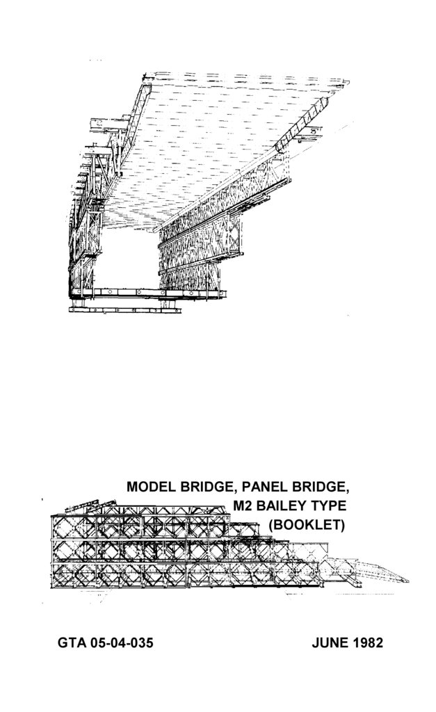
MODEL BRIDGE, PANEL BRIDGE,M2 BAILEY TYPE
(BOOKLET)
GTA 05-04-035
JUNE 1982
2.
The proponent agency of this GTA is the US Army Engineer School. Users areinvited to send comments and suggested improvements on DA Form 2028
(Recommended Changes to Publications and Blank Forms) to Commandant, US
Army Engineer School. ATTN: ATZA-TDL, Fort Belvoir, Virginia 22060.
GTA 5-4-35
17 JUNE 1982
By Order of the Secretary of the Army:
E.C. MEYER
General, United States Army
Chief of Staff
Official:
ROBERT M. JOYCE
Brigadier General, United States Army
The Adjutant General
DISTRIBUTION:
USA Training and Audiovisual Support Centers (TASC).
❆ U.S. GOVERNMENT PRINTING OFFICE: 1988 0 - 221-842
3.
*GTA 5-4-35Headquarters
Department of the Army
Washington, DC 17 June 1982
Graphic Training Aid
No. 5-4-35
MODEL BRIDGE, PANEL BRIDGE,
M2 BAILEY TYPE (BOOKLET)
Table of Contents
Introduction ....................................
Description ......................................
Operating Instructions ...................
Chapter 1
Chapter 2
Assembling and handling precautions .........
Operation details ...................................
Erection of the model ............................
*This GTA supersedes TM 5-277K, 27 September 1948.
i
4.
Chapter 3Appendix A
Appendix B
Appendix C
Maintenance Instructions .................................. 3-1
Maintenance instruction for agency assigned kit ............... 3-1
Maintenance instructions for personnel using kit .............. 3-1
Replacement and Repair .................................................. 3-2
References .......................................................... A-1
Hints to the Instructor ........................................ B-1
Aids provided by the instructor...........................................B-1
Construction hints .............................................................B-3
Suggested Method of Instruction .....................C-1
First Period ....................................................................... C-1
Second Period ................................................................. C-9
Third period .................................................................... C-12
Variation in suggested methods ..................................... C-12
The word “he,” “him,” “his,” and “men,” when used in this publication, represent both the
masculine and feminine genders unless otherwise specifically stated.
Introduction
This GTA describes how to operate and maintain Bridge Model, Training Aid Kit, Panel
Bridge, M2 Bailey Type. To obtain the greatest instructional value from this bridge model,
refer to appendixes A, B, and C.
ii
Conference
Refer to First Period Suggestions for Conference.
Practical work
Students are divided into crews (use table IV-2, chapter 4, TM 5-277, as a guide) and
moved to bridge-erection site. Have students lay out rollers, and assemble and launch
the double-double (DD) bridge. After double-double (DD) bridge is in position, convert
four bays to double-triple (DT) construction.
Hold a critique and have students disassemble bridge and replace equipment in chests.
If possible, assign students to a different crew or job for disassembly.
Variations in suggested methods
The above suggested methods of procedure can be varied to suit the size for the class
and the degree of student familiarity with Bailey bridge equipment. Additional
instruction can be provided with the model in the construction of several of the special
types of structures covered in TM 5-277, and in the destruction of completed bridges
and stockpiled equipment as described in chapter 25, TM 5-277.
C-15
5.
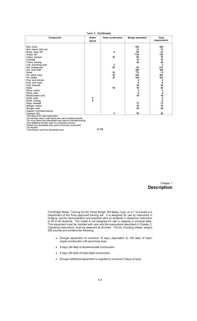
Table 5. Continued.Component
Bolt, chord
Bolt, riband (with nut)
Brace, sway, M2
Chess, M2
Clamp, transom
Footwalk
Frame, bracing
Link, launching nose
Nut, bracing bolt
Nut, chord belt
Panel
Pin, panel, long
Pin, safety
Post, end, female
Post, end, male
Post, footwalk
Raker
Ramp, button
Ramp, plain
Riband (steel curb)
Roller, plain
Roller, rocking
Rope, footwalk
Stringer, button
Stringer, plain
Support, overhead bracing
Transom, M2
Roller
layout
Nose construction
8
10
2
20
10
18
18
10
Bridge assembly1
Total
requirements
104
72
22
118
70
14
40
2
212
104
72
162
162
4
4
30
26
4
8
18
6
6
6
()
14
28
104
72
3
20
4
118
60
14
40
92
104
5
72
144
144
4
4
30
16
4
8
18
6
6
6
()
14
28
5
1
Five bays of SS nose construction.
2
Six bearings used in roller layout also used in bridge assembly.
3
Six sway braces from dismantled nose used for overhead bracing.
4
One additional member used on construction transom.
5
Panels from dismantled nose used in third-story construction.
6
As required.
7
One transom used from dismantled nose.
7
16
20
C-14
Chapter 1
Description
The Bridge Model, Training Aid Kit, Panel Bridge, M2 Bailey Type, on a 1 to 8 scale is a
Department of the Army approved training aid. It is designed for use by instructors in
bridging, and for demonstration and practical work by students in classroom instruction
of 30 to 40 students. The model is not designed for use in capacity or physical tests.
This equipment must be handled with care and the precautions described in Chapter 2,
Operating Instructions, must be observed at all times. The kit, including chests, weighs
300 pounds and contains the following.
Enough equipment to construct 10 bays (equivalent to 100 feet) of triplesingle construction with launching nose.
9 bays (90 feet) of double-double construction.
6 bays (60 feet) of triple-triple construction.
Enough additional equipment is supplied to construct 2 bays of ramp.
1-1
6.
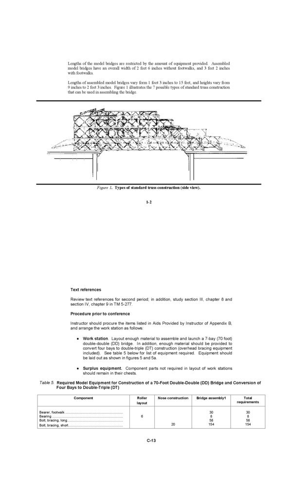
Lengths of the model bridges are restricted by the amount of equipment provided. Assembledmodel bridges have an overall width of 2 feet 6 inches without footwalks, and 3 feet 2 inches
with footwalks.
Lengths of assembled model bridges vary form 1 foot 3 inches to 15 feet, and heights vary from
9 inches to 2 feet 3 inches. Figure 1 illustrates the 7 possible types of standard truss construction
that can be used in assembling the bridge.
Figure 1. Types of standard truss construction (side view).
1-2
Text references
Review text references for second period; in addition, study section III, chapter 8 and
section IV, chapter 9 in TM 5-277.
Procedure prior to conference
Instructor should procure the items listed in Aids Provided by Instructor of Appendix B,
and arrange the work station as follows:
Work station. Layout enough material to assemble and launch a 7-bay (70 foot)
double-double (DD) bridge. In addition, enough material should be provided to
convert four bays to double-triple (DT) construction (overhead bracing equipment
included). See table 5 below for list of equipment required. Equipment should
be laid out as shown in figures 5 and 5a.
Surplus equipment. Component parts not required in layout of work stations
should remain in their chests.
Table 5. Required Model Equipment for Construction of a 70-Foot Double-Double (DD) Bridge and Conversion of
Four Bays to Double-Triple (DT)
Component
Bearer, footwalk ..........................................................
Bearing .......................................................................
Bolt, bracing, long........................................................
Bolt, bracing, short.......................................................
Roller
layout
Nose construction
Bridge assembly1
Total
requirements
20
30
8
58
154
30
8
58
154
6
C-13
7.
Table 4. Continued.Component
Roller
layout
Riband.........................................................................
Roller, plain .................................................................
Roller, rocking .............................................................
Rope, footwear ............................................................
Stringer, button............................................................
Stringer, plain ..............................................................
Transom......................................................................
Nose construction
6
6
Bridge assembly1
Total
requirements
20
20
6
6
5
()
16
32
22
5
5
()
16
32
6
18
1
Six bearings used in roller layout also used in bridge assembly.
One additional member included for use on construction transom.
3
Panels from dismantled nose used in adding second story to bridge.
4
Assuming 4 interior bays converted to double story. Use 20 short panel pins if double-story conversion starts over either end bay.
5
As required.
6
One transom utilized from dismantled nose.
2
Third period
Divide the 3-hour period of instruction into two parts: the first 30 minutes for conference,
the remaining 2 hours and 30 minutes for practical work.
Scope of instruction
Instruction includes erection of a double-double (DD) bridge and conversion of several
spans to double-triple (DT) construction. Triple-story construction is desirable in order
to illustrate use of overhead bracing.
C-12
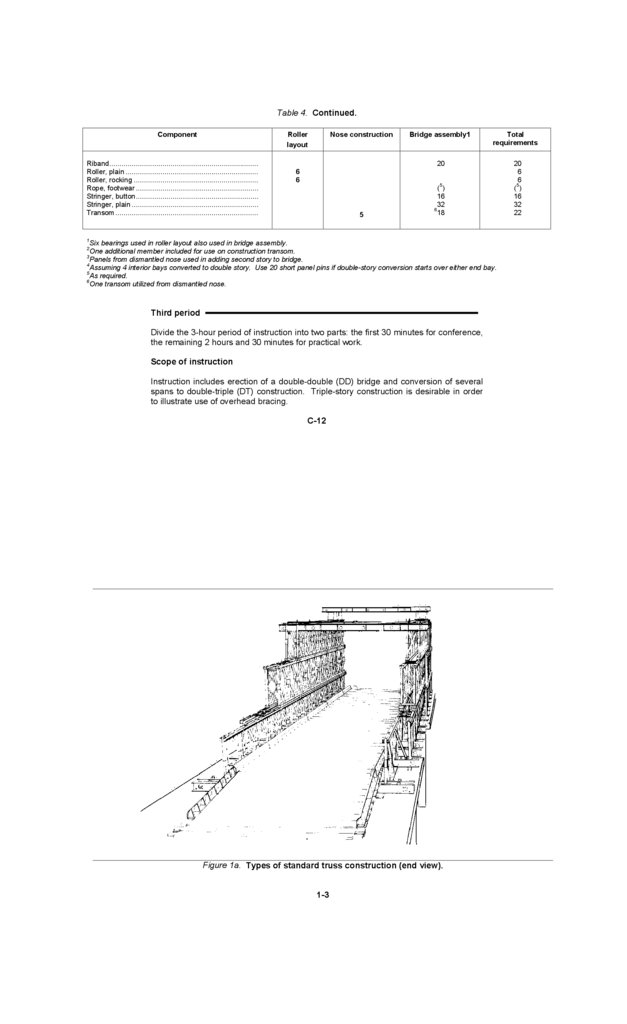
Figure 1a. Types of standard truss construction (end view).
1-3
8.
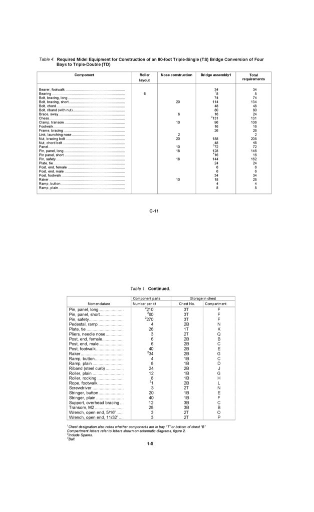
Table 4. Required Midel Equipment for Construction of an 80-foot Triple-Single (TS) Bridge Conversion of FourBays to Triple-Double (TD)
Component
Bearer, footwalk ..........................................................
Bearing .......................................................................
Bolt, bracing, long........................................................
Bolt, bracing, short.......................................................
Bolt, chord...................................................................
Bolt, riband (with nut)...................................................
Brace, sway.................................................................
Chess..........................................................................
Clamp, transom ...........................................................
Footwalk......................................................................
Frame, bracing ............................................................
Link, launching nose....................................................
Nut, bracing bolt ..........................................................
Nut, chord belt .............................................................
Panel...........................................................................
Pin, panel, long............................................................
Pin panel, short ...........................................................
Pin, safety ...................................................................
Plate, tie ......................................................................
Post, end, female ........................................................
Post, end, male ...........................................................
Post, footwalk..............................................................
Raker ..........................................................................
Ramp, button...............................................................
Ramp, plain .................................................................
Roller
layout
Nose construction
Bridge assembly1
34
1
8
74
114
48
80
16
2
131
96
16
26
6
20
8
10
2
20
188
48
3
72
128
4
16
144
24
6
6
34
18
4
8
10
18
18
10
C-11
Table 1. Continued.
Nomenclature
Pin, panel, long.....................
Pin, panel, short....................
Pin, safety.............................
Pedestal, ramp .....................
Plate, tie ...............................
Pliers, needle nose ...............
Post, end, female..................
Post, end, male.....................
Post, footwalk .......................
Raker....................................
Ramp, button ........................
Ramp, plain ..........................
Riband (steel curb) ...............
Roller, plain ..........................
Roller, rocking ......................
Rope, footwalk......................
Screwdriver ..........................
Stringer, button .....................
Stringer, plain .......................
Support, overhead bracing ...
Transom, M2 ........................
Wrench, open end, 5/16” ......
Wrench, open end, 11/32” ....
Component parts
Number per kit
2
210
2
60
2
270
4
26
3
6
6
40
2
34
4
8
24
12
8
3
1
3
20
40
12
28
3
3
1
Storage in chest
Chest No.
Compartment
3T
3T
3T
2B
1T
2T
2B
2B
2B
2B
1B
1B
2B
1B
1B
2B
2T
1B
1B
3B
3B
2T
2T
Chest designation also notes whether components are in tray “T” or bottom of chest “B”
Compartment letters refer to letters shown on schematic diagrams, figure 2.
2
Include Spares.
3
Ball.
1-5
F
F
F
N
K
Q
B
C
E
G
C
D
J
G
H
L
N
E
F
C
B
O
P
Total
requirements
34
8
74
134
48
80
24
131
106
16
26
2
208
48
72
146
16
162
24
6
6
34
28
4
8
9.
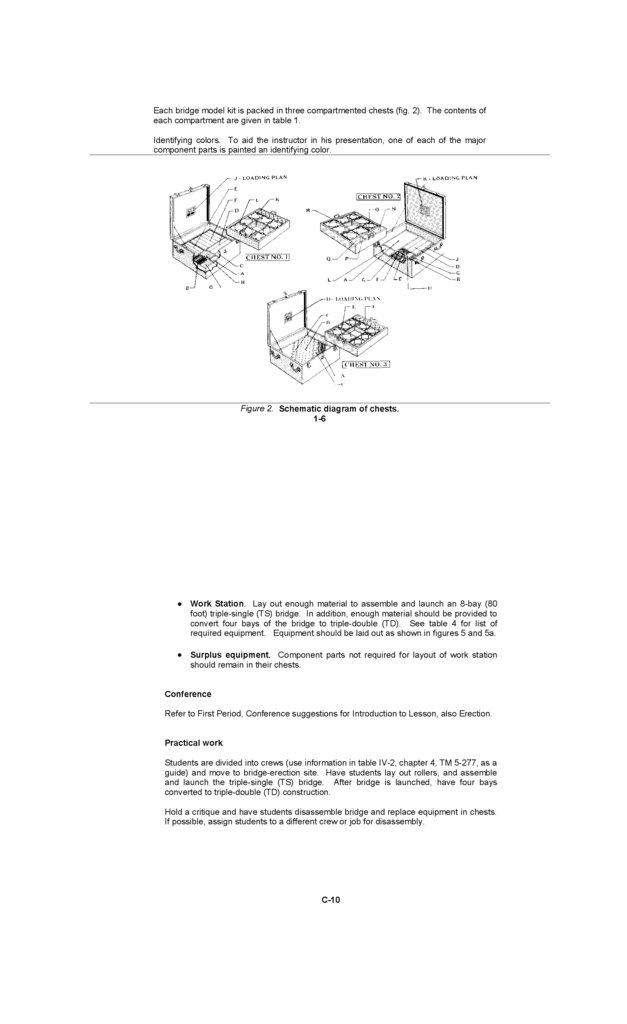
Each bridge model kit is packed in three compartmented chests (fig. 2). The contents ofeach compartment are given in table 1.
Identifying colors. To aid the instructor in his presentation, one of each of the major
component parts is painted an identifying color.
Figure 2. Schematic diagram of chests.
1-6
Work Station. Lay out enough material to assemble and launch an 8-bay (80
foot) triple-single (TS) bridge. In addition, enough material should be provided to
convert four bays of the bridge to triple-double (TD). See table 4 for list of
required equipment. Equipment should be laid out as shown in figures 5 and 5a.
Surplus equipment. Component parts not required for layout of work station
should remain in their chests.
Conference
Refer to First Period, Conference suggestions for Introduction to Lesson, also Erection.
Practical work
Students are divided into crews (use information in table IV-2, chapter 4, TM 5-277, as a
guide) and move to bridge-erection site. Have students lay out rollers, and assemble
and launch the triple-single (TS) bridge. After bridge is launched, have four bays
converted to triple-double (TD) construction.
Hold a critique and have students disassemble bridge and replace equipment in chests.
If possible, assign students to a different crew or job for disassembly.
C-10
10.
When each group has completed its work, hold a critique and have studentsdisassemble the bridge and replace equipment in chests. If possible, assign students to
a different crew or job for disassembly.
Second Period
Divide the 3-hour period of instruction into two parts: the first 20 minutes for conference
(review), the remaining 2 hours and 40 minutes for practical work.
Scope of instruction
Instruction should cover erection of a triple-single (TS) bridge and conversion of several
bays to triple-double (TD) construction.
Text references
Review text assignment in TM 5-277 for first period of instruction; in addition, study
sections III of chapter 7 and IV of chapter 8.
Procedure prior to conference
The instructor should procure the items described in Aids Provided by Instructor of
Appendix B. Arrange the student work stations as follows:
C-9
Chapter 2
Operating Instructions
The bridge model kit can be used for instruction in all phases of M2 Bailey bridge
construction. It can also be used for instruction in demolition of the equipment, both in
place and stockpiled. A suggested method of instruction for bridge construction is given
in Appendix C.
Assembling and handling precautions
To avoid damage to the bridge model kit, the following precautions must be observed in
assembling and handling this equipment.
The miniature bridge parts are very serviceable for their intended use, but
may be damaged by rough handling or abuse. These parts are made of
aluminum, wood, or flexible plastic. Handle, assemble, and disassemble the
parts carefully and replace them in their proper compartments in the chest.
All fabricated parts are manufactured with appropriate tolerances for simple,
easy assembly. Use fasteners, pins, bolts, and clamps for their intended
purposes only. In assembly, align holes correctly so that they do not require
forcing. Do NOT under any circumstances, drive the pins, bolts, or clamps
into the holes.
2-1
11.
Riband bolts are relatively weak. If a wrench is used, do NOT exert pressurewhen tightening.
DO NOT APPLY TEST LOADS TO THE BRIDGE. Load tests applied to
assembled model bridges may damage members and connectors.
When removing and replacing parts in the chest, do so gently. Proper
placement of parts in the trays, and trays in the chests, permits easy fitting
and closing. Under no circumstances are the chest lids to be forced closed.
Operation details
The Bridge Model Kit, Training Aid, Panel Bridge, M2 Bailey Type is primarily to be used
for instruction on the basic assembly of the bridge. It may also be useful for illustrating
the engineer missions in an overall operation requiring any one form of assembly of the
bridge components. Appendix C describes and illustrates assemblies which may be
demonstrated with this bridge kit.
In considering how to make use of the model, so that the class will obtain the greatest
instructional value from it, the following factors should be kept in mind:
Specific subject matter of the lecture.
Number of students.
2-2
Nomenclature. Using the colored components of the model, question or lecture students on nomenclature. If
students are to be lectured on nomenclature, chapter 2, TM-5-277, should be used to provide a close-up view of
individual parts.
Erection. Explain construction steps outlined in pertinent section of TM 5-277. Adapt procedure for roller
layout to the model by using
blocks and tape as indicated in figure 5. Normally, equipment used in the
model nose construction will have to be incorporated into the bridge proper, which requires launching as
assembly progresses. Sag in launching the model is proportionately less than sag in the bridge proper.
However, in calculating the number of launching links, assume that sag is proportionate to the bridge proper.
Practical work
Divide students into two groups and have them assemble at their assigned work stations. At each
station, divide students into crews, using table IV-2, chapter 4, TM 5-277, as a guide. At each
station, have students lay out the rollers, and assemble and launch the bridge specific for their
station. Crews shown in the above table that are not required for model erection should not be
provided.
C-8
12.
ComponentRiband.........................................................................
Roller, plain .................................................................
Roller, rocking .............................................................
Rope, footwear ............................................................
Stringer, button............................................................
Stringer, plain ..............................................................
Transom......................................................................
Roller
layout
Nose construction
3
5
6
2
Bridge assembly1
Total
requirements
12
12
6
2
6
()
10
20
14
6
()
10
20
7
12
1
One 10-foot ramp on end only. Footwalk on one side only.
Requirements reduced by 50 percent because of shortage of equipment. Bearings used in roller layout also used in bridge assembly.
3
Requirement reduced by 2 because of limited number available. Bridge can be assembled and launched with a total of 12.
4
One additional member used on construction transom.
5
Construction rollers (near blank) also used on far bank as landing rollers.
6
As required.
7
One transom used form dismantled nose.
2
Conference
Introduction to lesson. Point out that erection of this model is typical of actual
field erection of the bridge. In field construction, many variations in length,
launching difficulties, and types of structures occur. The capacities of various
types of bridges, traffic control, and maintenance procedures must also be
included in this introduction.
C-7
Working space available.
Time allotted.
Number of participating instructors.
Available training films and film strips.
Reference materials.
The instructor should carefully organize the period of instruction, using the hints in
Appendix B and adopting a procedure of instruction similar to that outlined in Appendix
C. Realistic simulated bridge sites, proper division of students into working groups, and
facilities for group work stations will do much to insure the success of the instruction.
This requires careful preplanning. TM 5-277 (Bailey Bridge) will be a valuable guide for
the class in adapting the model erection procedures to the actual full-size Bailey bridge
equipment. The instructors must be entirely familiar with TM-5-277 to enable them to
compare each component of the model to the corresponding full-scale bridge
component.
Erection of the model
The instructor must adapt the model kit to best illustrate a given course of instruction. In
general, the step-by-step procedures should be the same as those used in assembly of
the actual bridge. The instructor will use the following outline as a guide to his
presentation:
2-3
13.
Preparatory informationSite and approach problems.
Factors affecting type, method, and direction of assembly.
Types of approaches and development of shore connections.
Type of span suited to specific conditions.
Appropriate use of film, film strips, and references.
Demolition measures.
Erection procedures
Description of model to be assembled for a specific lecture.
Direct comparison to actual bridge.
Description of individual parts and their nomenclature.
Pertinent review of TM 5-277.
Standard methods of assembly.
2-4
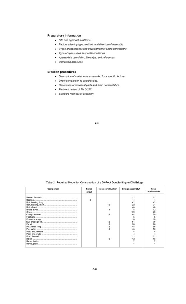
Table 3. Required Model for Construction of a 50-Foot Double-Single (DS) Bridge
Component
Bearer, footwalk ..........................................................
Bearing .......................................................................
Bolt, bracing, long........................................................
Bolt, bracing, short.......................................................
Bolt, riband .................................................................
Brace, sway.................................................................
Chess..........................................................................
Clamp, transom ...........................................................
Footwalk......................................................................
Frame, bracing ............................................................
Nut, bracing bolt ..........................................................
Panel...........................................................................
Pin, panel, long............................................................
Pin, safety ...................................................................
Post, end, female ........................................................
Post, end, male ...........................................................
Post, footwalk..............................................................
Raker ..........................................................................
Ramp, button...............................................................
Ramp, plain .................................................................
Roller
layout
Nose construction
2
12
4
6
12
6
8
8
6
C-6
Bridge assembly1
11
2
4
42
22
48
3
8
4
79
44
5
10
64
20
48
48
4
4
11
12
2
4
Total
requirements
11
4
42
34
48
12
79
50
5
10
76
26
56
56
4
4
11
18
2
4
14.
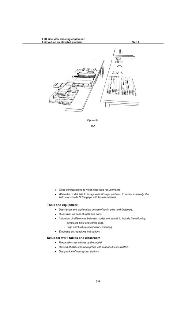
Left side view showing equipmentLaid out on an elevated platform.
Step 2.
Figure 5a.
C-5
Truss configurations to meet class load requirements.
When the model fails to incorporate all steps pertinent to actual assembly, the
instructor should fill the gaps with lecture material.
Tools and equipment
Description and explanation on use of tools, pins, and fasteners.
Discussion on care of tools and parts.
Indication of differences between model and actual, to include the following:
- Simulated bolts and spring clips.
- Lugs and built-up section for simulating.
Emphasis on repacking instructions.
Setup for work tables and classroom
Preparations for setting up the model.
Division of class into work group with responsible instructors.
Designation of work group stations.
2-5
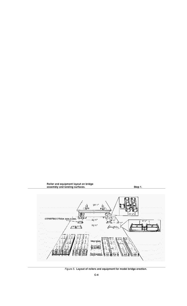
15.
Roller and equipment layout on bridgeassembly and landing surfaces.
Step 1.
Figure 5. Layout of rollers and equipment for model bridge erection.
C-4
16.
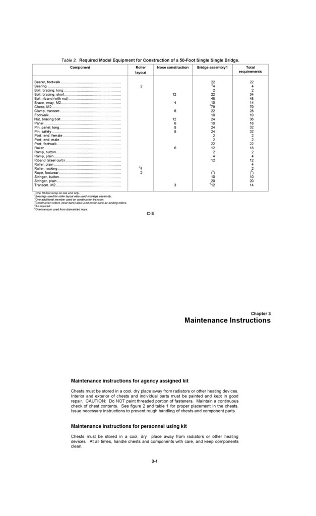
Table 2. Required Model Equipment for Construction of a 50-Foot Single Single Bridge.Component
Bearer, footwalk ..........................................................
Bearing .......................................................................
Bolt, bracing, long........................................................
Bolt, bracing, short.......................................................
Bolt, riband (with nut)...................................................
Brace, sway, M2..........................................................
Chess, M2 ...................................................................
Clamp, transom ...........................................................
Footwalk......................................................................
Nut, bracing bolt ..........................................................
Panel...........................................................................
Pin, panel, long............................................................
Pin, safety ...................................................................
Post, end, female ........................................................
Post, end, male ...........................................................
Post, footwalk..............................................................
Raker ..........................................................................
Ramp, button...............................................................
Ramp, plain .................................................................
Riband (steel curb) ......................................................
Roller, plain .................................................................
Roller, rocking .............................................................
Rope, footwear ............................................................
Stringer, button............................................................
Stringer, plain ..............................................................
Transom, M2 ...............................................................
Roller
layout
Nose construction
2
12
4
6
12
6
8
8
6
4
4
2
Bridge assembly1
Total
requirements
22
2
4
2
22
48
10
3
79
22
10
24
10
24
24
2
2
22
12
2
4
12
22
4
2
34
48
14
79
28
10
36
16
32
32
2
2
22
18
2
4
12
4
2
5
()
10
20
14
5
()
10
20
6
12
3
1
One 10-foot ramp on one end only.
Bearings used for roller layout also used in bridge assembly.
One additional member used on construction transom.
4
Construction rollers (near-bank) also used on far bank as landing rollers.
5
As required.
6
One transom used from dismantled nose.
2
3
C-3
Chapter 3
Maintenance Instructions
Maintenance instructions for agency assigned kit
Chests must be stored in a cool, dry place away from radiators or other heating devices.
Interior and exterior of chests and individual parts must be painted and kept in good
repair. CAUTION: Do NOT paint threaded portion of fasteners. Maintain a continuous
check of chest contents. See figure 2 and table 1 for proper placement in the chests.
Issue necessary instructions to prevent rough handling of chests and component parts.
Maintenance instructions for personnel using kit
Chests must be stored in a cool, dry place away from radiators or other heating
devices. At all times, handle chests and components with care, and keep components
clean.
3-1
17.
After use, see that all items are replaced in proper compartments as shown on thecharts inside the lid of each chest. Be especially careful with tools and fasteners; they
are small and easily lost or misplaced.
Report any lost, damaged, or destroyed parts to the agency to whom the model is
assigned.
Replacement and repair
Replacement parts may be obtained through local TASCs.
3-2
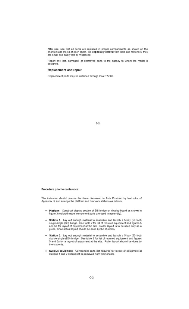
Procedure prior to conference
The instructor should procure the items discussed in Aids Provided by Instructor of
Appendix B, and arrange the platform and two work stations as follows:
Platform. Construct display section of DS bridge on display board as shown in
figure 3 (colored model component parts are used in assembly).
Station 1. Lay out enough material to assemble and launch a 5-bay (50 foot)
single-single (SS) bridge. See table 2 for list of required equipment and figures 5
and 5a for layout of equipment at the site. Roller layout is to be used only as a
guide, since actual layout should be done by the students.
Station 2. Lay out enough material to assemble and launch a 5-bay (50 foot)
double-single (DS) bridge. See table 3 for list of required equipment and figures
5 and 5a for a layout of equipment at the site. Roller layout should be done by
the students.
Surplus equipment. Component parts not required for layout of equipment at
stations 1 and 2 should not be removed from their chests.
C-2
18.
Appendix CSuggested Method Of Instruction
A suggested method of using the model kit to good advantage follows. Divide the
instruction into three periods, each at least 3 hours long. The first period should cover
nomenclature and basic construction; the second and third periods, advanced
construction.
First Period
Divide the 3-hour period of instruction into two parts: the first hour for conference; the
second and third hours for practical work.
Scope of Instruction
Instruction covers nomenclature of component parts and erection of a single-single (SS)
and double-single (DS) bridge.
Text references
TM 5-277, chapters 1,2,4,6, and 7.
C-1
Appendix A
References
1. TECHNICAL MANUALS (TM)
TM 5-210
TM 5-277
Military Floating Bridge Equipment
Bailey Bridge
2. FIELD MANUALS (FM)
FM 5-34
FM 21-6
FM 21-30
Engineer Field Data
How to Prepare and Conduct Military Training
Military Symbols
3. ADMINISTRATIVE REGULATIONS (AR)
AR 310-25
AR 310-50
Dictionary of United States Army Terms
Authorized Abbreviations and Brevity Codes
4. DEPARTMENT OF THE ARMY PAMPHLETS (DA Pams)
DA Pam 108-1
DA Pam 310-Series
DA Pam 310-12
Index of Army Motion Pictures, and Related Audi-Visual Aids
Index of Administrative Publications Series
Index and Description of Army Training Devices
A-1
19.
5. TRAINING EXTENSION COURSE LESSONS (TEC)030-051-6442-F
030-051-6443-F
030-051-6444-F
030-051-6445-F
030-051-6446-F
030-051-6447-F
030-051-6448-F
030-051-6449-F
030-051-6450-F
030-051-6451-F
030-051-6452-F
030-051-6453-F
030-051-6454-F
Introduction and Construction Crews
Double and Single Bailey Bridge Site Layout, Pt I
Double and Single Bailey Bridge Site Layout, Pt II
Double and Single Bailey Bridge Assembly Initial
Launching Nose Bay
Double and Single Bailey Bridge Assembly Bays 2
through 5 of Launching Nose
Double and Single Bailey Bridge Assembly Bridge
Bays, Pt I
Assemble Bridge Bays, Pt II
Jacking Down Near-Bank Bridge End
Jacking Down Far-Bank Bridge End
Site Layout
Bridge Assembly, Pt I
Bridge Assembly, Pt II
Bridge Assembly, Pt III
A-2
20.
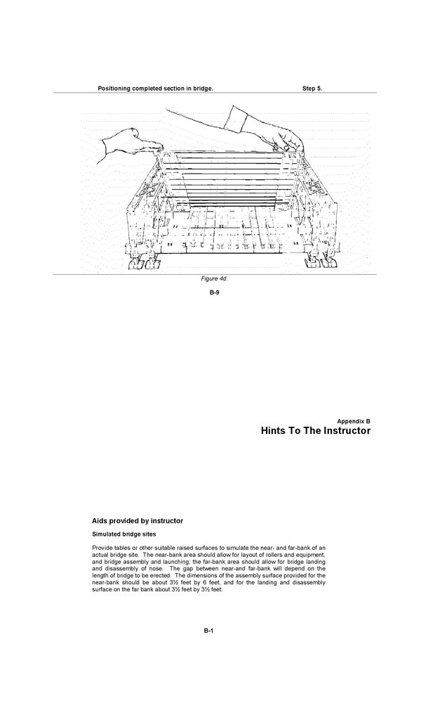
Positioning completed section in bridge.Step 5.
Figure 4d.
B-9
Appendix B
Hints To The Instructor
Aids provided by instructor
Simulated bridge sites
Provide tables or other suitable raised surfaces to simulate the near- and far-bank of an
actual bridge site. The near-bank area should allow for layout of rollers and equipment,
and bridge assembly and launching; the far-bank area should allow for bridge landing
and disassembly of nose. The gap between near-and far-bank will depend on the
length of bridge to be erected. The dimensions of the assembly surface provided for the
near-bank should be about 3½ feet by 6 feet, and for the landing and disassembly
surface on the far bank about 3½ feet by 3½ feet.
B-1
21.
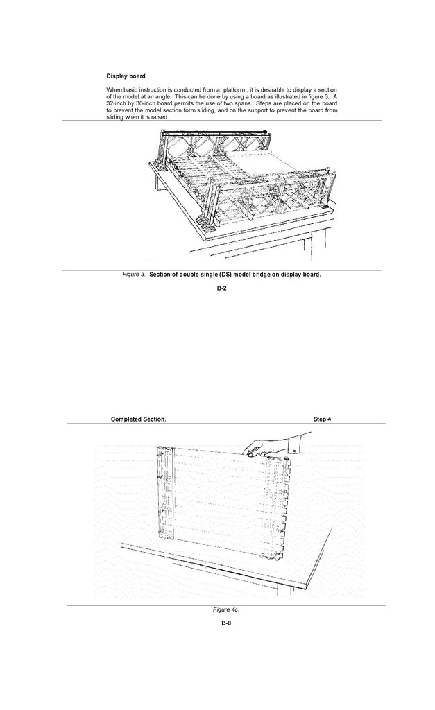
Display boardWhen basic instruction is conducted from a platform , it is desirable to display a section
of the model at an angle. This can be done by using a board as illustrated in figure 3. A
32-inch by 36-inch board permits the use of two spans. Steps are placed on the board
to prevent the model section form sliding, and on the support to prevent the board from
sliding when it is raised.
Figure 3. Section of double-single (DS) model bridge on display board.
B-2
Completed Section.
Step 4.
Figure 4c.
B-8
22.
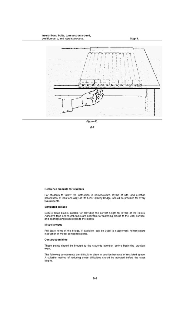
Insert riband bolts; turn section around,position curb, and repeat process.
Step 3.
Figure 4b.
B-7
Reference manuals for students
For students to follow the instruction in nomenclature, layout of site, and erection
procedures, at least one copy of TM 5-277 (Bailey Bridge) should be provided for every
two students.
Simulated grillage
Secure small blocks suitable for providing the correct height for layout of the rollers.
Adhesive tape and thumb tacks are desirable for fastening blocks to the work surface,
and bearings and plain rollers to the blocks.
Miscellaneous
Full-scale items of the bridge, if available, can be used to supplement nomenclature
instruction of model component parts.
Construction hints
These points should be brought to the students attention before beginning practical
work.
The following components are difficult to place in position because of restricted space.
A suitable method of reducing these difficulties should be adopted before the class
begins.
B-3
23.
Tie plates.Safety pins (difficult to insert on the lower pin in the outer truss of each story
of triple-truss construction).
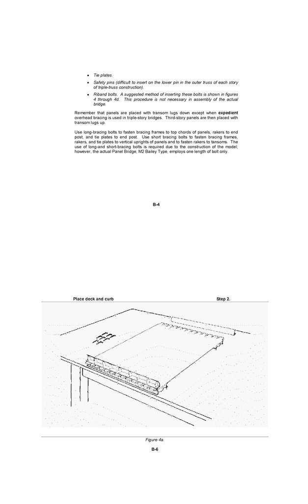
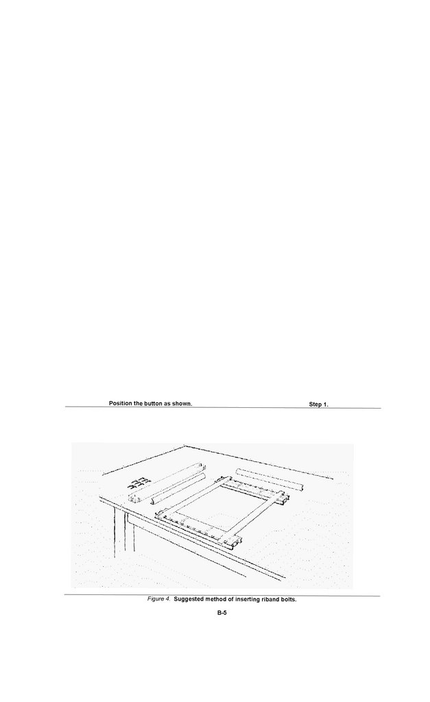
Riband bolts. A suggested method of inserting these bolts is shown in figures
4 through 4d. This procedure is not necessary in assembly of the actual
bridge.
Remember that panels are placed with transom lugs down except when expedient
overhead bracing is used in triple-story bridges. Third-story panels are then placed with
transom lugs up.
Use long-bracing bolts to fasten bracing frames to top chords of panels, rakers to end
post, and tie plates to end post. Use short bracing bolts to fasten bracing frames,
rakers, and tie plates to vertical uprights of panels and to fasten rakers to tansoms. The
use of long-and short-bracing bolts is required due to the construction of the model;
however, the actual Panel Bridge, M2 Bailey Type, employs one length of bolt only.
B-4
Place deck and curb
Step 2.
Figure 4a.
B-6
24.
Position the button as shown.Step 1.
Figure 4. Suggested method of inserting riband bolts.
B-5