


 industry
Similar presentations:


Fuel Handling Systems Licensing Documentation
1.
Hanhikivi–1 NPPFUEL HANDLING SYSTEMS
LICENSING DOCUMENTATION
at the example of Refueling
machine
Helsinki, 18th of May 2017
Speakers:
Aleksandr Kutuzov
Aleksandr Brunov
2.
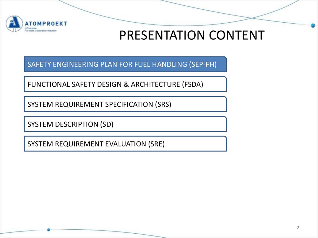
PRESENTATION CONTENTSAFETY ENGINEERING PLAN FOR FUEL HANDLING (SEP-FH)
FUNCTIONAL SAFETY DESIGN & ARCHITECTURE (FSDA)
SYSTEM REQUIREMENT SPECIFICATION (SRS)
SYSTEM DESCRIPTION (SD)
SYSTEM REQUIREMENT EVALUATION (SRE)
2
3.
SEP-FH targetsSafety Engineering Plan for Fuel Handling has been prepared to expand
plant SEP and SEQP to cover fuel handling systems. SEP-FHs targets are to:
- define the list of licensing documents for fuel handling;
- define the list of parent documents, requirements and standards
applicable for each document;
- define the tasks for each document;
- describe the principles of documents developing;
- describe the methodology for nuclear risk analysis and
functional safety design.
3
4.
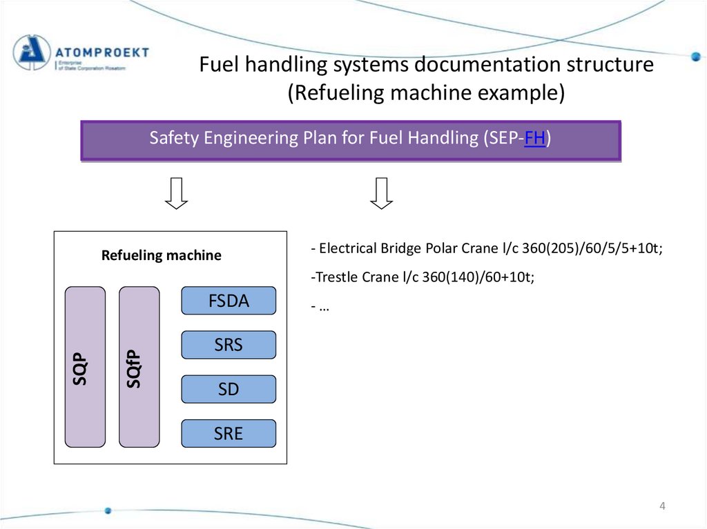
Fuel handling systems documentation structure(Refueling machine example)
Safety Engineering Plan for Fuel Handling (SEP-FH)
Refueling machine
- Electrical Bridge Polar Crane l/c 360(205)/60/5/5+10t;
-Trestle Crane l/c 360(140)/60+10t;
SQfP
SQP
FSDA
-…
SRS
SD
SRE
4
5.
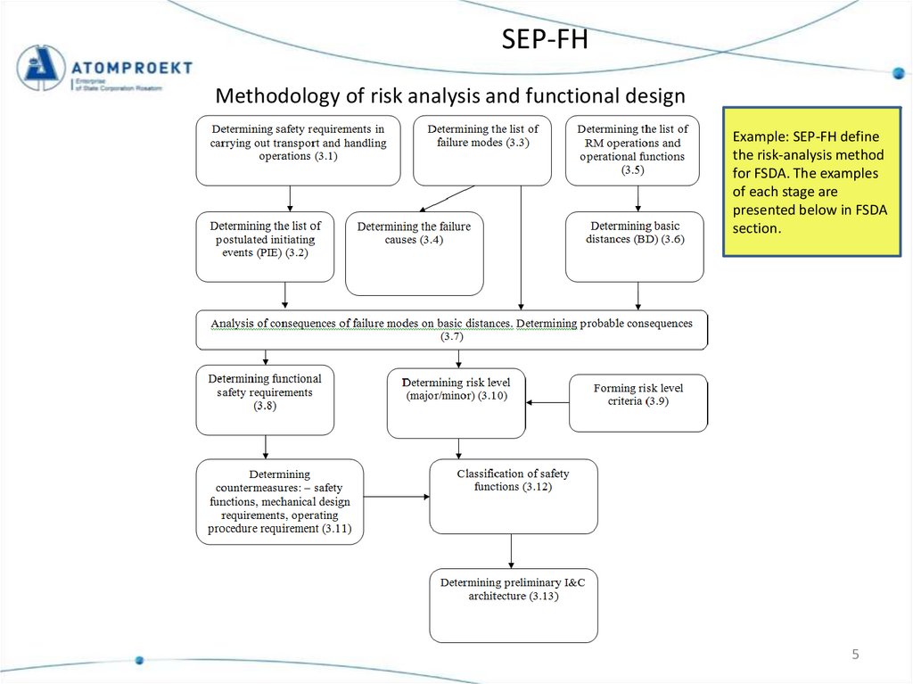
SEP-FHMethodology of risk analysis and functional design
Example: SEP-FH define
the risk-analysis method
for FSDA. The examples
of each stage are
presented below in FSDA
section.
5
6.
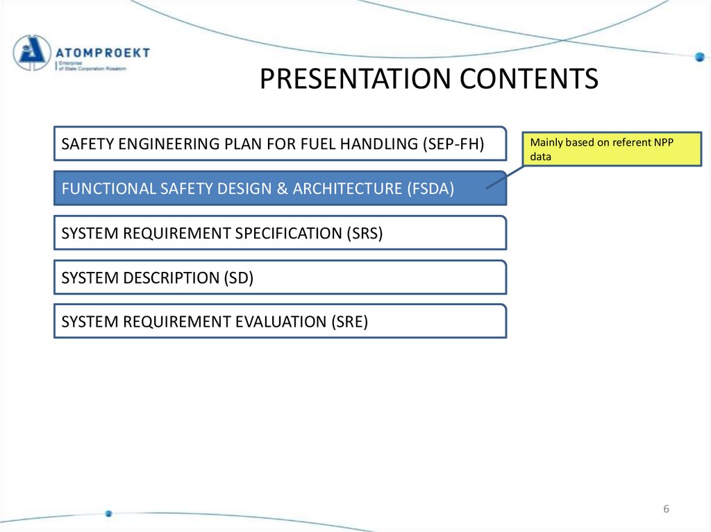
PRESENTATION CONTENTSSAFETY ENGINEERING PLAN FOR FUEL HANDLING (SEP-FH)
Mainly based on referent NPP
data
FUNCTIONAL SAFETY DESIGN & ARCHITECTURE (FSDA)
SYSTEM REQUIREMENT SPECIFICATION (SRS)
SYSTEM DESCRIPTION (SD)
SYSTEM REQUIREMENT EVALUATION (SRE)
6
7.
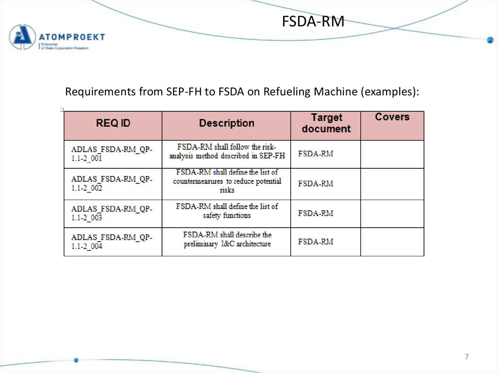
FSDA-RMRequirements from SEP-FH to FSDA on Refueling Machine (examples):
7
8.
FSDA-RMMain safety requirements for refueling machine
Main safety requirements for RM are
based on YVL and EPC requirements for
fuel handling at the NPP. The reference
NPP experience is utilized as well.
See the next page
8
9.
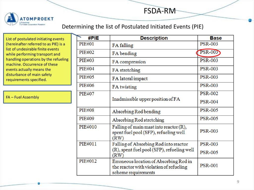
FSDA-RMDetermining the list of Postulated Initiated Events (PIE)
List of postulated initiating events
(hereinafter referred to as PIE) is a
list of undesirable finite events
while performing transport and
handling operations by the refueling
machine. Occurrence of these
events actually means the
disturbance of main safety
requirements specified.
FA – Fuel Assembly
9
10.
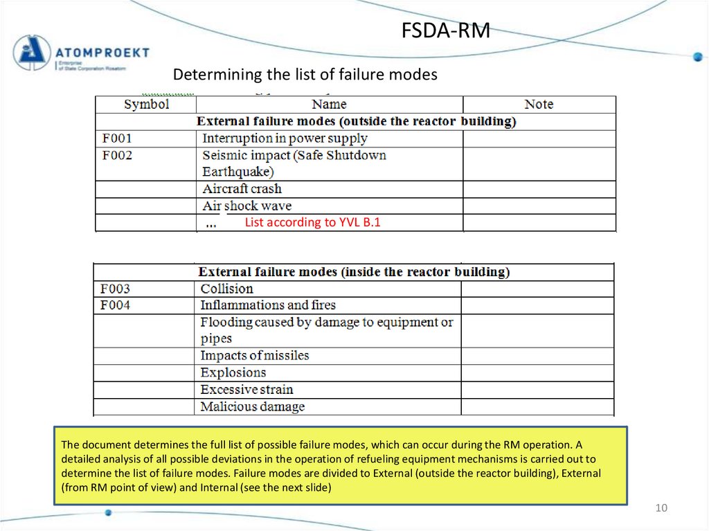
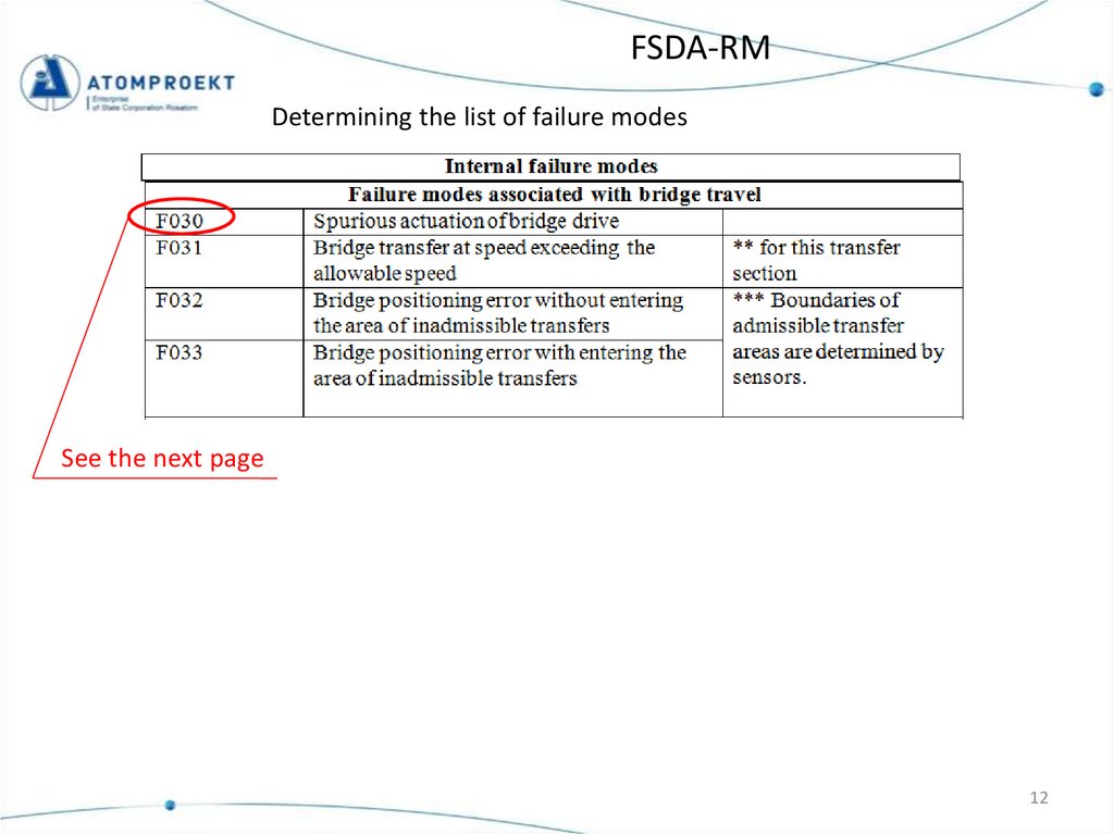
FSDA-RMDetermining the list of failure modes
List according to YVL B.1
The document determines the full list of possible failure modes, which can occur during the RM operation. A
detailed analysis of all possible deviations in the operation of refueling equipment mechanisms is carried out to
determine the list of failure modes. Failure modes are divided to External (outside the reactor building), External
(from RM point of view) and Internal (see the next slide)
10
11.
FSDA-RMDetermining the list of failure modes
All possible kinds of disturbances in operation
of RM mechanisms and devices, regardless of
their possible impact on safety of transport
and handling operations with nuclear fuel are
considered as internal failure modes of the
refueling machine.
See the next page
Internal failure modes
Destruction of the RM
mechanisms and
assemblies
Failure modes
associated with bridge
travel
Failure modes
associated with trolley
transfer
Failure modes
associated with travel
of FA gripper
Failure modes
associated with the
main mast sweep
Failure modes
associated with lock
travel
Failure modes
associated with
Control Rod gripper
travel
Failure modes
associated with travel
of FA lift-off
mechanism
Failure modes
associated with
placing Control Rods in
the reactor
11
12.
FSDA-RMDetermining the list of failure modes
See the next page
12
13.
FSDA-RMDetermining the failure causes
The preliminary list of failure causes has been identified. In the next phase requirement
YVL-E.11-604 for FMEA will be prepared in more detail for component level by the
equipment supplier (YVL-E.11-605).
13
14.
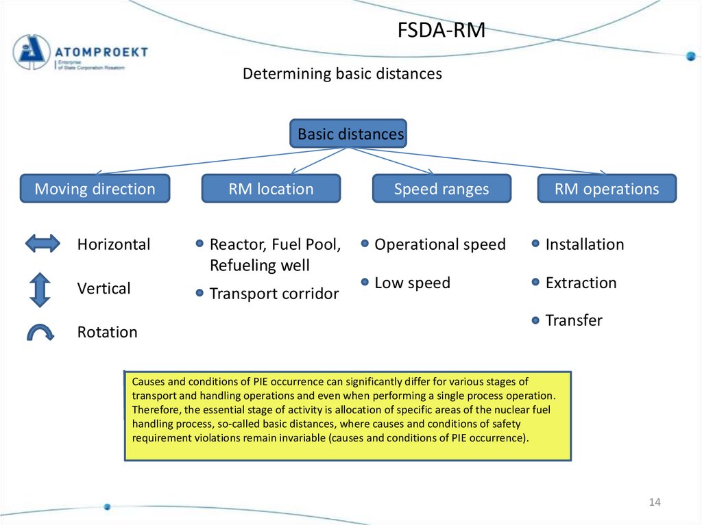
FSDA-RMDetermining basic distances
Basic distances
Moving direction
RM location
Speed ranges
Horizontal
Reactor, Fuel Pool,
Refueling well
Operational speed
Installation
Vertical
Transport corridor
Low speed
Extraction
Rotation
RM operations
Transfer
Causes and conditions of PIE occurrence can significantly differ for various stages of
transport and handling operations and even when performing a single process operation.
Therefore, the essential stage of activity is allocation of specific areas of the nuclear fuel
handling process, so-called basic distances, where causes and conditions of safety
requirement violations remain invariable (causes and conditions of PIE occurrence).
14
15.
FSDA-RMDetermining basic distances
Basic distances in case of horizontal movements of RM
BD 10 – RM with FA or absorbing rod of the control and protection system (CPS AR)
(BD12) – RM without FA, CPS AR
15
16.
FSDA-RMDetermining basic distances
Basic distances in case of vertical movements for the FA transfer operations.
Diagram shows the general approach to
define basic intervals in case of vertical
movements. If there is a difference
between movements in Reactor and
Fuel Pool or Refueling well (from
consequences point of view), special
basic intervals are defined. Otherwise
basic intervals are the same.
16
17.
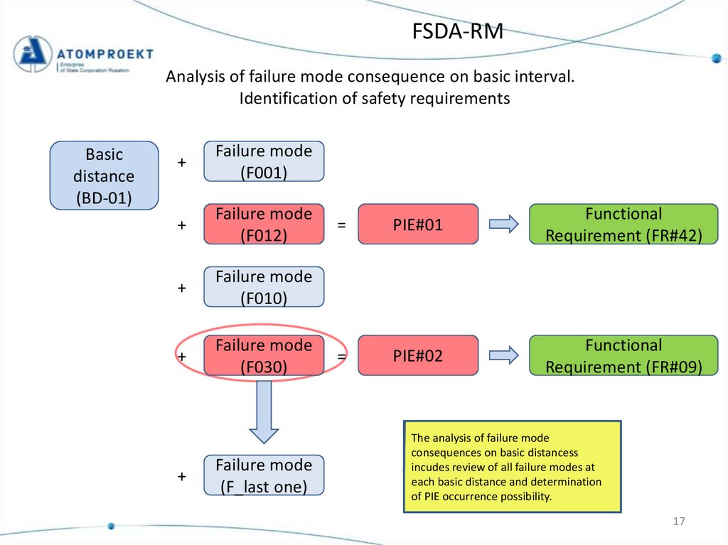
FSDA-RMAnalysis of failure mode consequence on basic interval.
Identification of safety requirements
Basic
distance
(BD-01)
+
Failure mode
(F001)
+
Failure mode
(F012)
+
Failure mode
(F010)
+
Failure mode
(F030)
+
Failure mode
(F_last one)
=
PIE#01
Functional
Requirement (FR#42)
=
PIE#02
Functional
Requirement (FR#09)
The analysis of failure mode
consequences on basic distancess
incudes review of all failure modes at
each basic distance and determination
of PIE occurrence possibility.
17
18.
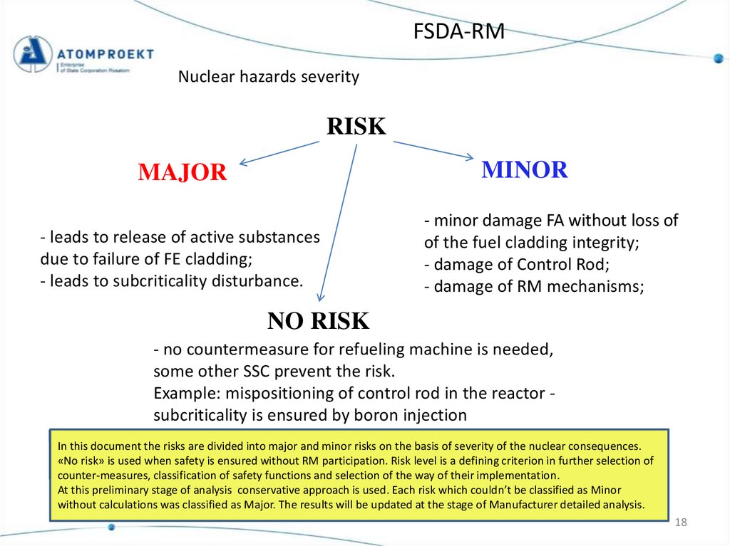
FSDA-RMNuclear hazards severity
RISK
MINOR
MAJOR
- leads to release of active substances
due to failure of FE cladding;
- leads to subcriticality disturbance.
- minor damage FA without loss of
of the fuel cladding integrity;
- damage of Control Rod;
- damage of RM mechanisms;
NO RISK
- no countermeasure for refueling machine is needed,
some other SSC prevent the risk.
Example: mispositioning of control rod in the reactor subcriticality is ensured by boron injection
In this document the risks are divided into major and minor risks on the basis of severity of the nuclear consequences.
«No risk» is used when safety is ensured without RM participation. Risk level is a defining criterion in further selection of
counter-measures, classification of safety functions and selection of the way of their implementation.
At this preliminary stage of analysis conservative approach is used. Each risk which couldn’t be classified as Minor
without calculations was classified as Major. The results will be updated at the stage of Manufacturer detailed analysis.
18
19.
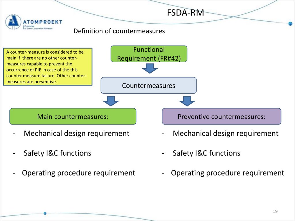
FSDA-RMDefinition of countermeasures
A counter-measure is considered to be
main if there are no other countermeasures capable to prevent the
occurrence of PIE in case of the this
counter measure failure. Other countermeasures are preventive.
Functional
Requirement (FR#42)
Countermeasures
Main countermeasures:
Preventive countermeasures:
-
Mechanical design requirement
-
Mechanical design requirement
-
Safety I&C functions
-
Safety I&C functions
- Operating procedure requirement
- Operating procedure requirement
19
20.
FSDA-RMRisk analysis example
9.1.5.7 Refueling machine. Functional Safety Design and Architecture (FSDA).
Appendix 1 – Risk analysis table
20
21.
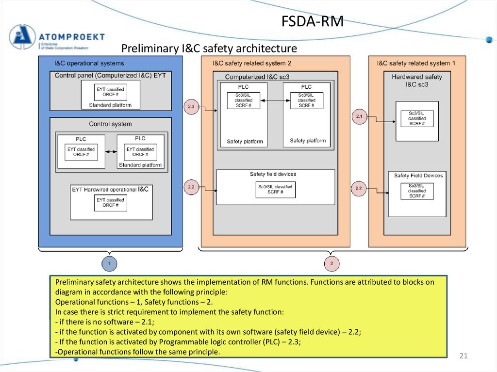
FSDA-RMPreliminary I&C safety architecture
Preliminary safety architecture shows the implementation of RM functions. Functions are attributed to blocks on
diagram in accordance with the following principle:
Operational functions – 1, Safety functions – 2.
In case there is strict requirement to implement the safety function:
- if there is no software – 2.1;
- if the function is activated by component with its own software (safety field device) – 2.2;
- If the function is activated by Programmable logic controller (PLC) – 2.3;
-Operational functions follow the same principle.
21
22.
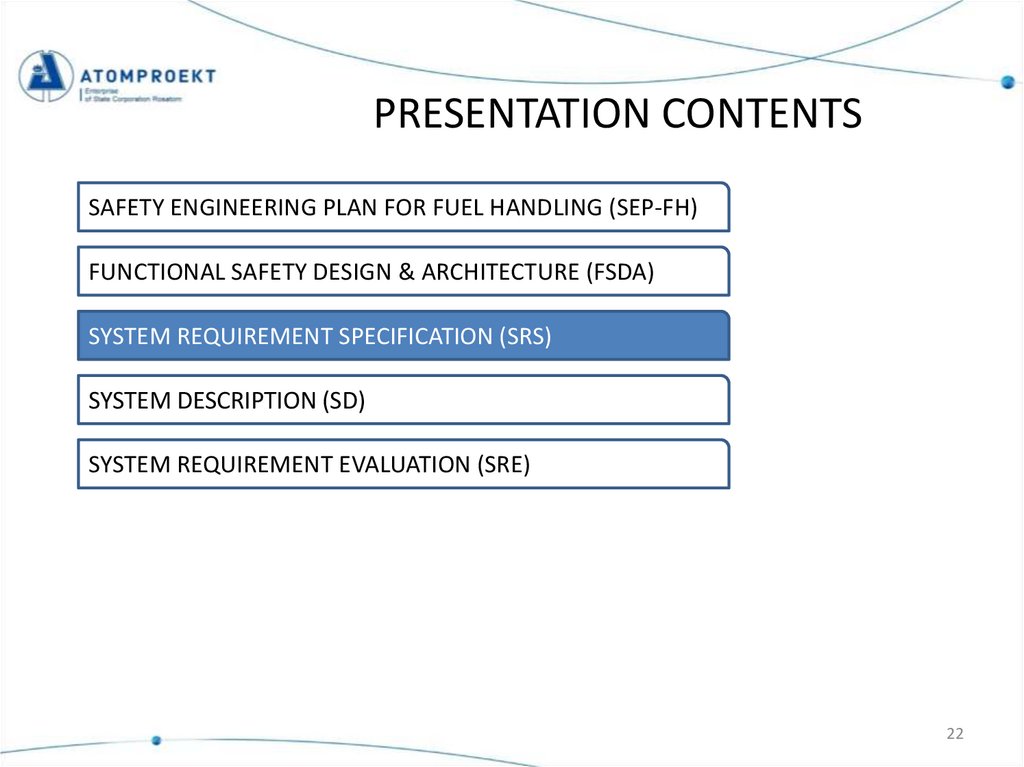
PRESENTATION CONTENTSSAFETY ENGINEERING PLAN FOR FUEL HANDLING (SEP-FH)
FUNCTIONAL SAFETY DESIGN & ARCHITECTURE (FSDA)
SYSTEM REQUIREMENT SPECIFICATION (SRS)
SYSTEM DESCRIPTION (SD)
SYSTEM REQUIREMENT EVALUATION (SRE)
22
23.
System Requirement SpecificationThe purpose of this document is to present all the requirements related to the
Refueling Machine (RM) from YVL-guides, EPC-contract, Upper level documents and other
sources.
Moreover, this document elaborates further requirements and provides traceability
of the requirements.
YVLguides
EPCcontract
Upper
level
Other
SRS
According to YVL E.11-5.1-517 safety functions that
have been identified on the basis of the hoisting
device unit’s risk analysis (FSDA) shall be focused
on the hoisting device unit’s subsystems as
functional requirements (SRS).
Example:
23
24.
PRESENTATION CONTENTSSAFETY ENGINEERING PLAN FOR FUEL HANDLING (SEP-FH)
FUNCTIONAL SAFETY DESIGN & ARCHITECTURE (FSDA)
SYSTEM REQUIREMENT SPECIFICATION (SRS)
Mostly based on the reference
NPP data
SYSTEM DESCRIPTION (SD)
SYSTEM REQUIREMENT EVALUATION (SRE)
24
25.
System descriptionContents
9.1.5 Transportation and Handling Equipment of the Fuel Handling System
9.1.5.7. REFUELING MACHINE
Structure is based on KAA pilot
25
26.
System descriptionGeneral information
The RM is designed for :
- fresh and spent fuel handling;
- handling of absorbing rods of the control and protection system (hereinafter
CPS AR);
- monitoring of FA tightness;
- monitoring of FA and CPS AR reloading using video control system;
- tools handling:
- CPS AR cask;
- device for FA installation level monitoring;
- FA seats inspection device;
- FA inspection device;
- device for lifting of dropped FA and leak-tight bottle.
26
27.
System descriptionRM frontal view
9
9
Description of RM components
The refueling machine (RM) consists of a bridge (1) located in the central
hall at the elevation of +31,200, a trolley (2) on which the main operating
components of the machine are installed: the main mast (3) and TV arm
(4).
Power to electrical equipment located on RM are supplied trough the local
cabinet (7) and cable chain (5)
"Seismic terminal" for seismic clamps on the bridge is located outside the
rail track (8).
The RM is controlled from a stationary remote control room located
outside the reactor building containment. The control and monitoring
equipment is located in the control room.
4
3
3 – Main mast
4 – TV arm
9 – TV cameras
27
28.
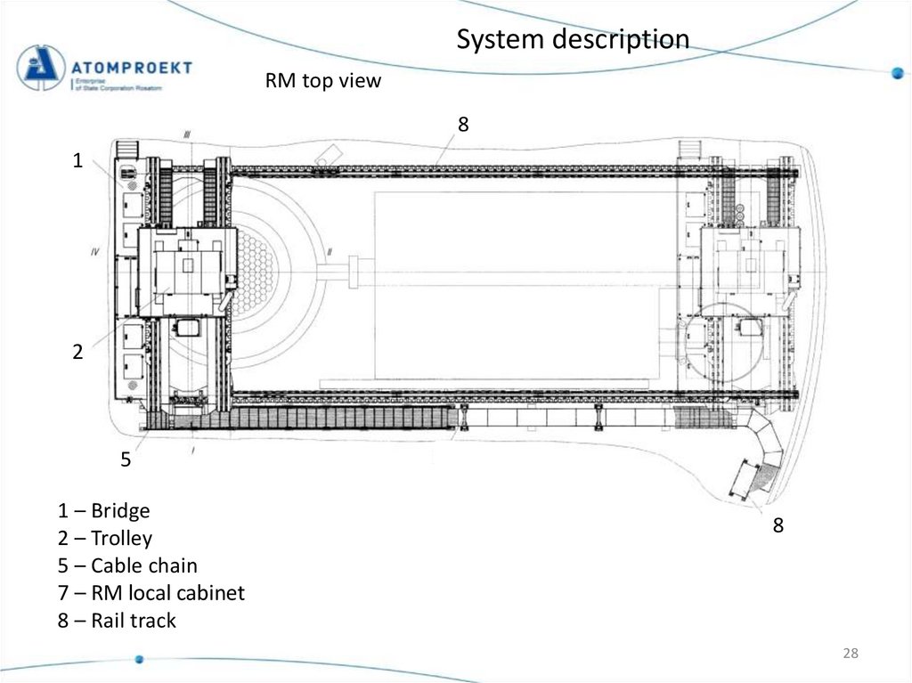
System descriptionRM top view
8
1
2
5
1 – Bridge
2 – Trolley
5 – Cable chain
7 – RM local cabinet
8 – Rail track
8
28
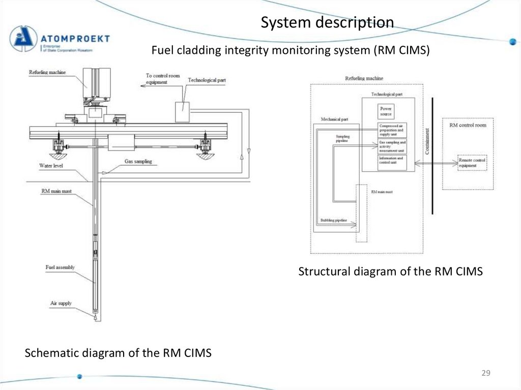
29.
System descriptionFuel cladding integrity monitoring system (RM CIMS)
Structural diagram of the RM CIMS
Schematic diagram of the RM CIMS
29
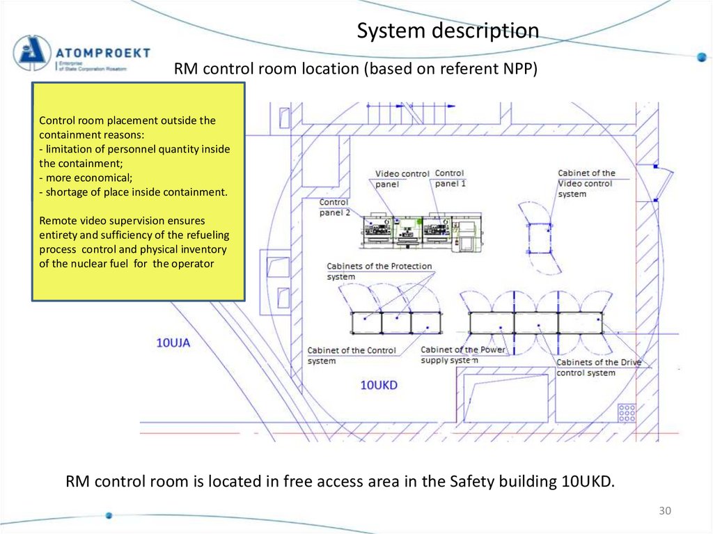
30.
System descriptionRM control room location (based on referent NPP)
Control room placement outside the
containment reasons:
- limitation of personnel quantity inside
the containment;
- more economical;
- shortage of place inside containment.
Remote video supervision ensures
entirety and sufficiency of the refueling
process control and physical inventory
of the nuclear fuel for the operator
RM control room is located in free access area in the Safety building 10UKD.
30
31.
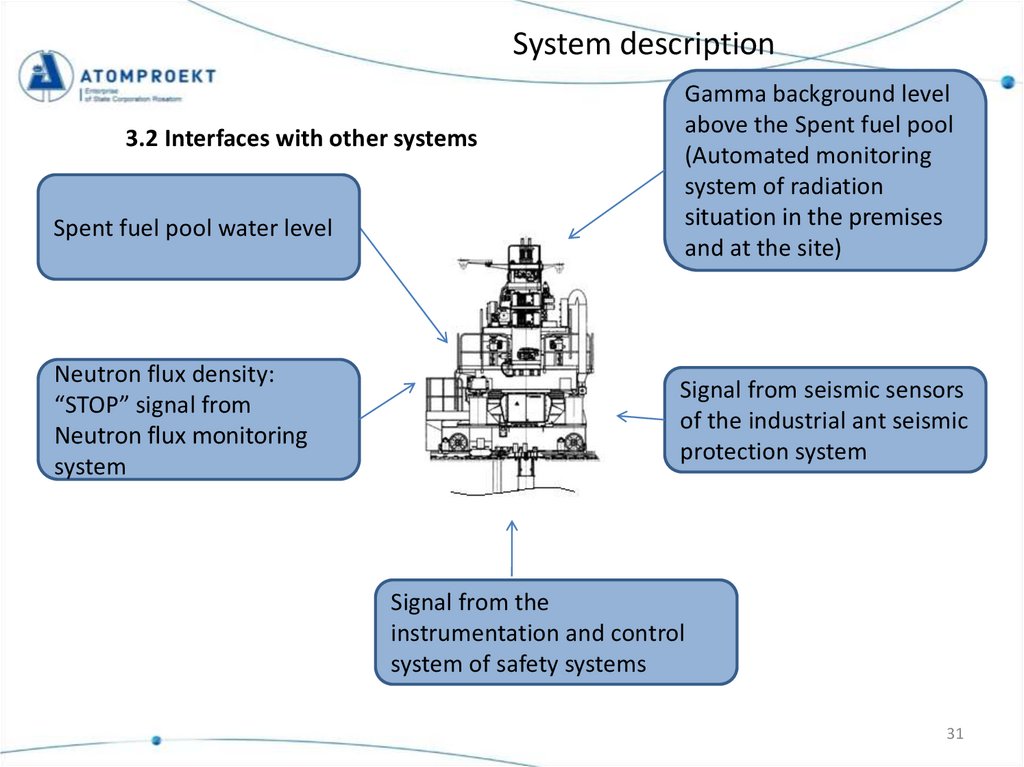
System description3.2 Interfaces with other systems
Spent fuel pool water level
Neutron flux density:
“STOP” signal from
Neutron flux monitoring
system
Gamma background level
above the Spent fuel pool
(Automated monitoring
system of radiation
situation in the premises
and at the site)
Signal from seismic sensors
of the industrial ant seismic
protection system
Signal from the
instrumentation and control
system of safety systems
31
32.
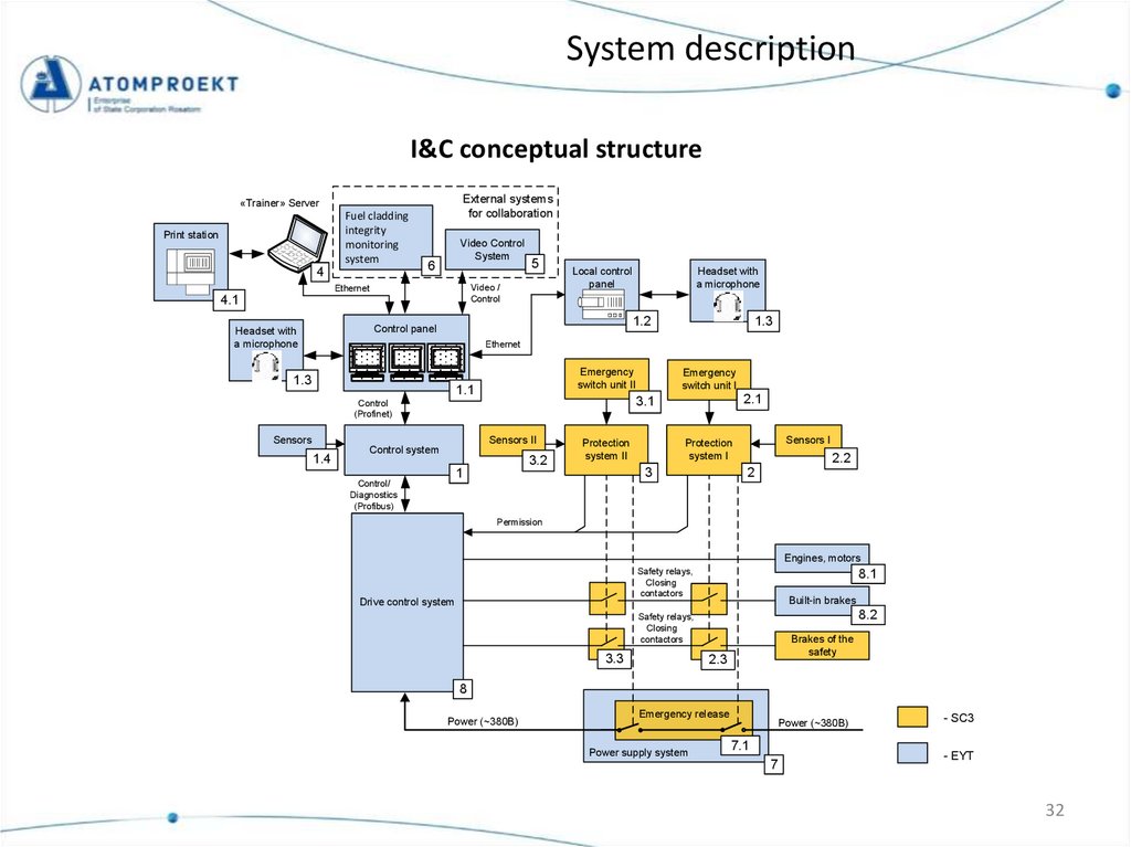
System descriptionI&C conceptual structure
External systems
for collaboration
«Trainer» Server
Fuel cladding
integrity
monitoring
system
Print station
4
Video Control
System
6
5
Video /
Control
Ethernet
4.1
Local control
panel
1.2
Control panel
Headset with
a microphone
Headset with
a microphone
1.3
Ethernet
1.3
Emergency
switch unit II
1.1
1.4
Sensors II
Control system
3.2
Protection
system II
Sensors I
Protection
system I
3
1
Control/
Diagnostics
(Profibus)
2.1
3.1
Control
(Profinet)
Sensors
Emergency
switch unit I
2.2
2
Permission
Engines, motors
Safety relays,
Closing
contactors
Drive control system
8.1
Built-in brakes
8.2
Safety relays,
Closing
contactors
3.3
Brakes of the
safety
2.3
8
Power (~380В)
Emergency release
Power supply system
Power (~380В)
7.1
7
- SC3
- EYT
32
33.
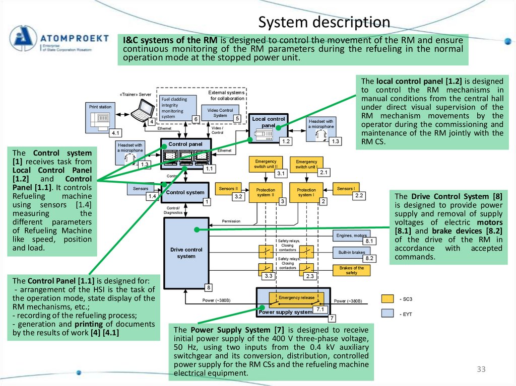
System descriptionI&C systems of the RM is designed to control the movement of the RM and ensure
continuous monitoring of the RM parameters during the refueling in the normal
operation mode at the stopped power unit.
External systems
for collaboration
«Trainer» Server
Fuel cladding
integrity
monitoring
system
Print station
4
Video Control
System
6
4.1
The Control system
[1] receives task from
Local Control Panel
[1.2] and Control
Panel [1.1]. It controls
Refueling
machine
using sensors [1.4]
measuring
the
different parameters
of Refueling Machine
like speed, position
and load.
5
Video /
Control
Ethernet
Local control
panel
Headset with
a microphone
1.2
Control panel
Headset with
a microphone
The local control panel [1.2] is designed
to control the RM mechanisms in
manual conditions from the central hall
under direct visual supervision of the
RM mechanism movements by the
operator during the commissioning and
maintenance of the RM jointly with the
RM CS.
1.3
Ethernet
1.3
Emergency
switch unit II
1.1
1.4
The Control Panel [1.1] is designed for:
- arrangement of the HSI is the task of
the operation mode, state display of the
RM mechanisms, etc.;
- recording of the refueling process;
- generation and printing of documents
by the results of work [4] [4.1]
Sensors II
Control system
2.1
3.1
Control
Sensors
Emergency
switch unit I
3.2
Protection
system II
3
1
Sensors I
Protection
system I
2.2
2
Control/
Diagnostics
Permission
Engines, motors
8.1
Safety relays,
Closing
contactors
Drive control
system
Built-in brakes
8.2
Safety relays,
Closing
contactors
3.3
The Drive Control System [8]
is designed to provide power
supply and removal of supply
voltages of electric motors
[8.1] and brake devices [8.2]
of the drive of the RM in
accordance with accepted
commands.
Brakes of the
safety
2.3
8
Power (~380В)
Emergency release
Power supply system
Power (~380В)
- SC3
7.1
7
The Power Supply System [7] is designed to receive
initial power supply of the 400 V three-phase voltage,
50 Hz, using two inputs from the 0.4 kV auxiliary
switchgear and its conversion, distribution, controlled
power supply for the RM CSs and the refueling machine
electrical equipment.
- EYT
33
34.
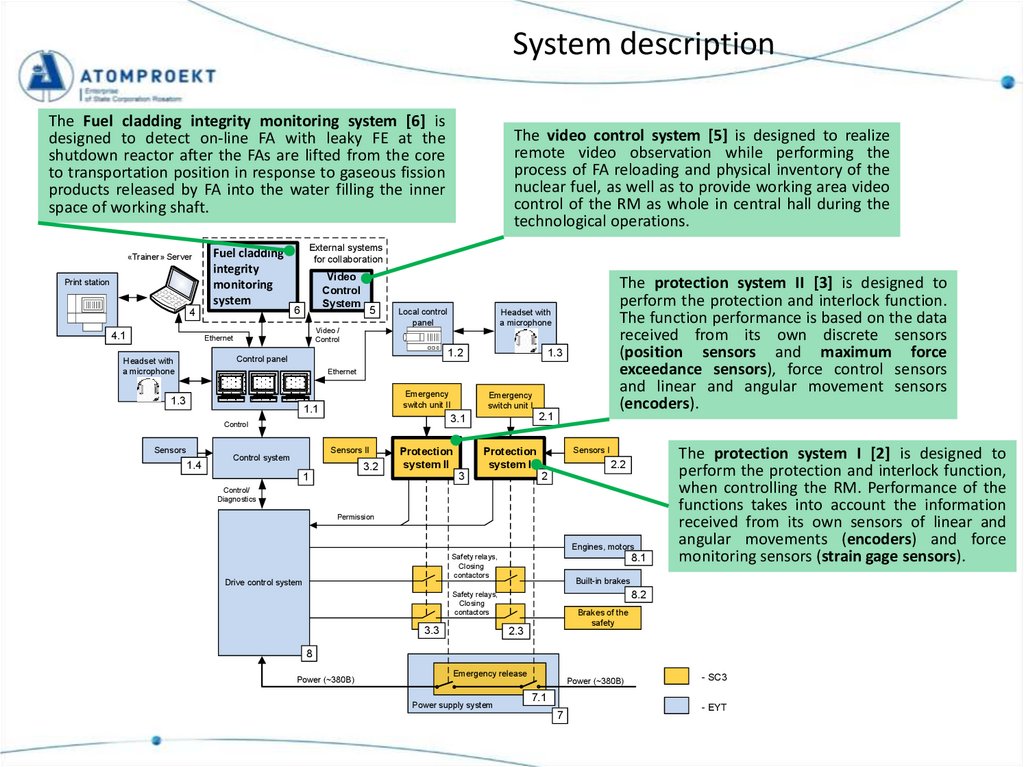
System descriptionThe Fuel cladding integrity monitoring system [6] is
designed to detect on-line FA with leaky FE at the
shutdown reactor after the FAs are lifted from the core
to transportation position in response to gaseous fission
products released by FA into the water filling the inner
space of working shaft.
«Trainer» Server
Print station
Fuel cladding
integrity
monitoring
system
4
4.1
External systems
for collaboration
Video
Control
System
6
5
Local control
panel
The protection system II [3] is designed to
perform the protection and interlock function.
The function performance is based on the data
received from its own discrete sensors
(position sensors and maximum force
exceedance sensors), force control sensors
and linear and angular movement sensors
(encoders).
Headset with
a microphone
Video /
Control
Ethernet
1.2
Control panel
Headset with
a microphone
The video control system [5] is designed to realize
remote video observation while performing the
process of FA reloading and physical inventory of the
nuclear fuel, as well as to provide working area video
control of the RM as whole in central hall during the
technological operations.
1.3
Ethernet
1.3
Emergency
switch unit II
1.1
1.4
Sensors II
Control system
2.1
3.1
Control
Sensors
Emergency
switch unit I
3.2
Protection
system II
3
1
Sensors I
Protection
system I
2.2
2
Control/
Diagnostics
Permission
Engines, motors
8.1
Safety relays,
Closing
contactors
Drive control system
Built-in brakes
8.2
Safety relays,
Closing
contactors
3.3
The protection system I [2] is designed to
perform the protection and interlock function,
when controlling the RM. Performance of the
functions takes into account the information
received from its own sensors of linear and
angular movements (encoders) and force
monitoring sensors (strain gage sensors).
Brakes of the
safety
2.3
8
Power (~380В)
Emergency release
Power supply system
Power (~380В)
- SC3
7.1
7
- EYT
35.
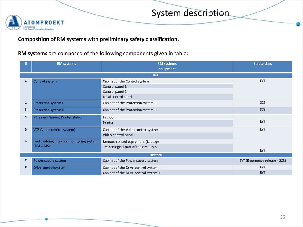
System descriptionComposition of RM systems with preliminary safety classification.
RM systems are composed of the following components given in table:
RM systems
#
RM systems
equipment
Safety class
I&C
1
Control system
Cabinet of the Control system
Control panel 1
Control panel 2
Local control panel
EYT
2
Protection system I
Cabinet of the Protection system I
SC3
3
Protection system II
Cabinet of the Protection system II
SC3
4
«Trainer» Server, Printer station
Laptop
Printer
EYT
5
VCS (Video control system)
Cabinet of the Video control system
Video control panel
6
Fuel cladding integrity monitoring system
(RM CIMS)
Remote control equipment (Laptop)
Technological part of the RM CIMS
EYT
EYT
Electrical
7
Power supply system
Cabinet of the Power supply system
EYT (Emergency release - SC3)
8
Drive control system
Cabinet of the Drive control system I
Cabinet of the Drive control system II
EYT
EYT
35
36.
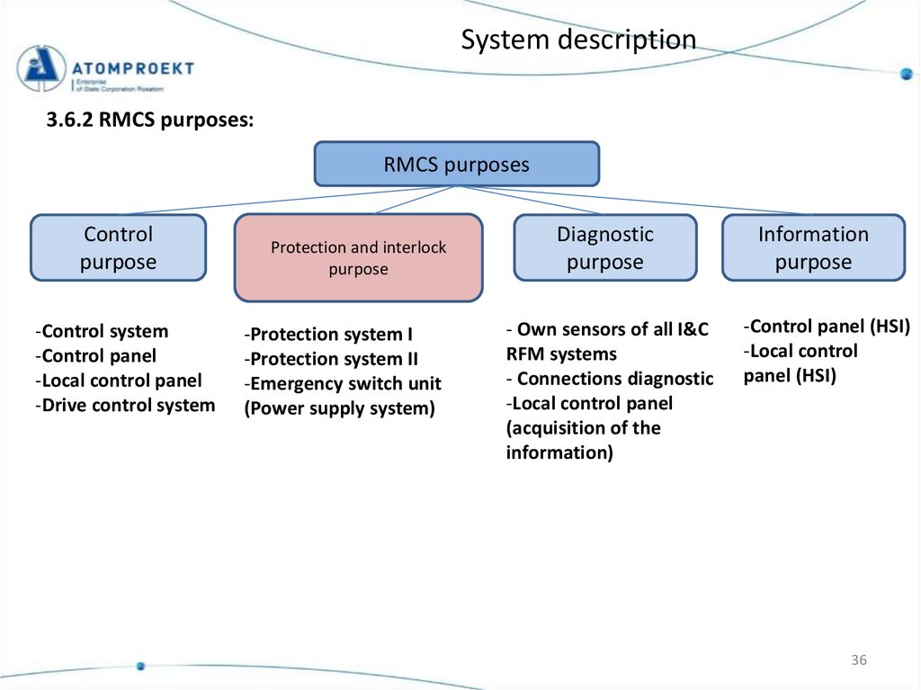
System description3.6.2 RMCS purposes:
RMCS purposes
Control
purpose
-Control system
-Control panel
-Local control panel
-Drive control system
Protection and interlock
purpose
-Protection system I
-Protection system II
-Emergency switch unit
(Power supply system)
Diagnostic
purpose
- Own sensors of all I&C
RFM systems
- Connections diagnostic
-Local control panel
(acquisition of the
information)
Information
purpose
-Control panel (HSI)
-Local control
panel (HSI)
36
37.
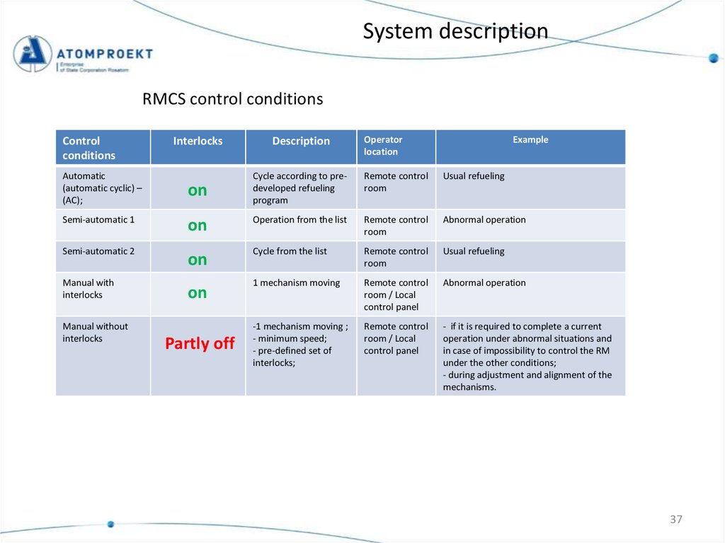
System descriptionRMCS control conditions
Control
conditions
Automatic
(automatic cyclic) –
(AC);
Operator
location
Example
Interlocks
Description
Remote control
room
Usual refueling
on
Cycle according to predeveloped refueling
program
Semi-automatic 1
on
Operation from the list
Remote control
room
Abnormal operation
Semi-automatic 2
on
Cycle from the list
Remote control
room
Usual refueling
1 mechanism moving
Remote control
room / Local
control panel
Abnormal operation
-1 mechanism moving ;
- minimum speed;
- pre-defined set of
interlocks;
Remote control
room / Local
control panel
- if it is required to complete a current
operation under abnormal situations and
in case of impossibility to control the RM
under the other conditions;
- during adjustment and alignment of the
mechanisms.
Manual with
interlocks
Manual without
interlocks
on
Partly off
37
38.
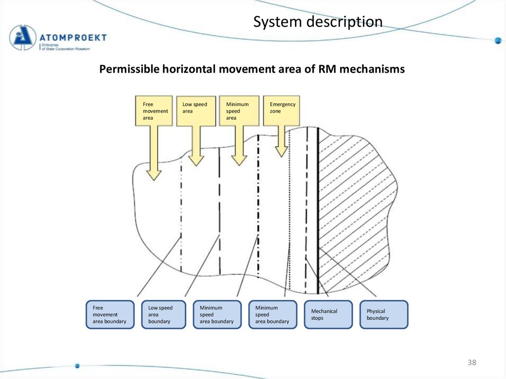
System descriptionPermissible horizontal movement area of RM mechanisms
Free
movement
area
Free
movement
area boundary
Low speed
area
boundary
Low speed
area
Minimum
speed
area
Minimum
speed
area boundary
Emergency
zone
Minimum
speed
area boundary
Mechanical
stops
Physical
boundary
38
39.
PRESENTATION CONTENTSSAFETY ENGINEERING PLAN FOR FUEL HANDLING (SEP-FH)
FUNCTIONAL SAFETY DESIGN & ARCHITECTURE (FSDA)
SYSTEM REQUIREMENT SPECIFICATION (SRS)
SYSTEM DESCRIPTION (SD)
SYSTEM REQUIREMENT EVALUATION (SRE)
39
40.
System Requirement EvaluationThis document includes the list of requirements developed in the System requirement
specification document for RM and references to the System description document where
performance of the given requirements is shown. Moreover, this document includes the
information on properties and the status of requirements and system description. The
document is developed in accordance with the KAA pilot.
Example:
40
41.
Thank youyour
attention!
Thank
youforfor
attention
41
42.
Thank youyour
attention!
Thank
youforfor
attention
42
43.
Thank youyour
attention!
Thank
youforfor
attention
43