
 internet
 programming
Similar presentations:


Control and monitoring system (CMS)
1.
TRAINING COURSECONTROL AND MONITORING SYSTEM
(CMS)
Primary Surveillance Radar Systems
Doc. Nº: 0066511000011MA00
Edition: 4 Revision: 0
Date: 28/05/2015
2.
WARNING OF CONFIDENTIALITYWarning of Confidentiality
Indra owns the copyright of this document which is supplied confidentially and must not be used for
any purpose other than that for which it is supplied. It must not be reproduced either wholly or
partially, copied or transmitted to any person without the authorization of Indra.
Control and Monitoring System (CMS)
0066511000011MA00 _4_0
28/05/2015
| 2
3.
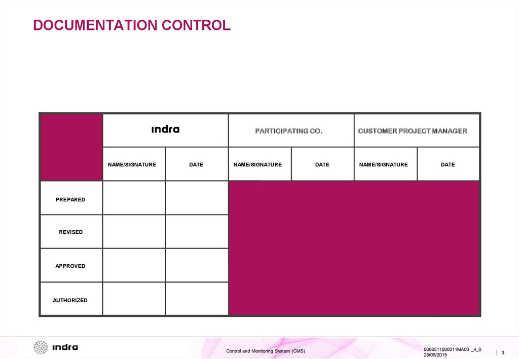
DOCUMENTATION CONTROLPARTICIPATING CO.
NAME/SIGNATURE
DATE
NAME/SIGNATURE
DATE
CUSTOMER PROJECT MANAGER
NAME/SIGNATURE
DATE
PREPARED
REVISED
APPROVED
AUTHORIZED
Control and Monitoring System (CMS)
0066511000011MA00 _4_0
28/05/2015
| 3
4.
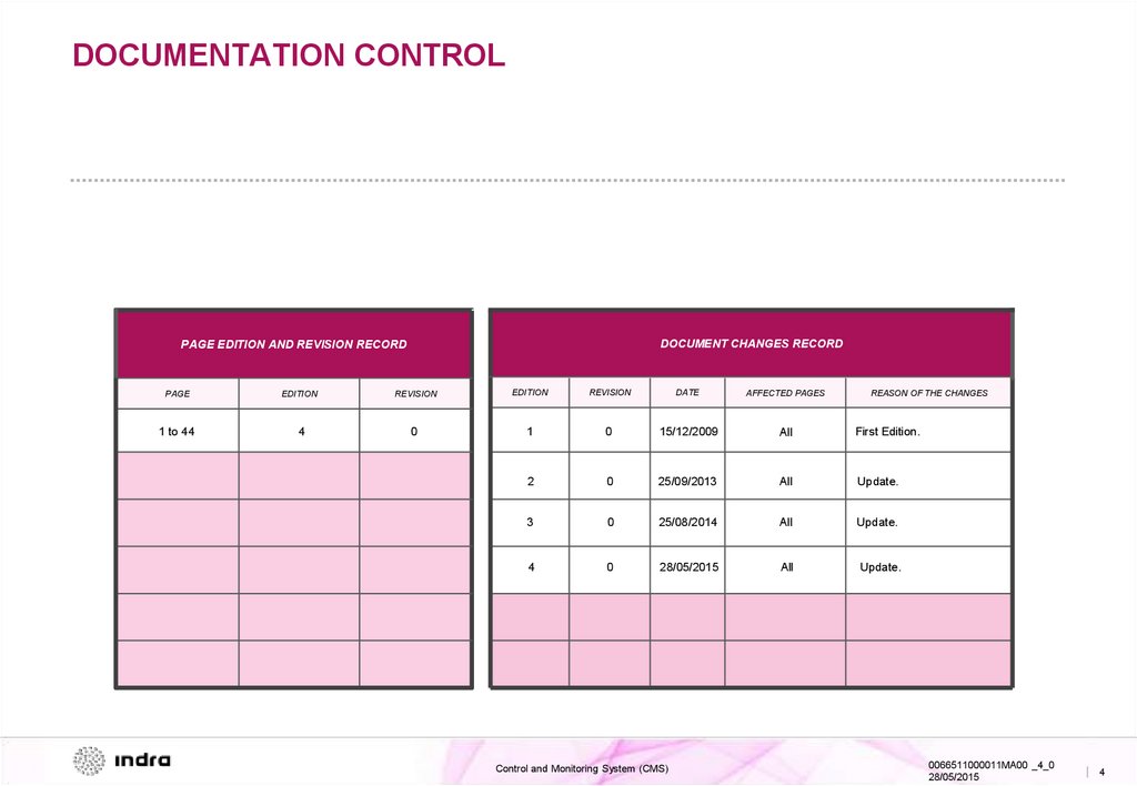
DOCUMENTATION CONTROLDOCUMENT CHANGES RECORD
PAGE EDITION AND REVISION RECORD
PAGE
EDITION
REVISION
EDITION
REVISION
DATE
AFFECTED PAGES
1 to 44
4
0
1
0
15/12/2009
All
First Edition.
2
0
25/09/2013
All
Update.
3
0
25/08/2014
All
Update.
4
0
28/05/2015
All
Update.
Control and Monitoring System (CMS)
REASON OF THE CHANGES
0066511000011MA00 _4_0
28/05/2015
| 4
5.
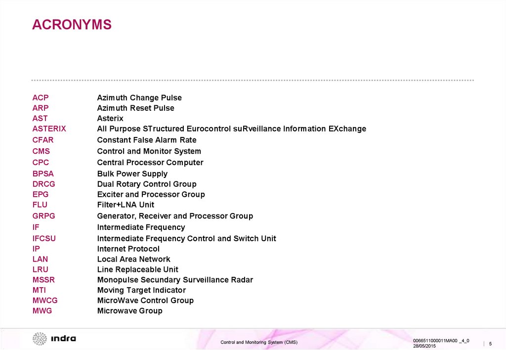
ACRONYMSACP
ARP
AST
ASTERIX
CFAR
CMS
CPC
BPSA
DRCG
EPG
FLU
GRPG
IF
IFCSU
IP
LAN
LRU
MSSR
MTI
MWCG
MWG
Azimuth Change Pulse
Azimuth Reset Pulse
Asterix
All Purpose STructured Eurocontrol suRveillance Information EXchange
Constant False Alarm Rate
Control and Monitor System
Central Processor Computer
Bulk Power Supply
Dual Rotary Control Group
Exciter and Processor Group
Filter+LNA Unit
Generator, Receiver and Processor Group
Intermediate Frequency
Intermediate Frequency Control and Switch Unit
Internet Protocol
Local Area Network
Line Replaceable Unit
Monopulse Secundary Surveillance Radar
Moving Target Indicator
MicroWave Control Group
Microwave Group
Control and Monitoring System (CMS)
0066511000011MA00 _4_0
28/05/2015
| 5
6.
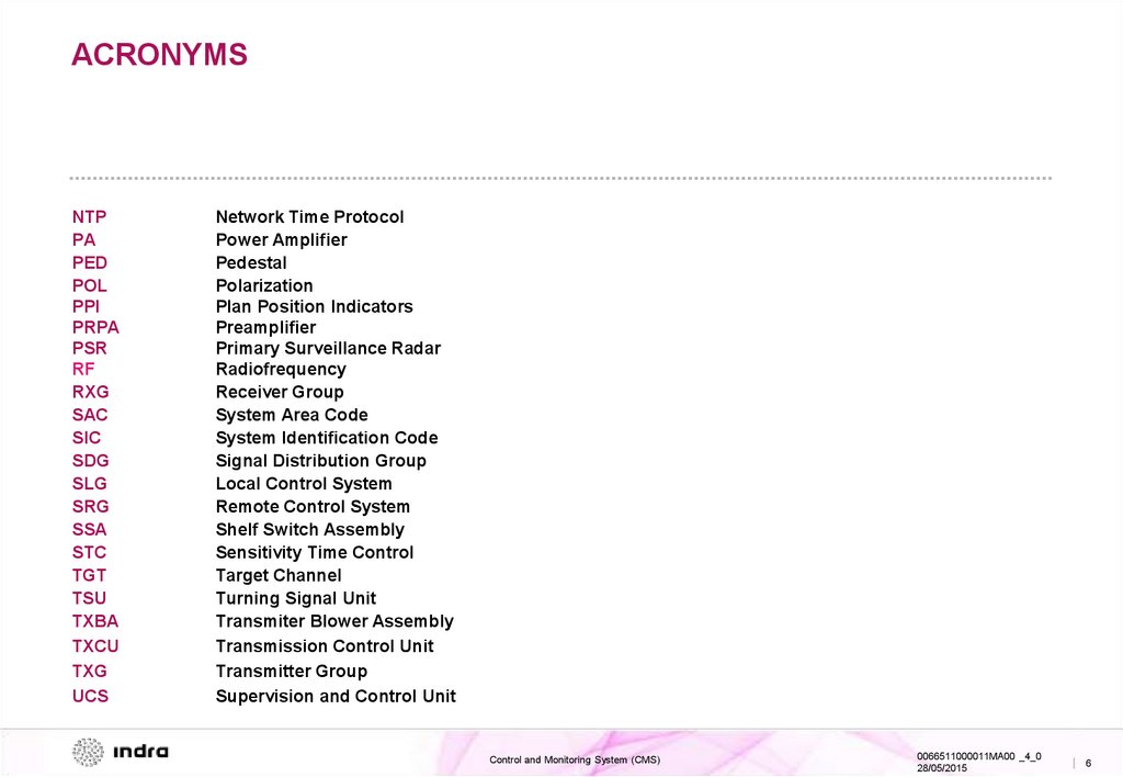
ACRONYMSNTP
PA
PED
POL
PPI
PRPA
PSR
RF
RXG
SAC
SIC
SDG
SLG
SRG
SSA
STC
TGT
TSU
TXBA
TXCU
TXG
UCS
Network Time Protocol
Power Amplifier
Pedestal
Polarization
Plan Position Indicators
Preamplifier
Primary Surveillance Radar
Radiofrequency
Receiver Group
System Area Code
System Identification Code
Signal Distribution Group
Local Control System
Remote Control System
Shelf Switch Assembly
Sensitivity Time Control
Target Channel
Turning Signal Unit
Transmiter Blower Assembly
Transmission Control Unit
Transmitter Group
Supervision and Control Unit
Control and Monitoring System (CMS)
0066511000011MA00 _4_0
28/05/2015
| 6
7.
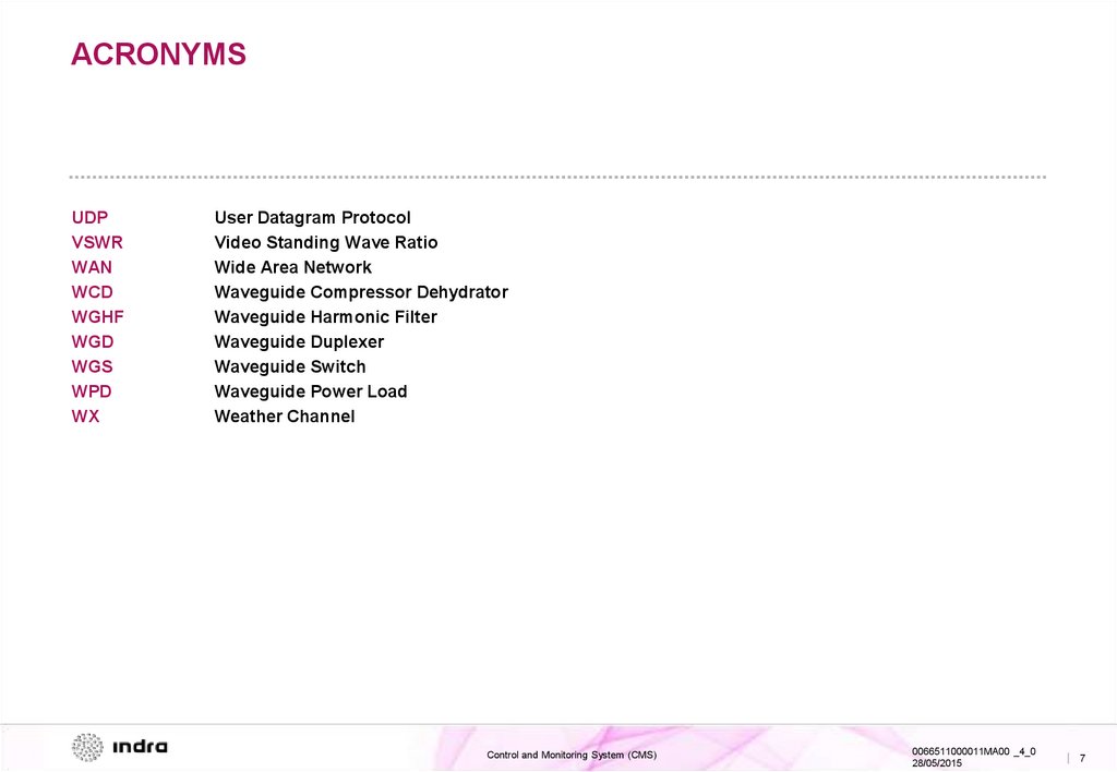
ACRONYMSUDP
VSWR
WAN
WCD
WGHF
WGD
WGS
WPD
WX
User Datagram Protocol
Video Standing Wave Ratio
Wide Area Network
Waveguide Compressor Dehydrator
Waveguide Harmonic Filter
Waveguide Duplexer
Waveguide Switch
Waveguide Power Load
Weather Channel
Control and Monitoring System (CMS)
0066511000011MA00 _4_0
28/05/2015
| 7
8.
INDEX01 General Description
System Overview
Block Diagram
Functional Description
02 Description of Elements
PSR CMS Main Screen
Pedestal CMS Main Screen
03 Operation and Monitoring
SRG Main screen
SLG Main screen
Colour code
PSR CMS Main screen
PSR CMS Monitoring
PSR CMS Operation
Pedestal CMS Main screen
Pedestal CMS Monitoring
Pedestal CMS Operation
Control and Monitoring System (CMS)
0066511000011MA00 _4_0
28/05/2015
| 8
9.
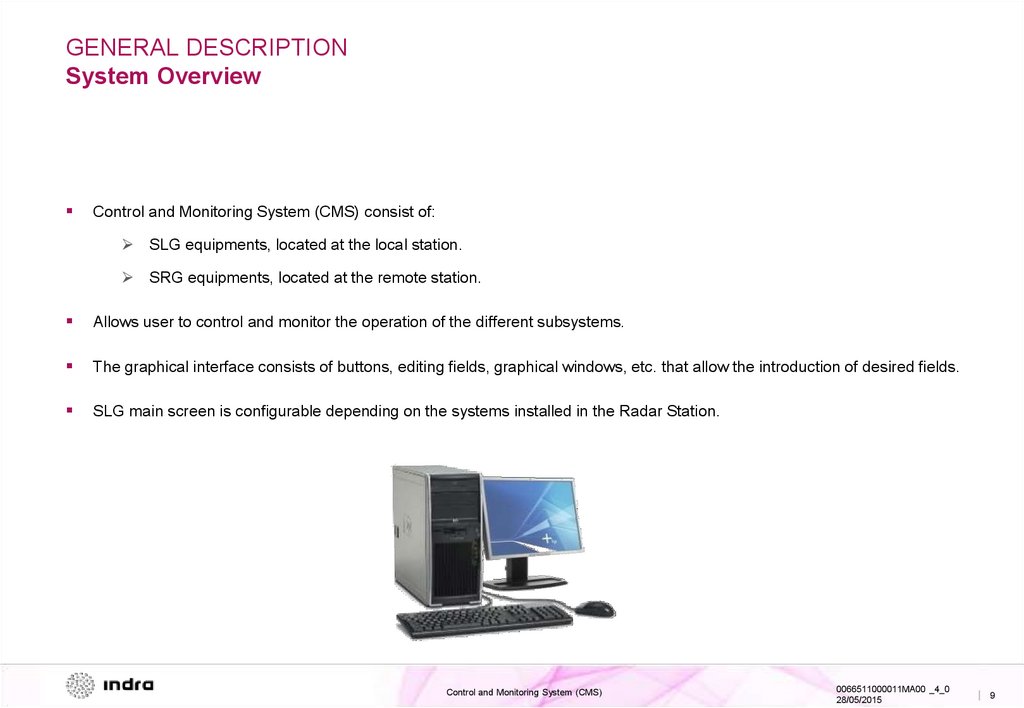
GENERAL DESCRIPTIONSystem Overview
Control and Monitoring System (CMS) consist of:
SLG equipments, located at the local station.
SRG equipments, located at the remote station.
Allows user to control and monitor the operation of the different subsystems.
The graphical interface consists of buttons, editing fields, graphical windows, etc. that allow the introduction of desired fields.
SLG main screen is configurable depending on the systems installed in the Radar Station.
Control and Monitoring System (CMS)
0066511000011MA00 _4_0
28/05/2015
| 9
10.
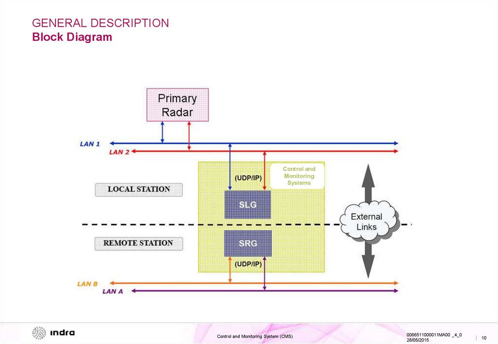
GENERAL DESCRIPTIONBlock Diagram
Control and
Monitoring
Systems
Control and Monitoring System (CMS)
0066511000011MA00 _4_0
28/05/2015
| 10
11.
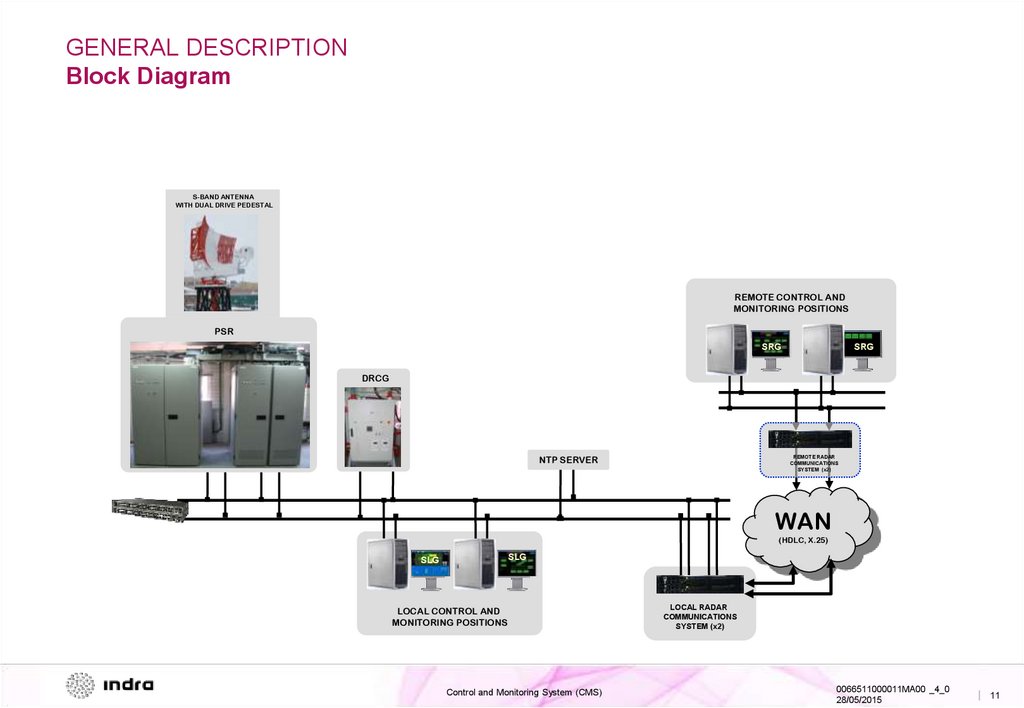
GENERAL DESCRIPTIONBlock Diagram
S-BAND ANTENNA
WITH DUAL DRIVE PEDESTAL
REMOTE CONTROL AND
MONITORING POSITIONS
PSR
SRG
SRG
DRCG
NTP SERVER
REMOTE RADAR
COMMUNICATIONS
SYSTEM (x2)
WAN
(HDLC, X.25)
SLG
SLG
LOCAL CONTROL AND
MONITORING POSITIONS
Control and Monitoring System (CMS)
LOCAL RADAR
COMMUNICATIONS
SYSTEM (x2)
0066511000011MA00 _4_0
28/05/2015
| 11
12.
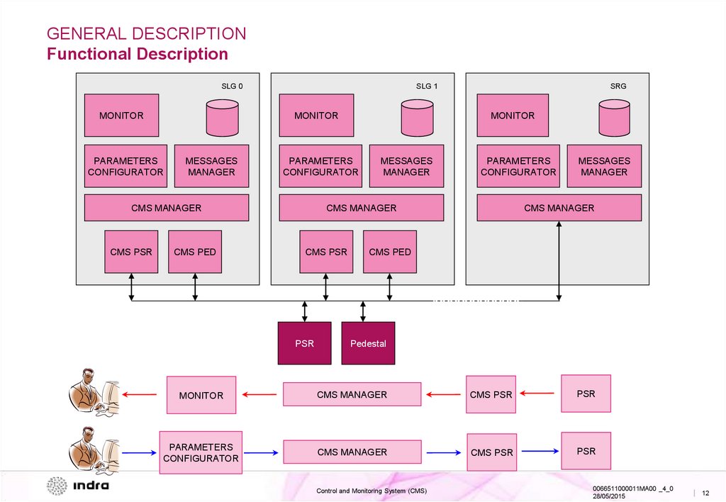
GENERAL DESCRIPTIONFunctional Description
SLG 0
MONITOR
SLG 1
MONITOR
PARAMETERS
CONFIGURATOR
MESSAGES
MANAGER
CMS PSR
CMS PED
MONITOR
PARAMETERS
CONFIGURATOR
CMS MANAGER
SRG
MESSAGES
MANAGER
PARAMETERS
CONFIGURATOR
CMS MANAGER
CMS PSR
PSR
MESSAGES
MANAGER
CMS MANAGER
CMS PED
Pedestal
MONITOR
CMS MANAGER
CMS PSR
PSR
PARAMETERS
CONFIGURATOR
CMS MANAGER
CMS PSR
PSR
Control and Monitoring System (CMS)
0066511000011MA00 _4_0
28/05/2015
| 12
13.
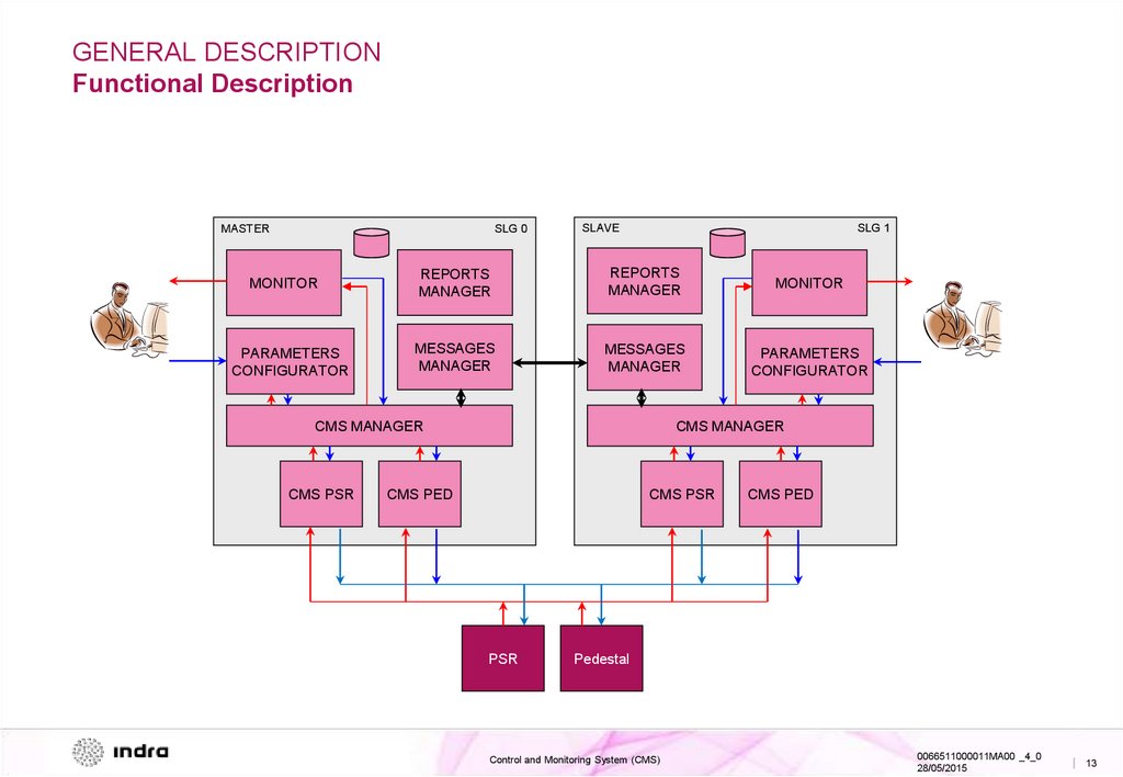
GENERAL DESCRIPTIONFunctional Description
MASTER
SLG 0
MONITOR
PARAMETERS
CONFIGURATOR
SLAVE
SLG 1
REPORTS
MANAGER
REPORTS
MANAGER
MONITOR
MESSAGES
MANAGER
MESSAGES
MANAGER
PARAMETERS
CONFIGURATOR
CMS MANAGER
CMS PSR
CMS MANAGER
CMS PED
CMS PSR
PSR
CMS PED
Pedestal
Control and Monitoring System (CMS)
0066511000011MA00 _4_0
28/05/2015
| 13
14.
GENERAL DESCRIPTIONFunctional Description
The main functions of Local Management System are:
CONTROL: Allows user to change parameters and to configure management systems.
MONITORING: Displays the status of different subsystems in real time.
In order to perform these functions, the main software applications are:
CMS PSR: Control and Monitoring Unit, allows modification of processing parameters and control of all the PSR
system functions. It also displays the status of the system at LRU level.
CMS Pedestal: Common to SSR co-mounted system (if exists). It controls and monitors the Antenna and Pedestal
Group.
Control and Monitoring System (CMS)
0066511000011MA00 _4_0
28/05/2015
| 14
15.
INDEX01 General Description
System Overview
Block Diagram
Functional Description
02 Description of Elements
PSR CMS Main Screen
Pedestal CMS Main Screen
03 Operation and Monitoring
SRG Main screen
SLG Main screen
Colour code
PSR CMS Main screen
PSR CMS Monitoring
PSR CMS Operation
Pedestal CMS Main screen
Pedestal CMS Monitoring
Pedestal CMS Operation
Control and Monitoring System (CMS)
0066511000011MA00 _4_0
28/05/2015
| 15
16.
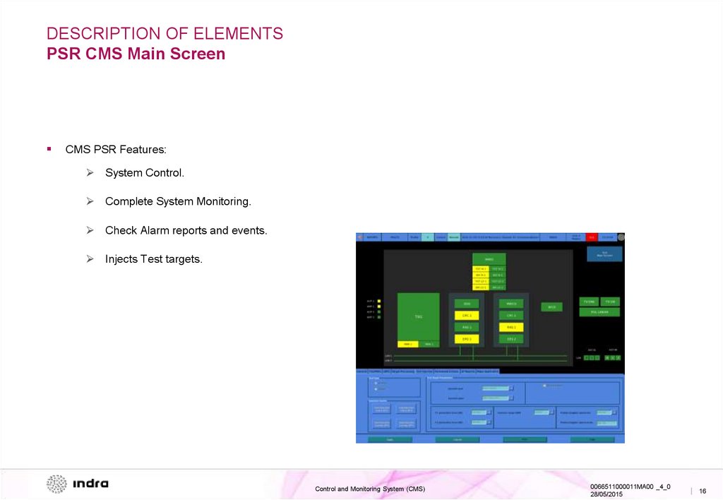
DESCRIPTION OF ELEMENTSPSR CMS Main Screen
CMS PSR Features:
System Control.
Complete System Monitoring.
Check Alarm reports and events.
Injects Test targets.
Control and Monitoring System (CMS)
0066511000011MA00 _4_0
28/05/2015
| 16
17.
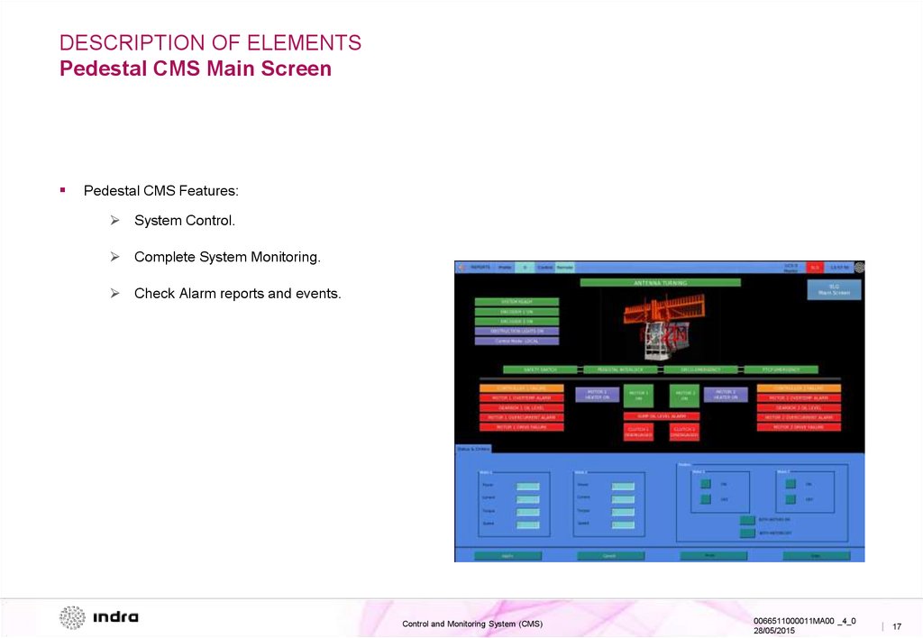
DESCRIPTION OF ELEMENTSPedestal CMS Main Screen
Pedestal CMS Features:
System Control.
Complete System Monitoring.
Check Alarm reports and events.
Control and Monitoring System (CMS)
0066511000011MA00 _4_0
28/05/2015
| 17
18.
INDEX01 General Description
System Overview
Block Diagram
Functional Description
02 Description of Elements
PSR CMS Main Screen
Pedestal CMS Main Screen
03 Operation and Monitoring
SRG Main screen
SLG Main screen
Colour code
PSR CMS Main screen
PSR CMS Monitoring
PSR CMS Operation
Pedestal CMS Main screen
Pedestal CMS Monitoring
Pedestal CMS Operation
Control and Monitoring System (CMS)
0066511000011MA00 _4_0
28/05/2015
| 18
19.
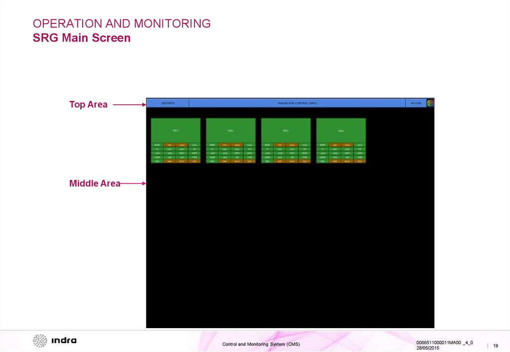
OPERATION AND MONITORINGSRG Main Screen
Top Area
Middle Area
Control and Monitoring System (CMS)
0066511000011MA00 _4_0
28/05/2015
| 19
20.
OPERATION AND MONITORINGSRG Main Screen
The main screen of the SRG shows two different areas:
Buttons area on top:
Button to access to alarm reports and events.
Site Name.
UTC time.
Indra logo: An information window with all the installed versions.
Middle Area, Graphical Diagrams:
Allows access to every Radar Site (up to 20 Radar Sites).
Control and Monitoring System (CMS)
0066511000011MA00 _4_0
28/05/2015
| 20
21.
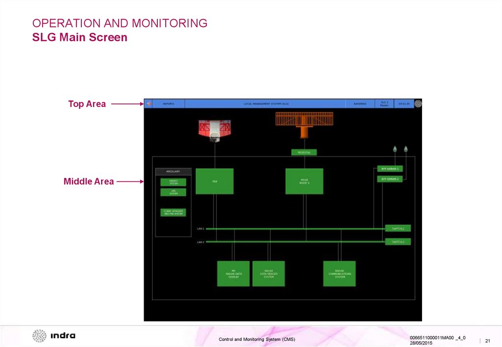
OPERATION AND MONITORINGSLG Main Screen
Top Area
Middle Area
Control and Monitoring System (CMS)
0066511000011MA00 _4_0
28/05/2015
| 21
22.
OPERATION AND MONITORINGSLG Main Screen
The main screen of the SLG level shows two different areas:
Buttons area on top:
Button to access to alarm reports and events.
Site Name.
Flags SLG X YY.
X: SLG ID Number (0, 1, 2…)
YY: Master / Slave
UTC time.
Indra logo: An information window with all the installed versions.
Middle Area, Graphical Diagrams:
Allows access to every subsystem, for instance the Primary Surveillance Radar.
Control and Monitoring System (CMS)
0066511000011MA00 _4_0
28/05/2015
| 22
23.
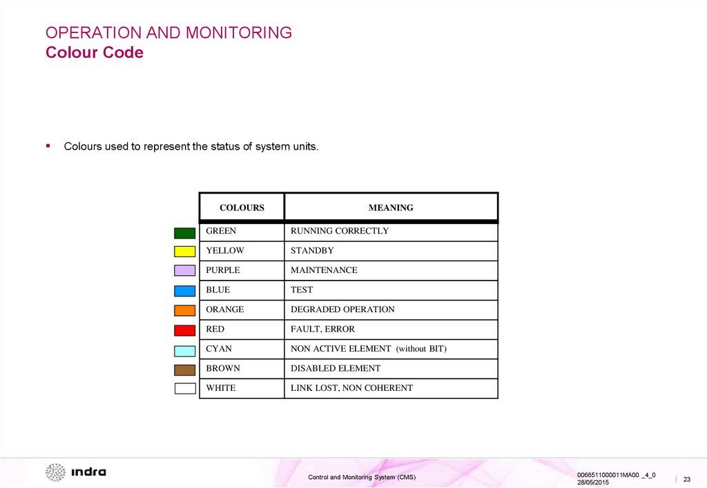
OPERATION AND MONITORINGColour Code
Colours used to represent the status of system units.
COLOURS
MEANING
GREEN
RUNNING CORRECTLY
YELLOW
STANDBY
PURPLE
MAINTENANCE
BLUE
TEST
ORANGE
DEGRADED OPERATION
RED
FAULT, ERROR
CYAN
NON ACTIVE ELEMENT (without BIT)
BROWN
DISABLED ELEMENT
WHITE
LINK LOST, NON COHERENT
Control and Monitoring System (CMS)
0066511000011MA00 _4_0
28/05/2015
| 23
24.
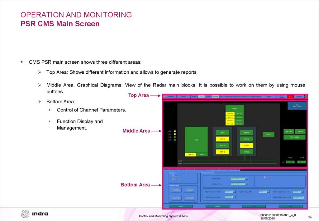
OPERATION AND MONITORINGPSR CMS Main Screen
CMS PSR main screen shows three different areas:
Top Area: Shows different information and allows to generate reports.
Middle Area, Graphical Diagrams: View of the Radar main blocks. It is possible to work on them by using mouse
buttons.
Top Area
Bottom Area:
Control of Channel Parameters.
Function Display and
Management.
Middle Area
Bottom Area
Control and Monitoring System (CMS)
0066511000011MA00 _4_0
28/05/2015
| 24
25.
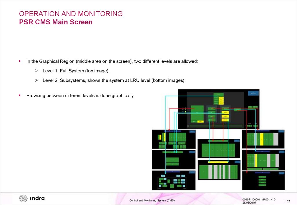
OPERATION AND MONITORINGPSR CMS Main Screen
In the Graphical Region (middle area on the screen), two different levels are allowed:
Level 1: Full System (top image).
Level 2: Subsystems, shows the system at LRU level (bottom images).
Browsing between different levels is done graphically.
Control and Monitoring System (CMS)
0066511000011MA00 _4_0
28/05/2015
| 25
26.
OPERATION AND MONITORINGPSR CMS Monitoring
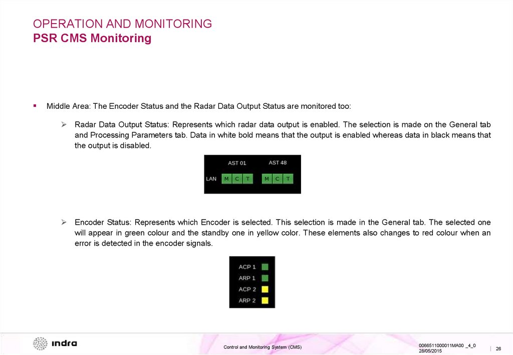
Middle Area: The Encoder Status and the Radar Data Output Status are monitored too:
Radar Data Output Status: Represents which radar data output is enabled. The selection is made on the General tab
and Processing Parameters tab. Data in white bold means that the output is enabled whereas data in black means that
the output is disabled.
Encoder Status: Represents which Encoder is selected. This selection is made in the General tab. The selected one
will appear in green colour and the standby one in yellow color. These elements also changes to red colour when an
error is detected in the encoder signals.
Control and Monitoring System (CMS)
0066511000011MA00 _4_0
28/05/2015
| 26
27.
OPERATION AND MONITORINGPSR CMS Monitoring
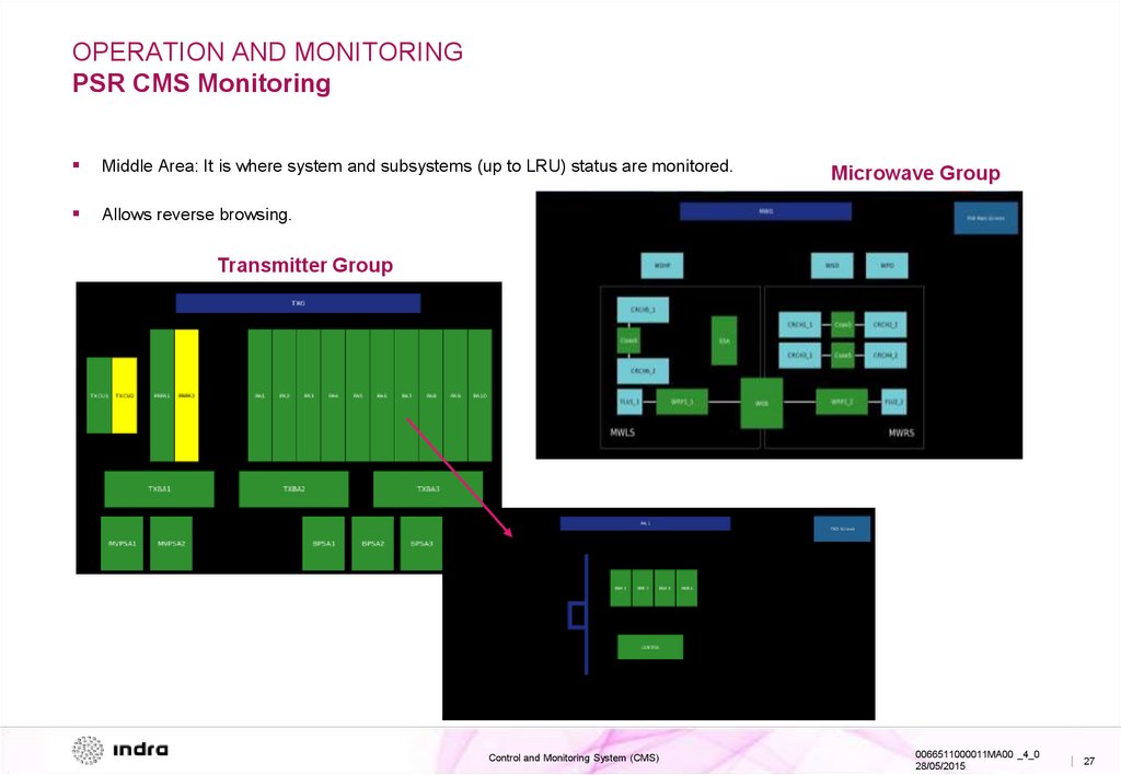
Middle Area: It is where system and subsystems (up to LRU) status are monitored.
Allows reverse browsing.
Microwave Group
Transmitter Group
Control and Monitoring System (CMS)
0066511000011MA00 _4_0
28/05/2015
| 27
28.
OPERATION AND MONITORINGPSR CMS Monitoring
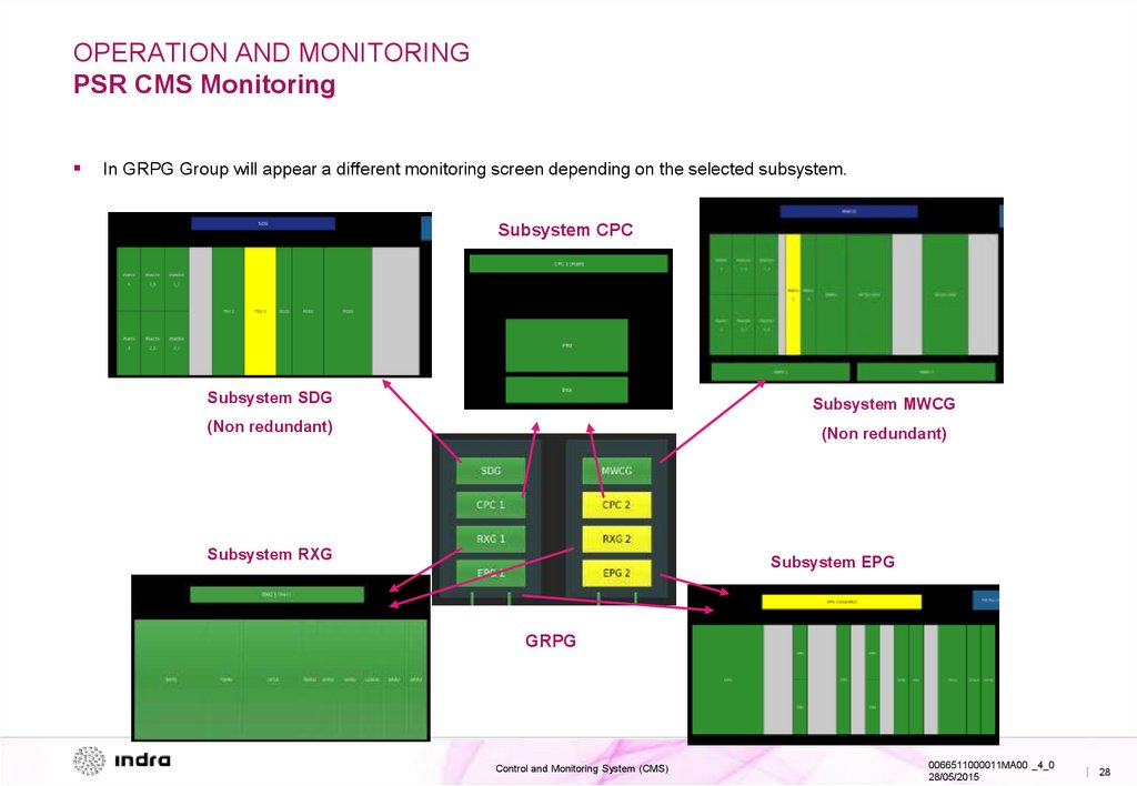
In GRPG Group will appear a different monitoring screen depending on the selected subsystem.
Subsystem CPC
Subsystem SDG
Subsystem MWCG
(Non redundant)
(Non redundant)
Subsystem RXG
Subsystem EPG
GRPG
Control and Monitoring System (CMS)
0066511000011MA00 _4_0
28/05/2015
| 28
29.
OPERATION AND MONITORINGPSR CMS Monitoring
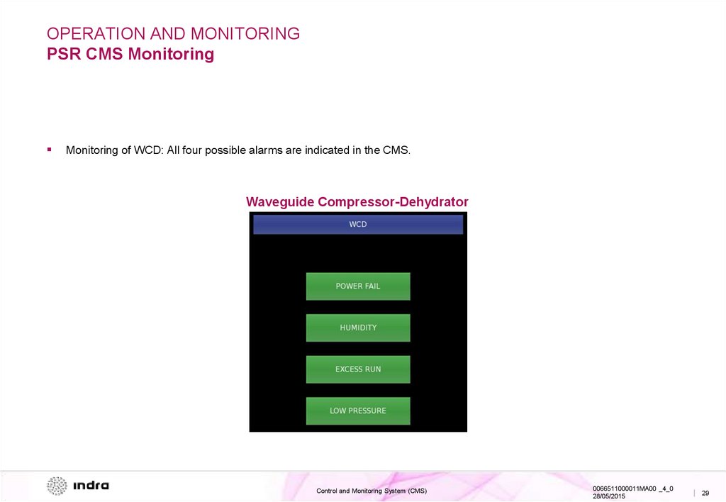
Monitoring of WCD: All four possible alarms are indicated in the CMS.
Waveguide Compressor-Dehydrator
Control and Monitoring System (CMS)
0066511000011MA00 _4_0
28/05/2015
| 29
30.
OPERATION AND MONITORINGPSR CMS Operation
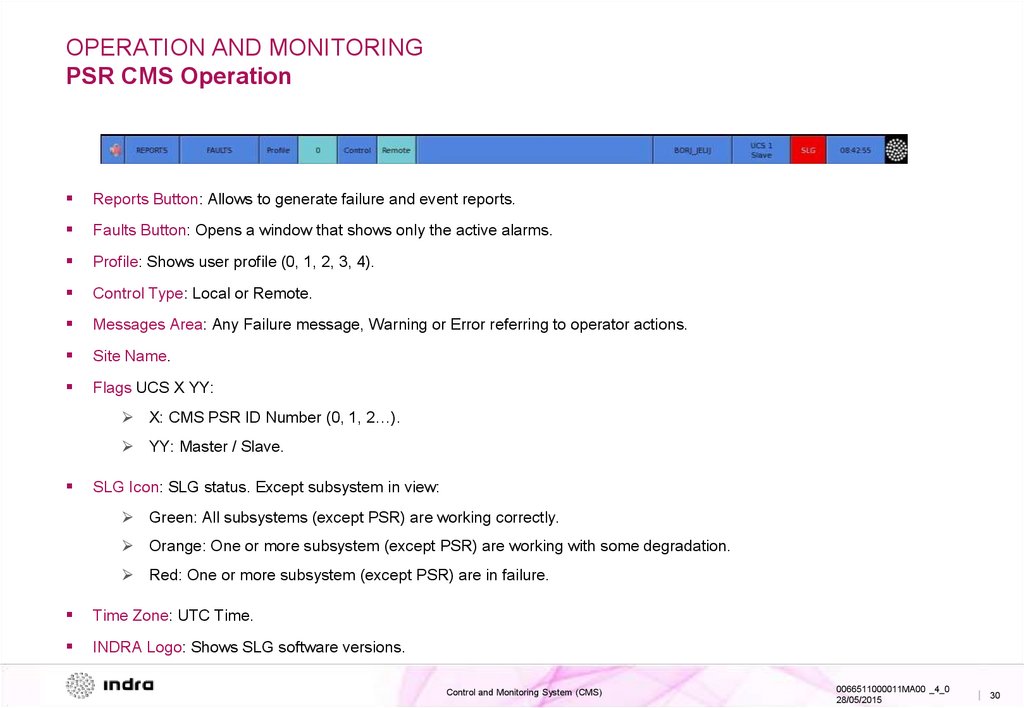
Reports Button: Allows to generate failure and event reports.
Faults Button: Opens a window that shows only the active alarms.
Profile: Shows user profile (0, 1, 2, 3, 4).
Control Type: Local or Remote.
Messages Area: Any Failure message, Warning or Error referring to operator actions.
Site Name.
Flags UCS X YY:
X: CMS PSR ID Number (0, 1, 2…).
YY: Master / Slave.
SLG Icon: SLG status. Except subsystem in view:
Green: All subsystems (except PSR) are working correctly.
Orange: One or more subsystem (except PSR) are working with some degradation.
Red: One or more subsystem (except PSR) are in failure.
Time Zone: UTC Time.
INDRA Logo: Shows SLG software versions.
Control and Monitoring System (CMS)
0066511000011MA00 _4_0
28/05/2015
| 30
31.
OPERATION AND MONITORINGPSR CMS Operation
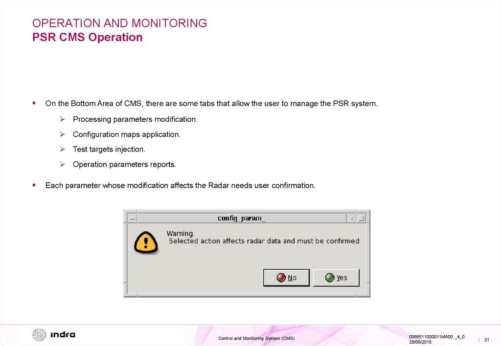
On the Bottom Area of CMS, there are some tabs that allow the user to manage the PSR system.
Processing parameters modification.
Configuration maps application.
Test targets injection.
Operation parameters reports.
Each parameter whose modification affects the Radar needs user confirmation.
Control and Monitoring System (CMS)
0066511000011MA00 _4_0
28/05/2015
| 31
32.
OPERATION AND MONITORINGPSR CMS Operation
Available tabs:
General: General system controls.
TXG: Transmitter Group controls.
Processing Parameters: Editable parameters list for the processing algorithms.
Test Injection: Allows digital/analogic test targets injection.
Permanent Echoes: Up to 10 permanent echoes .
SP Reports: Shows the value of different parameters to check specifications.
DP Reports: Shows the value of different parameters for the defined Permanent Echoes.
Maps Application: To change applied configuration maps.
To apply parameters changes, press Apply Button is required to send the control message in almost all cases.
Control and Monitoring System (CMS)
0066511000011MA00 _4_0
28/05/2015
| 32
33.
OPERATION AND MONITORINGPSR CMS Operation
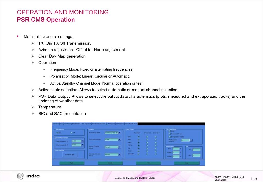
Main Tab: General settings.
TX On/ TX Off Transmission.
Azimuth adjustment: Offset for North adjustment.
Clear Day Map generation.
Operation:
Frequency Mode: Fixed or alternating frequencies.
Polarization Mode: Linear, Circular or Automatic.
Active/Standby Channel Mode: Normal operation or test.
Active chain selection: Allows to select automatic or manual channel selection.
PSR Data Output: Allows to select the output data characteristics (plots, measured and extrapolated tracks) and the
updating of weather data.
Temperature.
SIC and SAC presentation.
Control and Monitoring System (CMS)
0066511000011MA00 _4_0
28/05/2015
| 33
34.
OPERATION AND MONITORINGPSR CMS Operation
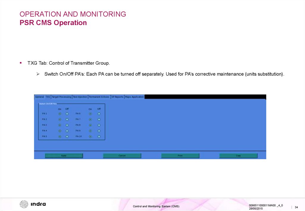
TXG Tab: Control of Transmitter Group.
Switch On/Off PA’s: Each PA can be turned off separately. Used for PA’s corrective maintenance (units substitution).
Control and Monitoring System (CMS)
0066511000011MA00 _4_0
28/05/2015
| 34
35.
OPERATION AND MONITORINGPSR CMS Operation
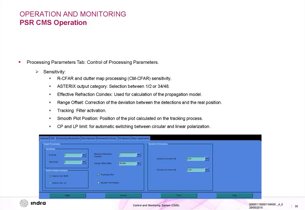
Processing Parameters Tab: Control of Processing Parameters.
Sensitivity:
R-CFAR and clutter map processing (CM-CFAR) sensitivity.
ASTERIX output category: Selection between 1/2 or 34/48.
Effective Refraction Coindex: Used for calculation of the propagation model.
Range Offset: Correction of the deviation between the detections and the real position.
Tracking Filter activation.
Smooth Plot Position: Position of the plot calculated on the tracking process.
CP and LP limit: for automatic switching between circular and linear polarization.
Control and Monitoring System (CMS)
0066511000011MA00 _4_0
28/05/2015
| 35
36.
OPERATION AND MONITORINGPSR CMS Operation
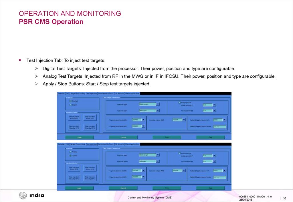
Test Injection Tab: To inject test targets.
Digital Test Targets: Injected from the processor. Their power, position and type are configurable.
Analog Test Targets: Injected from RF in the MWG or in IF in IFCSU. Their power, position and type are configurable.
Apply / Stop Buttons: Start / Stop test targets injected.
Control and Monitoring System (CMS)
0066511000011MA00 _4_0
28/05/2015
| 36
37.
OPERATION AND MONITORINGPSR CMS Operation
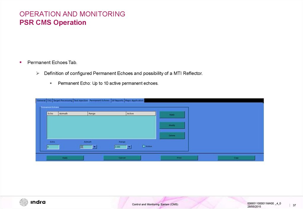
Permanent Echoes Tab.
Definition of configured Permanent Echoes and possibility of a MTI Reflector.
Permanent Echo: Up to 10 active permanent echoes.
Control and Monitoring System (CMS)
0066511000011MA00 _4_0
28/05/2015
| 37
38.
OPERATION AND MONITORINGPSR CMS Operation
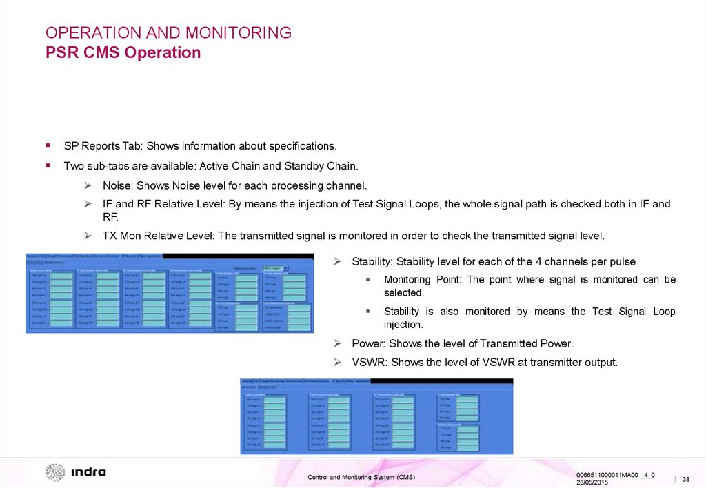
SP Reports Tab: Shows information about specifications.
Two sub-tabs are available: Active Chain and Standby Chain.
Noise: Shows Noise level for each processing channel.
IF and RF Relative Level: By means the injection of Test Signal Loops, the whole signal path is checked both in IF and
RF.
TX Mon Relative Level: The transmitted signal is monitored in order to check the transmitted signal level.
Stability: Stability level for each of the 4 channels per pulse
Monitoring Point: The point where signal is monitored can be
selected.
Stability is also monitored by means the Test Signal Loop
injection.
Power: Shows the level of Transmitted Power.
VSWR: Shows the level of VSWR at transmitter output.
Control and Monitoring System (CMS)
0066511000011MA00 _4_0
28/05/2015
| 38
39.
OPERATION AND MONITORINGPSR CMS Operation
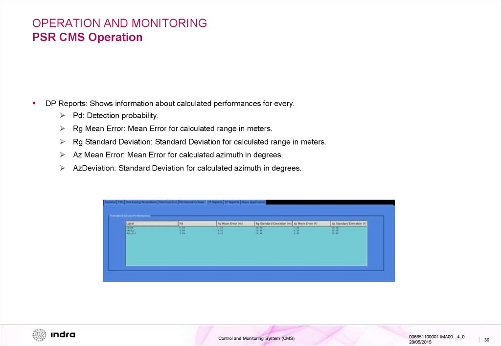
DP Reports: Shows information about calculated performances for every.
Pd: Detection probability.
Rg Mean Error: Mean Error for calculated range in meters.
Rg Standard Deviation: Standard Deviation for calculated range in meters.
Az Mean Error: Mean Error for calculated azimuth in degrees.
AzDeviation: Standard Deviation for calculated azimuth in degrees.
Control and Monitoring System (CMS)
0066511000011MA00 _4_0
28/05/2015
| 39
40.
OPERATION AND MONITORINGPSR CMS Operation
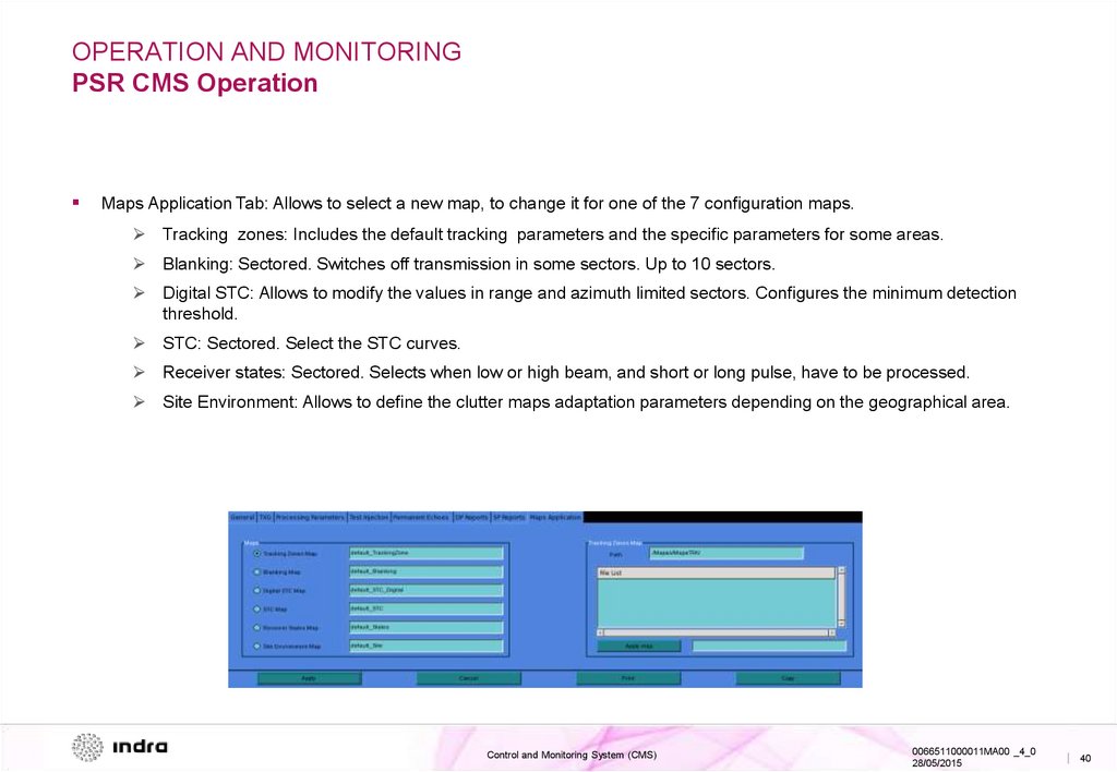
Maps Application Tab: Allows to select a new map, to change it for one of the 7 configuration maps.
Tracking zones: Includes the default tracking parameters and the specific parameters for some areas.
Blanking: Sectored. Switches off transmission in some sectors. Up to 10 sectors.
Digital STC: Allows to modify the values in range and azimuth limited sectors. Configures the minimum detection
threshold.
STC: Sectored. Select the STC curves.
Receiver states: Sectored. Selects when low or high beam, and short or long pulse, have to be processed.
Site Environment: Allows to define the clutter maps adaptation parameters depending on the geographical area.
Control and Monitoring System (CMS)
0066511000011MA00 _4_0
28/05/2015
| 40
41.
OPERATION AND MONITORINGPedestal CMS Main Screen
Top Area
Middle Area
Bottom Area
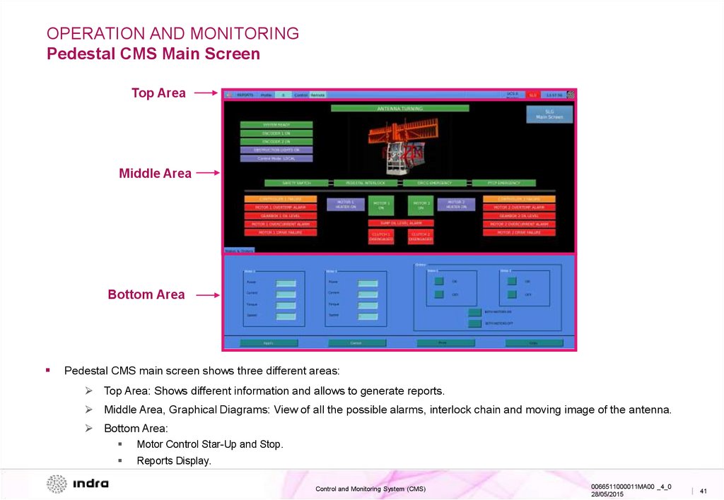
Pedestal CMS main screen shows three different areas:
Top Area: Shows different information and allows to generate reports.
Middle Area, Graphical Diagrams: View of all the possible alarms, interlock chain and moving image of the antenna.
Bottom Area:
Motor Control Star-Up and Stop.
Reports Display.
Control and Monitoring System (CMS)
0066511000011MA00 _4_0
28/05/2015
| 41
42.
OPERATION AND MONITORINGPedestal CMS Monitoring
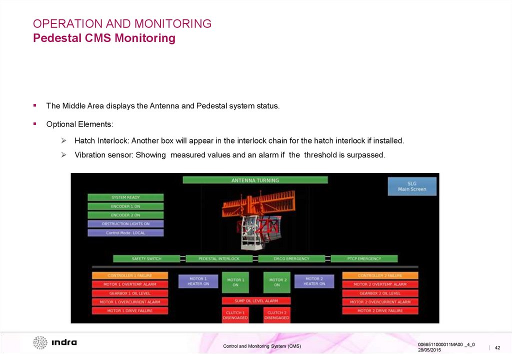
The Middle Area displays the Antenna and Pedestal system status.
Optional Elements:
Hatch Interlock: Another box will appear in the interlock chain for the hatch interlock if installed.
Vibration sensor: Showing measured values and an alarm if the threshold is surpassed.
Control and Monitoring System (CMS)
0066511000011MA00 _4_0
28/05/2015
| 42
43.
OPERATION AND MONITORINGPedestal CMS Operation
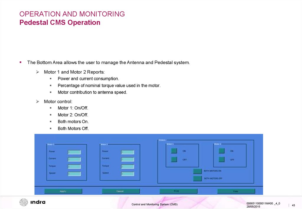
The Bottom Area allows the user to manage the Antenna and Pedestal system.
Motor 1 and Motor 2 Reports:
Power and current consumption.
Percentage of nominal torque value used in the motor.
Motor contribution to antenna speed.
Motor control:
Motor 1: On/Off.
Motor 2: On/Off.
Both motors On.
Both Motors Off.
Control and Monitoring System (CMS)
0066511000011MA00 _4_0
28/05/2015
| 43
44.
IndraSVI - TGP
Ctra. de Loeches, 9
28850 Torrejón de Ardoz,
Madrid - Spain
T +34 91 627 10 00
www.indra.es