


 marketing
Similar presentations:


")


Tube Bundle Frame Report
1.
Root Cause Analysis (Tube Bundle)2.
Tube Bundles Progress ReportTube
#119
bundle No
Joint #
16
Location
#104
#110
#107
#98
#113
15
14
13
12
11
3910 km
1560 km
Smolino Smolino
Distance to
7960 km 7960 km
Nogliki
Vkhodnaya Zalari
6960 km
4760 km
#97
#96
#92
#100
10
9
8
7
4
Komsomol’
Birobidzha
Kharagun
sk-onVanino Vanino Vanino Poronaysk
n
Amur
Dispatched – 16 tube bundles; In transit – 11; Arrived
in Nogliki – 4 & Delivered at OPFC – 1
2
#103
1060 km
785 km 785 km 785 km 325 km
3.
Tube Bundle Package TypeInitial Method of Packing
Section (Tube bundles)
Packing Type: Metal Frame
The upper and lower row of finned tubes
is covered with plywood with a thickness
of at least 10 mm.
The packaging of the tube bundle is
wrapped with heavy duty polyethylene
tape N2 purged on the top and sides.
Revised Method of Packing
3
BHM made variations in tube bundle
packing, only top protection provided. As
well, BHM removed plywood sheets from
the bottom of frame.
4.
Tube Bundle Frame DesignTube Bundle Frame consists
of 5 C-channel supports
On Picture highlighted the
current design of tube bundle
frame
Flaws:
- Missing transversal beams
No. 1 and 5 in frame over
the support beams and in
the lashing points to
distribute the weight.
-
No 100% overlap: C-Chanel
frame shorter than C-Chanel
of support
FRAME
SUPPORT
4
No transversal
beams over
supports to distribute
the weight
No 100% overlap:
C-Chanel frame
shorter than CChanel of support
5.
Experience with BHM related to transport worthy packingCargo solidity
In order to perform safe road
and rail transport the cargo
package shall be sufficiently
lashed in accordance with
respective mode of
transport regulations and
technical conditions to avoid
any shifts and/or movements
under normal transport
process
Cargo inside the package
shall be securely placed to
avoid any movements
inside the package.
Package elements shall
undergo structural analysis
to prove it can withstand
normative forces applicable to
the package during the
transport.
For rail transport lashing
and dunnage calculations
is responsibility of the
carrier (Railway Ministry),
cargo solidity – is
responsibility of
manufacturer and shipper
(BHM)
5
Cases reported on inadequate package
Package A-070-153
Package arrived to Saratov terminal with the cargo visibly damaged. Packages itself
remained firmly lashed and did not move during the road transport. The wall sheets were
not properly secured against transversal and longitudinal movements. Package shipped
back to BHM and package design was re-worked by BHM
Package A-070-113
Package arrived to Saratov terminal. Upon
inspection with rail authorities the questions were
raised whether current securing of the cargo inside
the frame is sufficient. Kerry addressed the issue to
BHM asking to re-check the calculations. Upon
rechecking package was deemed not transport
worthy and shipped back to BHM. package design
was re-worked by BHM before shipping.
6.
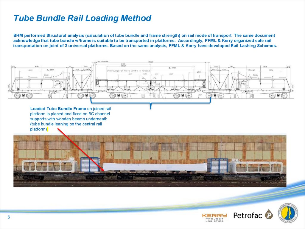
Tube Bundle Rail Loading MethodBHM performed Structural analysis (calculation of tube bundle and frame strength) on rail mode of transport. The same document
acknowledge that tube bundle w/frame is suitable to be transported in platforms. Accordingly, PFML & Kerry organized safe rail
transportation on joint of 3 universal platforms. Based on the same analysis, PFML & Kerry have developed Rail Lashing Schemes.
Type of Rail Car
Internal Dims – Length x Width, mm
13-401
13400 х 2870
For Box drawing No. А-070-202.00.00.000 - 1 standard platform will be required
Loaded Tube Bundle Frame on joined rail
platform is placed and fixed on 5C channel
supports with wooden beams underneath
(tube bundle leaning on the central rail
platform)
6
.
7.
Structural analysis (calculation of tube bundle and frame strength)Conclusion of structural analysis given by
BHM that tube bundle w/frame can be
transported by rail transport
7
8.
Loading and Lashing Schemes ProcessLoading and Lashing scheme development for rail transport
Kerry
suggestions
regarding rail
transport
BHM tube bundle
package design
BHM presents
package design
suitable for rail and
road transport that
satisfies requirements
of the solidity of the
cargo
Kerry presents:
- Request to verify
feasibility of support
beams’ positioning within
13.2m;
- suggestion regarding
adding lashing points for
rail;
- request for calculations
necessary for loading
scheme development
BHM design
amendments,
tube bundle
calculations
BHM confirms
feasibility with
calculation, amends
final package design
adding lashing points
and placing the
supports. The package
remains suitable for rail
and road, provides
calculations necessary
for rail transport.
Kerry loading
and lashing
scheme design
Kerry provides loading
and lashing scheme in
accordance with
technical conditions
(TU-CM943) for BHM
review and
acceptance
BHM review of
feasibility,
signing
BHM reviews the
scheme for
implementation (acts
as lashing service
provider) and signs
the schemes as
Shipper in the rail
process
Railway review
of the loading
and lashing
scheme
Kerry submits
schemes for Railway
review and approval.
Railway examine
only lashing and
dunnage calculation.
Cargo solidity is
BHM responsibility.
Approved
scheme
submitted to
BHM
Accomplished exercise
Approved scheme
Loading and Lashing scheme development for road transport
BHM tube bundle package design
including the frames
BHM presents package
design suitable for rail
and road transport that
satisfies requirements of
the solidity of the cargo
Kerry to provide
intended transport,
loading scheme
design
Based on road transport
availability, Kerry requests to
verify feasibility of transport
on 4 support beams (#1,3,4
and 5); provides draft lashing
scheme
The same was utilized, see the
next slide
8
BHM to verify and
confirm suitability of
Transport design vs.
TB Structure integrity
Kerry loading and
lashing scheme design
finalization
Kerry to obtain
Transport permit from
relevant authorities.
/Transport Agency
permit
BHM confirms feasibility with
calculation, suggests adding 4
additional transport belts to
protect cargo from longitudinal
movements
Kerry finalizes loading and
lashing scheme based on
BHM input and provides it to
the carriers for review and
approval
Carrier submits the scheme
and other documents for
obtaining ODC road permit to
Governmental Control Body
OOG road permit
Accomplished exercise
ODC permit
endorsement
9.
Transshipment operations in Nogliki & Damage ReportTransshipment of Tube Bundle No.93 onto extendable Trailer. Scheme Below
Loading date on 09.12.2020
Arrival to OPFC on 10.12.2020.
Upon transshipment operations of tube bundle in Nogliki, adequate
means of transport was utilized, lashing in compliance with BHM
guideline and Structural analysis (calculation) performed earlier by BHM
on 4 support beams.
It demonstrated on road scheme 4 support beams are acceptable to
proceed road transportation. In accordance with comments made the
final scheme features 8 belts to protect the cargo against longitude
movements.
Photo
9
10.
Damage ReportRoot cause (hypothesis):
Full weight of the tube bundle frame is distributed on the
supports’ short side of the C-Chanel
Short side C-Chanel receives excess bending force under
transport movement
Short side C-Chanel cracks and then collapses dragging
tube bundle down.
Collapse of tube bundle on the right side of loading frame
support created excessive pressure on the bolts left side
which resulted cracks
Tube bundle #93 support
#1 damage
Route cause hypothesis:
-
10
-
There are no transversal beams to distribute tube bundle frame load on the
supports;
Support design relies only on bending stress, not on bearing stress;
C-shape channel does not function properly due to lack of 100% overlap;
11.
Visual Inspection of tube bundle # 102 on rail platformsInspection
Upon the notification of the incident, visual inspection arranged in r/w Nogliki:
Visual inspection of 2 other tube bundles #95 and #101 were conducted;
Tube bundles #94 and #102 supports were closely inspected on the
wagons (arrival on 11.12.2020) in order to eliminate possibility of
mishandling in Nogliki
Tube bundle #102 support #1 prior to discharge
Visual inspection results: 3 of 4 tube bundles have cracks in the support #1
and C-Chanel bends in other supports
Tube bundle #101 support #1
Tube bundle #95 support #1
Kerry have visually inspected part of the support beam and found cracks in the transport
frame beams (as shown in the pictures).
Condition of Tube bundle in finding on any damages (if occurred) without removal of shrink
wrap not possible, Kerry will organize visual inspection in few days time (if requested by BHM
11 & PFML)
Tube bundle #93
support #1 damage
12.
Recovery PlanSafe transport of the not yet
shipped tube bundles
1. Suspension of loading & dispatch
operations of tube bundles until BHM
will re-visit structural analysis
(calculations) Reinforcement of the
supports and additional structural
analysis
a. Reinforcement plates
welding (see below)
b. Reinforcement backbone
welding (see below)
c. Additional Transversal
beams in transport frame
Safe transport of the tube bundles
in transit
1. Immediate structural analysis of the
supports and evaluation of its results in
comparison to technical conditions of
Railway acceptance.
2. Rail dispatch to be suspended till
calculation to be verified by BHM and if
necessary, changes in current design of
the beam
3. Road transport scheme overhaul
a. Reinforcement of the supports
b. Use of wooden beams supports
lean on the frame (see below
scheme)
Road transport with wooden beams option 3b.
a.
12
b.
Safe transport of the damaged tube
bundle to repair shop (proposed by
Kerry)
1. Tube bundle condition evaluation
2. Development of the dedicated transport
plan
3. Road transport is preferable with shorter
transit time and less risk of damage in
transit.
4. Timeline for transport preparation:
a. Evaluation of transport
conditions 5 days
b. Development of transport
supports and transportation
scheme, route survey 15-20
days
c. Transit time 25-30 days
d. Backload Transit time 25-30
days.