


 industry
Similar presentations:


Fuel system
1.
FUELMENU
System Presentation
1/35
2.
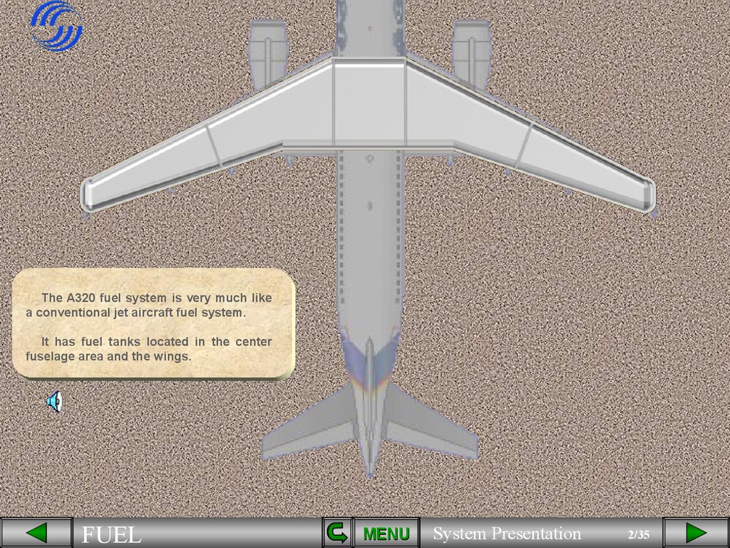
The A320 fuel system is very much likea conventional jet aircraft fuel system.
It has fuel tanks located in the center
fuselage area and the wings.
FUEL
MENU
System Presentation
2/35
3.
FUELMENU
System Presentation
3/35
4.
FUELMENU
System Presentation
4/35
5.
FUELMENU
System Presentation
5/35
6.
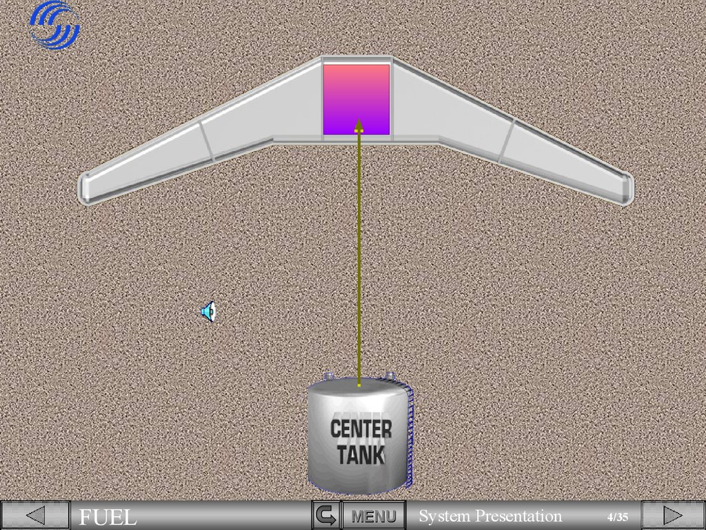
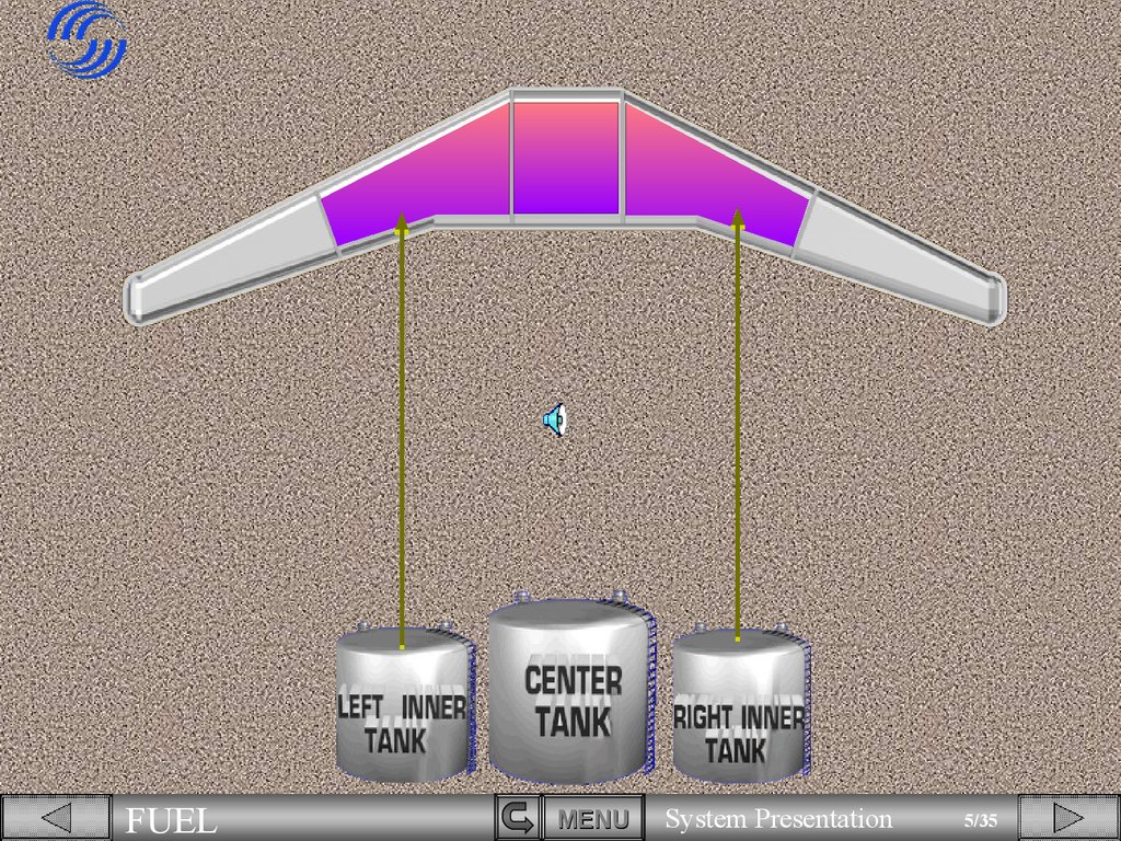
The center tank is located in the fuselage.The inner tanks are located in the wings.
and the outer tanks are located in the
wings.
FUEL
MENU
System Presentation
6/35
7.
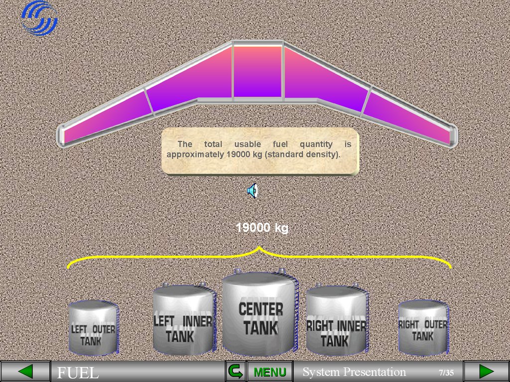
The total usable fuel quantity isapproximately 19000 kg (standard density).
19000 kg
FUEL
MENU
System Presentation
7/35
8.
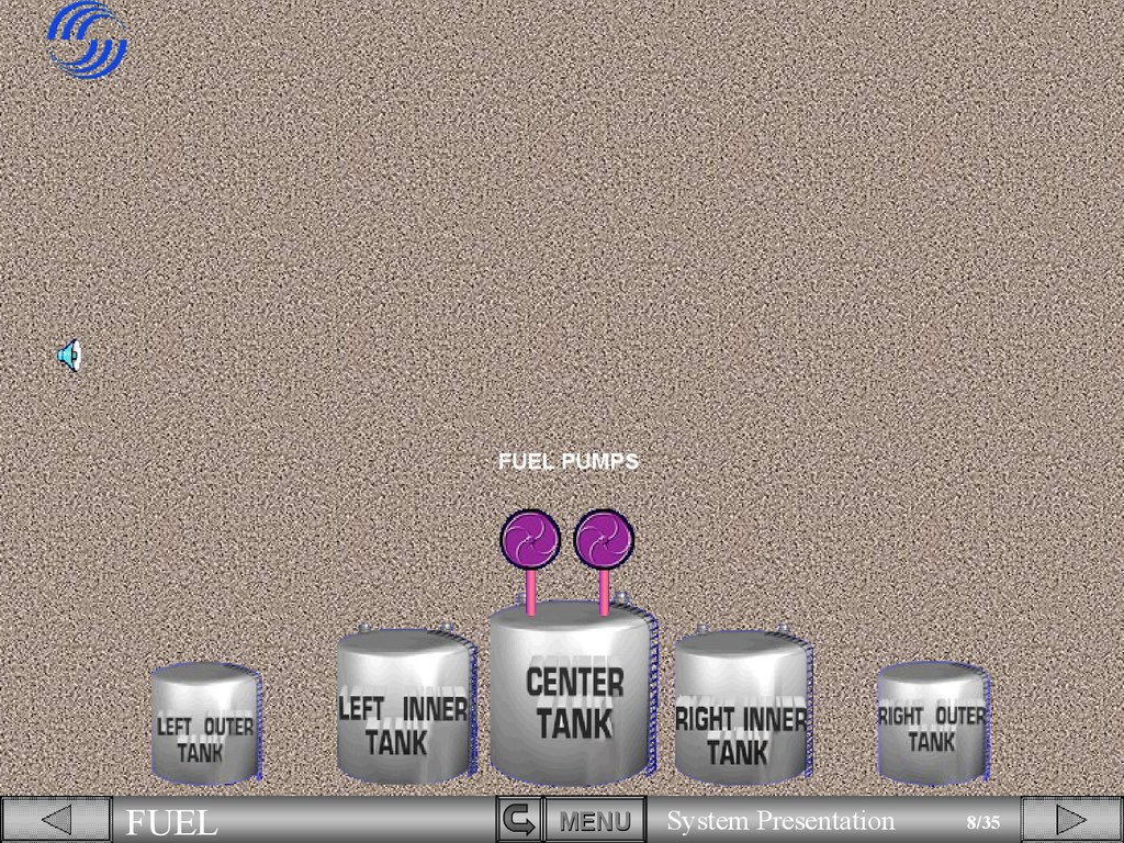
FUEL PUMPSFUEL
MENU
System Presentation
8/35
9.
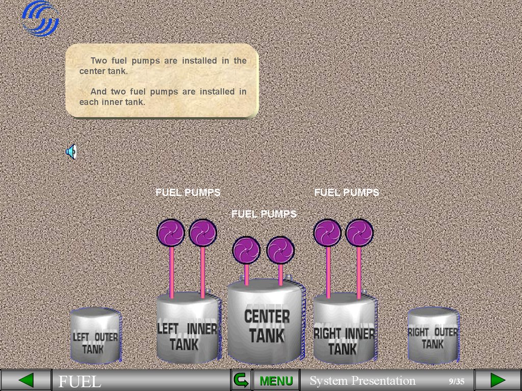
Two fuel pumps are installed in thecenter tank.
And two fuel pumps are installed in
each inner tank.
FUEL PUMPS
FUEL PUMPS
FUEL PUMPS
FUEL
MENU
System Presentation
9/35
10.
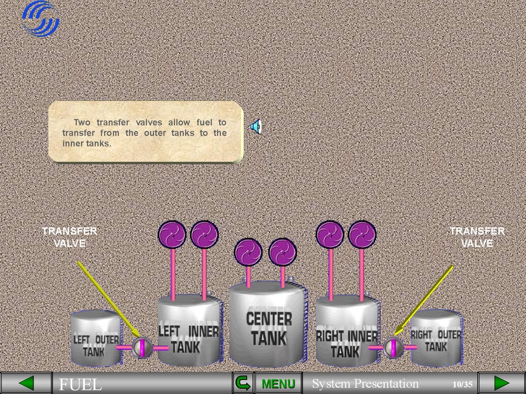
Two transfer valves allow fuel totransfer from the outer tanks to the
inner tanks.
TRANSFER
VALVE
FUEL
TRANSFER
VALVE
MENU
System Presentation
10/35
11.
ENG 1FUEL
ENG 2
MENU
System Presentation
11/35
12.
ENG 1ENG 2
ENGINE
LP VALVE
ENGINE
LP VALVE
Each inner tank feeds
its respective engine.
Two
engine
Low
Pressure valves are
installed to cut off fuel
to the engines.
FUEL
MENU
System Presentation
12/35
13.
ENG 1FUEL
ENG 2
MENU
System Presentation
13/35
14.
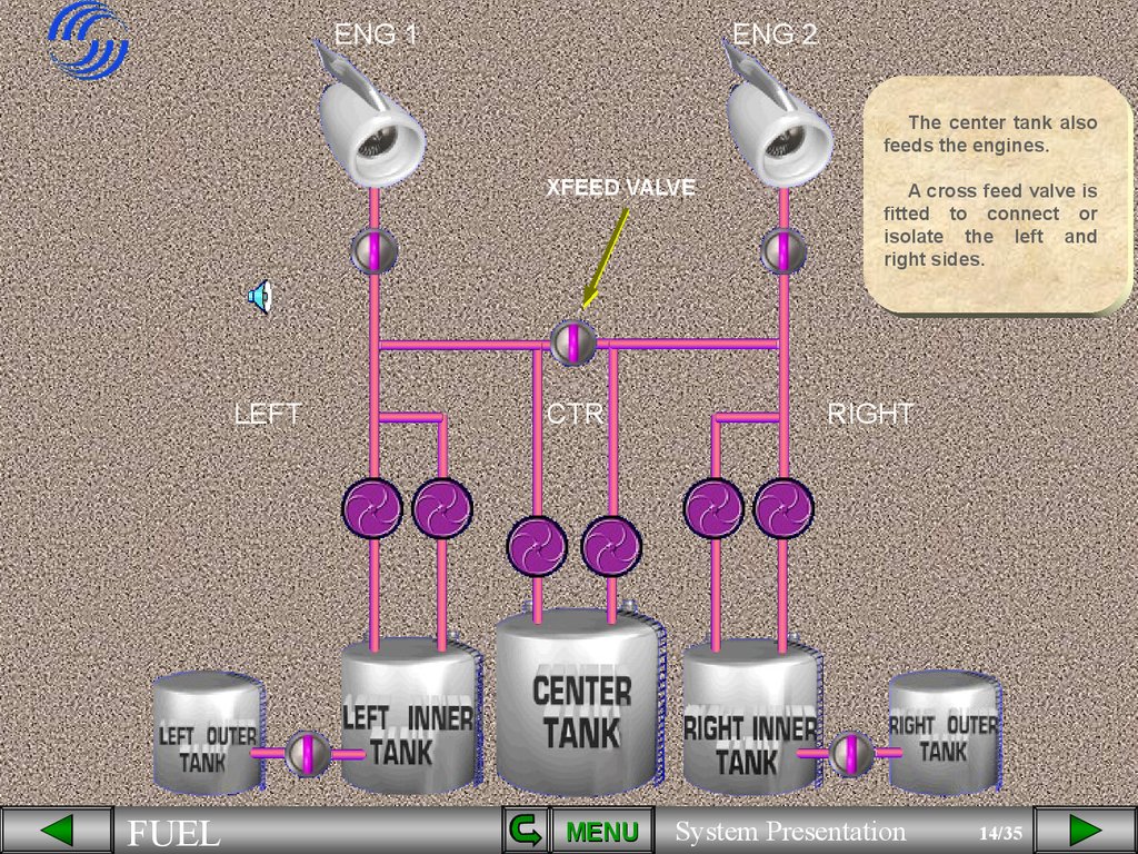
ENG 1ENG 2
The center tank also
feeds the engines.
XFEED VALVE
LEFT
FUEL
CTR
MENU
A cross feed valve is
fitted to connect or
isolate the left and
right sides.
RIGHT
System Presentation
14/35
15.
ENG 1ENG 2
APU
LEFT
FUEL
CTR
MENU
RIGHT
System Presentation
15/35
16.
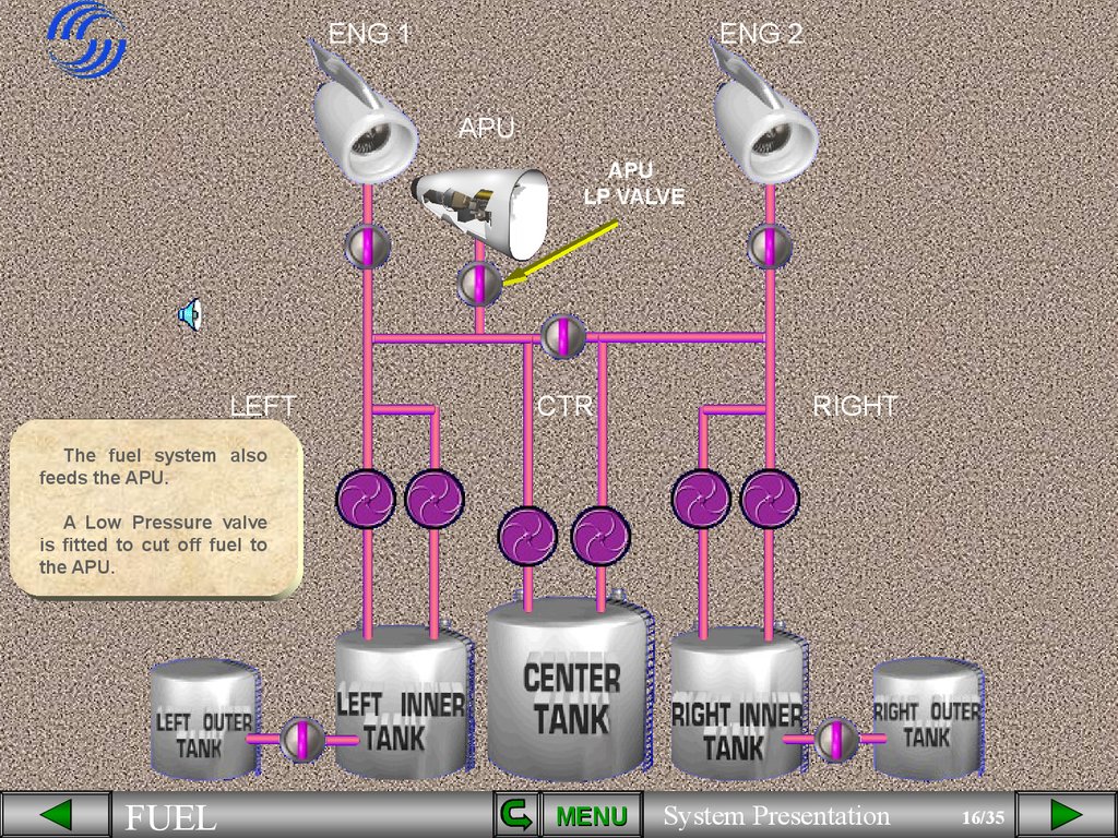
ENG 1ENG 2
APU
APU
LP VALVE
LEFT
CTR
RIGHT
The fuel system also
feeds the APU.
A Low Pressure valve
is fitted to cut off fuel to
the APU.
FUEL
MENU
System Presentation
16/35
17.
ENG 1ENG 2
APU
LEFT
CTR
RIGHT
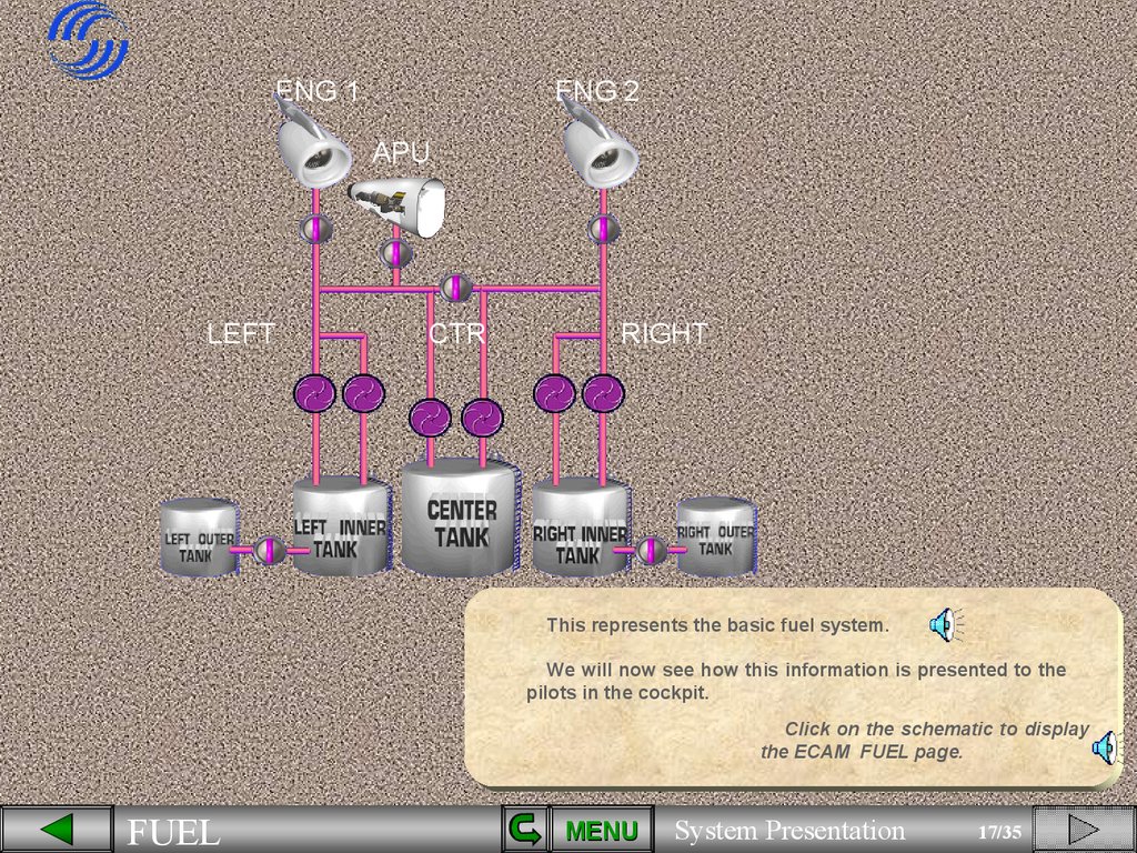
This represents the basic fuel system.
We will now see how this information is presented to the
pilots in the cockpit.
Click on the schematic to display
the ECAM FUEL page.
FUEL
MENU
System Presentation
17/35
18.
ENG 1ENG 2
APU
LEFT
CTR
RIGHT
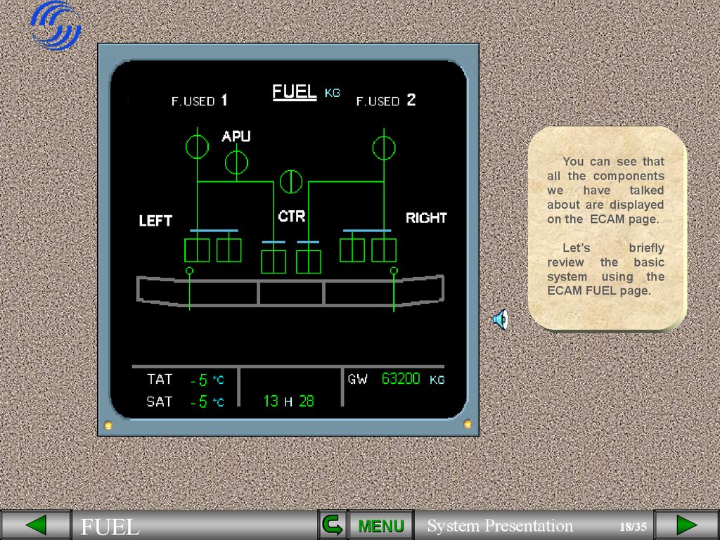
You can see that
all the components
we
have
talked
about are displayed
on the ECAM page.
Let’s
briefly
review the basic
system using the
ECAM FUEL page.
FUEL
MENU
System Presentation
18/35
19.
• The center tank in thefuselage,
• the inner tanks in the
wings,
• the outer tanks in the
wings,
FUEL
MENU
System Presentation
19/35
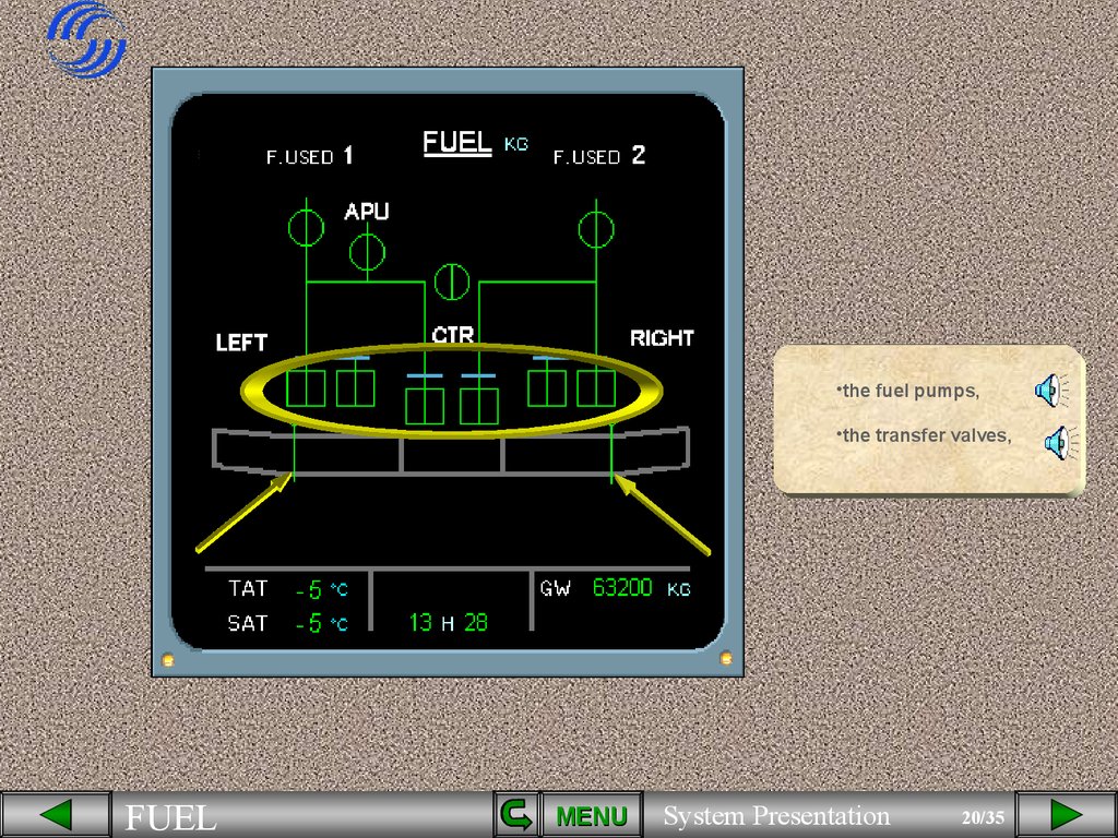
20.
•the fuel pumps,•the transfer valves,
FUEL
MENU
System Presentation
20/35
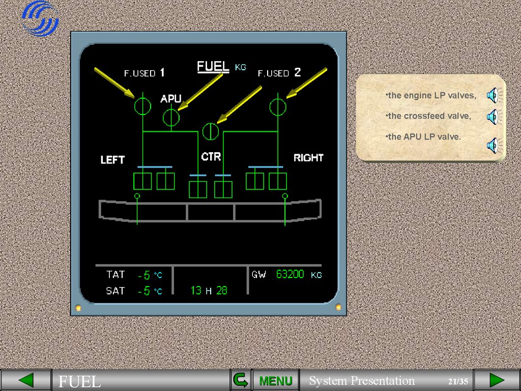
21.
•the engine LP valves,•the crossfeed valve,
•the APU LP valve.
FUEL
MENU
System Presentation
21/35
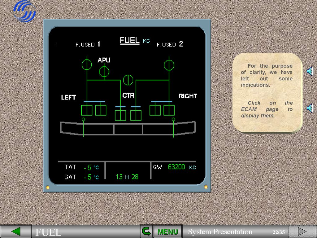
22.
For the purposeof clarity, we have
left
out
some
indications.
Click
on
ECAM
page
display them.
FUEL
MENU
System Presentation
22/35
the
to
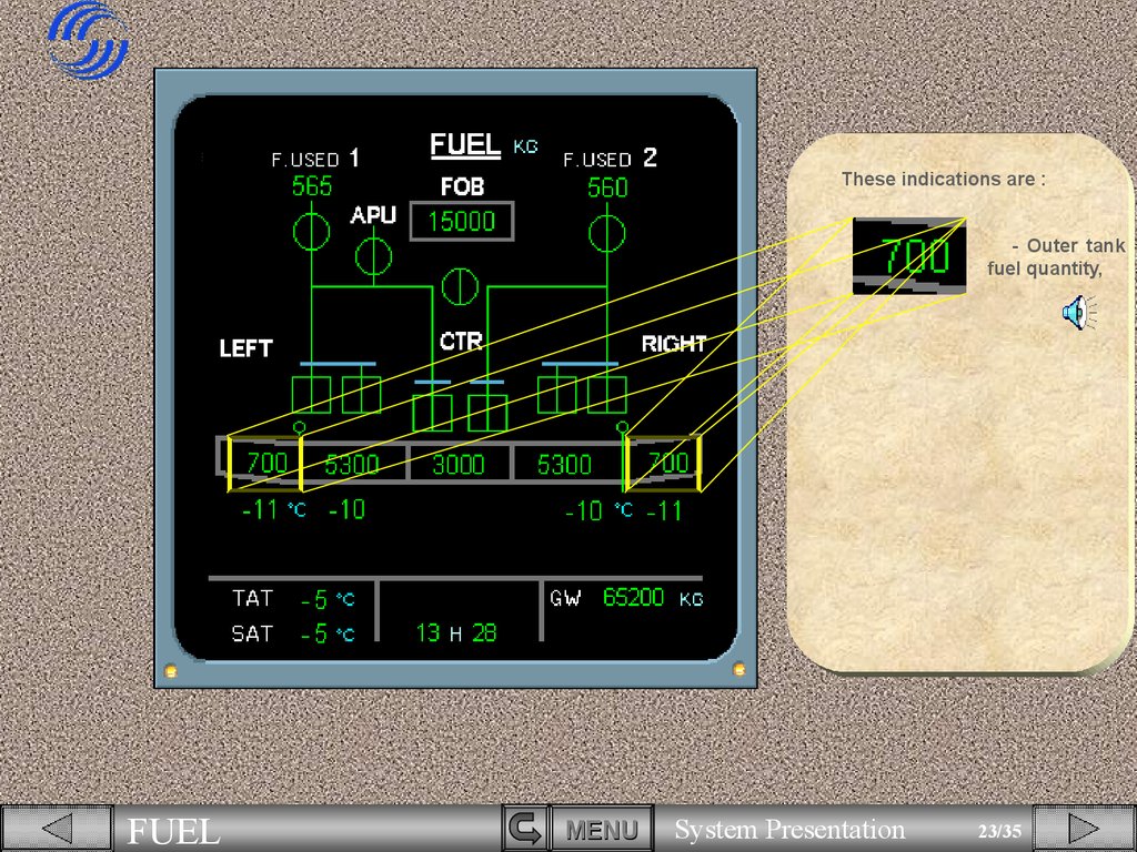
23.
These indications are :- Outer tank
fuel quantity,
FUEL
MENU
System Presentation
23/35
24.
These indications are :- Outer tank
fuel quantity,
- inner tank
fuel quantity,
FUEL
MENU
System Presentation
24/35
25.
These indications are :- Outer tank
fuel quantity,
- inner tank
fuel quantity,
- center tank
fuel quantity,
FUEL
MENU
System Presentation
25/35
26.
- Fuel OnBoard (FOB),
FUEL
MENU
System Presentation
26/35
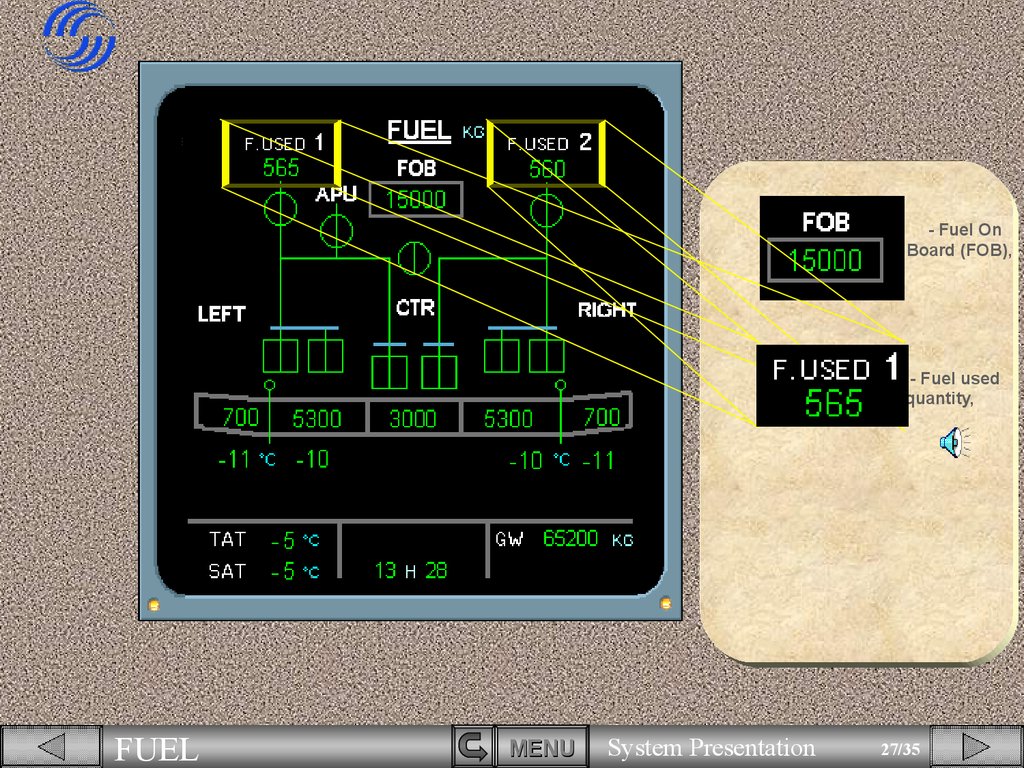
27.
- Fuel OnBoard (FOB),
- Fuel used
quantity,
FUEL
MENU
System Presentation
27/35
28.
- Fuel OnBoard (FOB),
- Fuel used
quantity,
- Outer tank
temperature,
FUEL
MENU
System Presentation
28/35
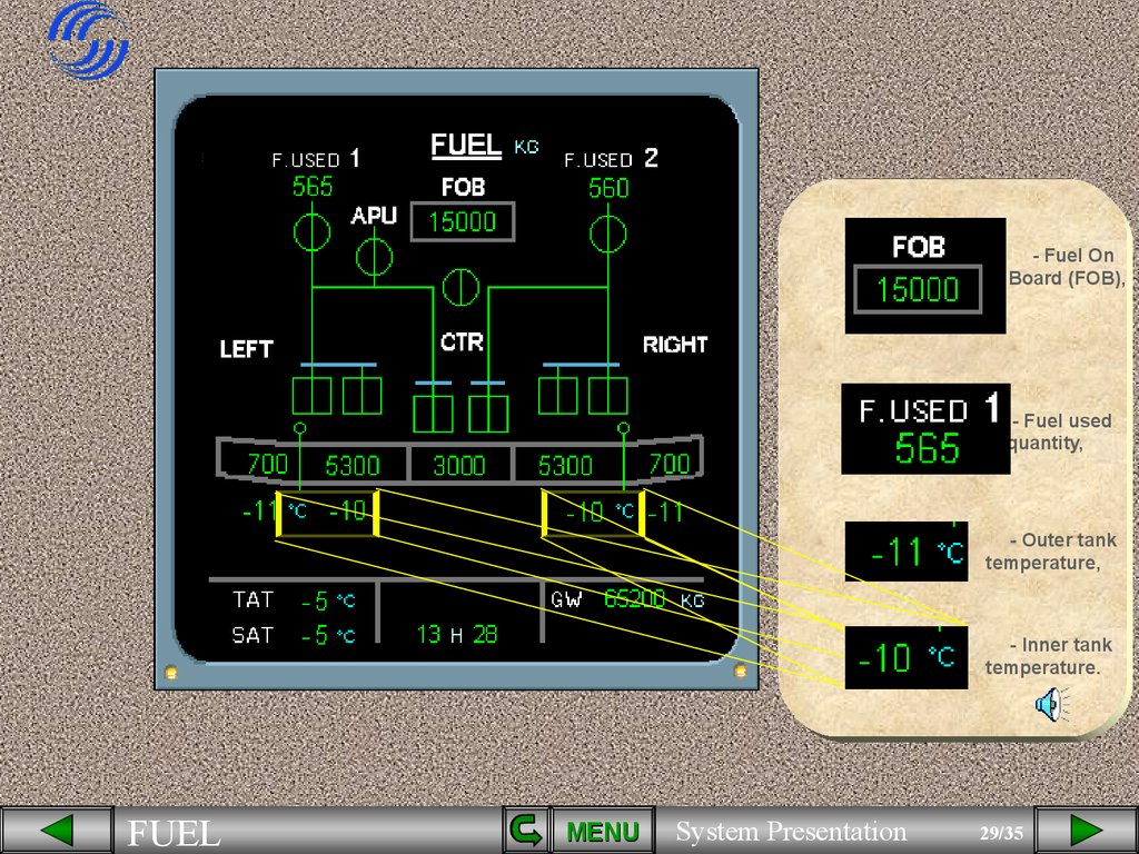
29.
- Fuel OnBoard (FOB),
- Fuel used
quantity,
- Outer tank
temperature,
- Inner tank
temperature.
FUEL
MENU
System Presentation
29/35
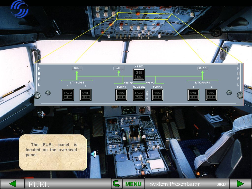
30.
The FUEL panel islocated on the overhead
panel.
FUEL
MENU
System Presentation
30/35
31.
Each wing tank pumpis controlled by its
associated pb sw on the
FUEL panel.
FUEL
MENU
System Presentation
31/35
32.
Eachcenter
tank
pump is controlled by its
respective pb sw.
FUEL
MENU
System Presentation
32/35
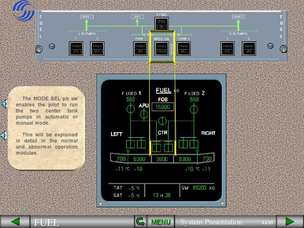
33.
The MODE SEL pb swenables the pilot to run
the two center tank
pumps in automatic or
manual mode.
This will be explained
in detail in the normal
and abnormal operation
modules.
FUEL
MENU
System Presentation
33/35
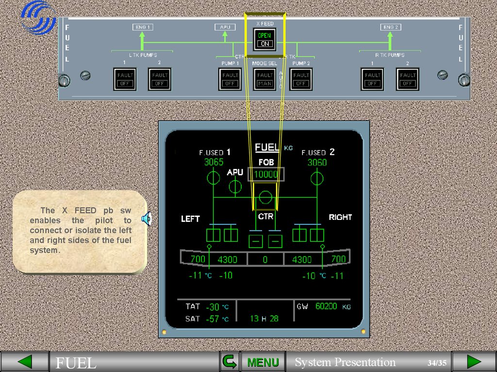
34.
The X FEED pb swenables the pilot to
connect or isolate the left
and right sides of the fuel
system.
FUEL
MENU
System Presentation
34/35
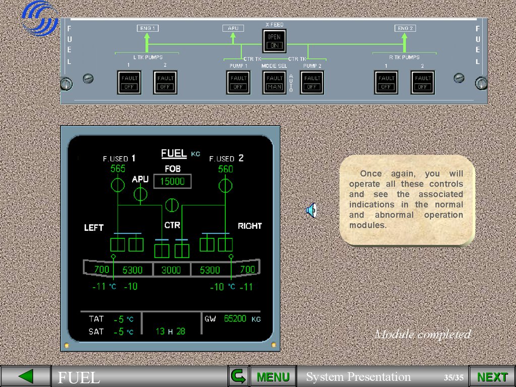
35.
Once again, you willoperate all these controls
and see the associated
indications in the normal
and abnormal operation
modules.
Module completed
FUEL
MENU
System Presentation
35/35
NEXT
36.
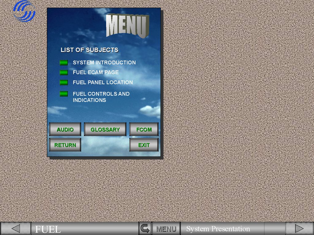
LIST OF SUBJECTSSYSTEM INTRODUCTION
FUEL ECAM PAGE
FUEL PANEL LOCATION
FUEL CONTROLS AND
INDICATIONS
AUDIO
RETURN
FUEL
GLOSSARY
FCOM
EXIT
MENU
System Presentation
36/35