


 mathematics
Similar presentations:


")


Computation on arbitrary surfaces
1. Computation on Arbitrary Surfaces
Brandon LloydCOMP 258
October 2002
1
2. Computation on Arbitrary Surfaces
• Mathematical framework for Euclideangeometry enables us to perform important
operations
• Usually peformed on regular grid
• Triangle meshes have irregular connectivity,
hence irregular sampling
• Triangle meshes are general 2-manifolds
2
3. Computation on Arbitrary Surfaces
• Displaced Subdivision Surfaces• Multi-resolution signal processing on meshes
• Texture synthesis on meshes
3
4. Displaced Subdivision Surfaces
• Aaron Lee, Henry Moreton and Hughes Hoppein SIGGRAPH 2000.
• The idea is to use a scalar-valued
displacement over a smooth domain mesh
Control mesh
Smooth domain
surface
Displaced
subdivision surface
4
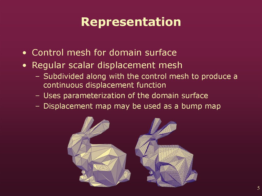
5.
Representation• Control mesh for domain surface
• Regular scalar displacement mesh
– Subdivided along with the control mesh to produce a
continuous displacement function
– Uses parameterization of the domain surface
– Displacement map may be used as a bump map
5
6. Conversion Process
• Obtain the controlmesh
• Optimize the control
mesh to more closely
resemble original
Original mesh
Displaced subdivision
surface
• Sample displacement
map
6
7. Simplifying the Control Mesh
• Done with edge collapses• Map vertex normals from neighborhood of
candidate edge collapse to Gauss sphere
• Disallow collapse if original normals are not
enclosed in spherical triangle
7
8. Optimizing the Domain Surface
Initial controlmesh
Optimized control
mesh
• Move vertices of
control mesh to
more accurately fit
the original mesh
• Densely sample
original mesh and
minimize least
squared distances
• Affects normals, but
does not produce
noticeable problems
8
9. Sampling the Displacement Map
SubdividedDomain surface
Displacement
field
• Perform subdivision
on optimized control
mesh
• Intersect ray formed
by point and normal
with original mesh
• Store distance in
displacement map
9
10. Applications
• Compression – Thedisplacement map
contains small,
similar values
• Editing – simply
modify the scalar
field
• Animation – easier
to kinematics with
control mesh
10
11. Compression Results
1112. Burt-Adelson Pyramids
2• Prefilter and downsample
image Ln to produce Ln-1
12
13. Burt-Adelson Pyramids
22
• Prefilter and downsample
image Ln to produce Ln-1
• Upsample Ln-1 and
subtract from Ln
13
14. Burt-Adelson Pyramids
22
• Prefilter and downsample
image Ln to produce Ln-1
• Upsample Ln-1 and
subtract from Ln
• Repeat till you reach L0
14
15. Burt-Adelson Pyramids
22
• Prefilter and downsample
image Ln to produce Ln-1
• Upsample Ln-1 and
subtract from Ln
• Repeat till you reach L0
• The result is an image
pyramid with a frequency
subband at each level
15
16. Multiresolution Signal Processing for Meshes
• Igor Guskov, Wim Sweldens and PeterSchröder in SIGGRAPH 1999.
• Generalizes basic signal processing tools such
as downsampling, upsampling, and filters to
irregular triangle meshes
• Uses a non-uniform relaxation procedure for
geometric smoothing
• Smoothing combined with hierarchical
algorithms are used to build subdivision and
pyramid methods
16
17. Importance of Smoothness
• Geometric smoothness measures variance intriangle normals.
• Geometric smoothness implies that there
exists a smooth (differentiable)
parameterization for the mesh
• Smooth parameterization is important for
many algorithms
17
18. Importance of Smoothness
• Refinement can use semi-uniform (weightsdepend only on local connectivity) subdivision
to obtain geometric smoothness
• It is much harder if we want to coarsify a
mesh and later refine it again.
• Forced to use non-uniform (weights depend on
connectivity and geometry) subdivision.
• The challenge is to ensure smooth local
parameterization.
18
19. Divided Differences
• First order divided difference of g(u,v) withdiscrete gi at the vertices is the gradient:
• The normal to the triangles formed by vertices
is given by:
• Second order differences are the the
difference between two normals on
neighboring triangles. Only the magnitude
matters.
19
20. Divided Differences
2021. Divided Differences
• The magnitude of the second divideddifference over edge e is:
• With coefficients
21
22. Relaxation Procedure
• The relaxation operator R minimizes secondorder differences over a small neighborhood
• Define R as the minimizer of a quadratic
energy function E:
• Expand in terms of gi:
2
22
23. Relaxation Procedure
• Set the partial derivative of E with respect togi to zero and solve:
• Relaxation for geometry use vertices pi in
place of gi
• For each divided difference use the hinge map
is use for local parameterization. Rotate
triangles about their common edge till they lie
in the same plane
23
24. Relaxation Procedure
• This non-uniform smoothing operator does notaffect triangle shapes much because it takes
geometry into account.
• A semi-uniform scheme makes edge lengths
as uniform as possible and distorts the mesh
Original mesh
Semi-uniform
smoothing
Non-uniform
smoothing
24
25. Upsampling and Downsampling
• Uses Hoppe’s Progressive Mesh (PM)approach
• Vertex split provides upsampling
• Edge collapse provides
downsampling
• Different than most multi-resolution
schemes where downsampling
removes a fraction of the samples
25
26. Subdivision
• Starts from a coarse mesh and builds finer,smoother mesh
• Can be viewed as upsampling followed by
relaxation
• Coarse mesh comes from PM.
• The goal is to start from coarse mesh and
produce a smooth mesh with same
connectivity as original with as little distortion
as possible
• Performed one vertex at a time
26
27. Subdivision
• The non-uniformscheme has access
to parameterization
info of the original
mesh which guides
the subdivision to
give the desired
result
27
28. Building a Pyramid
• Downsampling: vertex n is removed by anedge collapse
• Subdivision: Points affected by the edge
collapse are subdivided
• Detail Computation: Differences between
points before edge collapse and after
subdivision are stored
28
29. Smoothing and Filtering
• The details from thepyramid are an
approximate frequency
spectrum
• Scale details for various
filtering effects
29
30. Smoothing and Filtering
• The details from thepyramid are an
approximate frequency
spectrum
• Scale details for various
filtering effects
• Smoothing does not
mess up texture
mapping!
30
31. Enhancement
• Single resolution scheme– Smooth mesh a number
of times
– Extrapolate differences
between smoothed and
original mesh
31
32. Enhancement
• Single resolution scheme– Smooth mesh a number
of times
– Extrapolate differences
between smoothed and
original mesh
• Multi-resolution scheme
– Scale details with values
greater than 1
32
33. Multiresolution Editing
• User manipulates vertices at a level in thepyramid and system adds finer details back in
• Details are defined with respect to local
frames
Original
Coarsest
Coarsest
edit
Multi-res Single-res
reconst.
reconst.
33
34. Texture Synthesis on Surfaces
• Paper by Greg Turk, SIGGRAPH 2001• Motivation
– Texture greatly improves appearance
– The ideal system is texture-from-sample
– Existing texture synthesis operates on 2D
grids
– It is difficult to map 2D texture
– It is not always possible to use 3D texture
34
35. Texture Synthesis on Surfaces
• Solution = Synthesize texture directlyon a mesh.
35
36. Texture Synthesis Algorithm
• Based on work by Weiand Levoy [Wei00]
• Initialize destination
image to white noise
• Process pixels in raster
scan order
• Find best match for
neighborhood in original
image
• Replace pixel in
destination with pixel
from original image
36
37. Texture Synthesis Algorithm
Full 5x5 neighborhood1 Level
2 Levels
• Use multi-resolution to
get a full neighborhood.
• Create an image pyramid
• Start at the top of the
pyramid
• Use data from higher
levels to fill in
unprocessed pixels in full
neighborhood
• Multi-resolution improves
quality
3 Levels
37
38. Creating the Mesh Hierarchy
• Place uniform randompoints on the surface of
the mesh
– Choose a random
polygon based on area
– Choose a random point
within the polygon
38
39. Creating the Mesh Hierarchy
• Use repulsion forces toget an even distribution
– Map nearby points to a
plane
– Compute forces within
the plane
• Compute Voronoi
diagram to establish
sample connectivity
– Once again map nearby
points to a plane
– Compute diagram within
the plane
• Details in [Turk91]
39
40. Creating the Mesh Hierarchy
• Start by placing n pointson the mesh
• Add an additional 3n
points and repel them
from themselves and
original n
• Create a new mesh
including all 4n points
• Repeat to create several
levels
40
41. Operations on Mesh Hierarchy
• Interpolation• Low-pass filtering
• Downsampling
• Upsampling
41
42. Operations on Mesh Hierarchy: Interpolation
• Take a weighted average of all mesh verticesvi within a particular radius r of point p
• The weighting function causes vertex
contributions to falloff smoothly to 0 as
distance from p approaches r.
42
43. Operations on Mesh Hierarchy: Low-pass Filtering
• Borrow techniques from mesh smoothing tomodify vertex positions. Weights wi are
inverse edge length:
• Similarly for colors of adjacent mesh vertices
43
44. Operations on Mesh Hierarchy: Low-pass Filtering
• Regrouping terms, the expression can besimplified to:
44
45. Operations on Mesh Hierarchy: Upsampling and Downsampling
• Vertices store a color for each level they arein.
• To downsample from mesh Mk the vertices in
the lower resolution mesh Mk+1 inherit the
blurred mesh colors in Mk.
• To upsample from mesh Mk+1, the colors of the
vertices in Mk are interpolated from Mk+1.
45
46. Vector Field Creation
• Vector field is needed to establish orientation• A few vectors are assigned at lowest level. All
others set to zero
• Vectors are “pulled” to coarsest mesh by a
number of downsamplings
• Remaining zero vectors are “filled” by diffusing
vectors over the mesh
• Vectors are “pushed” to lower levels by
repeated upsampling
46
47. Surface Sweeping
• Similar to raster scanning in original algorithm• All vertices are assigned a sweep distance
s(v).
• Anchor vertex has a sweep distance of 0
User-assigned
vectors
Resulting
vector field
Sweep values
47
48. Surface Sweeping
• Calculate an estimate Δw of how much furtherdownstream a vertex is than its assigned
neighbors:
48
49. Surface Sweeping
• Assign a sweep distance using estimates:• Propogate sweep distances over coarsest
mesh
• Assign sweep distances to finer meshes with
upsampling
49
50. Neighborhood Colors
• Neighbor positions are defined as offsets (i,j)from the current sample.
• Local orientation is provided by the vector field
• Step to neighborhood location by marching
along mesh in the direction of the vector field
for i and perpendicular to it for j.
• Each step is the length of the average distance
between vertices
• Retrieve color by interpolation
50
51. Complete Algorithm
5152.
5253. Texture Synthesis over Arbitrary Manifold Surfaces
• Paper by Li-Yi Wei and Marc Levoy also inSIGGRAPH 2001 [WL01]
• Major differences from [Turk01]
– Synthesis ordering – Vertices are visted in random
ordering
– Local coordinate frames
– Neighborhood construction
53
54. Local Coordinate Frames
• Assigned at coarsest level. Finer levelsinterpolate from higher levels.
• Random works well for isotropic textures.
• Relaxation produces n-way symmetry:
54
55. Local Coordinate Frames
Isotropictextures
Anisotropic textures
Random
Spherical Mapping
Relaxed
55
56. Neighborhood Construction
• Local flattening of the mesh and resampling.• Orthographically project neighboring triangles
of a point p into its local plane.
• Grow region until neighborhood template is
fully covered.
56
57. Neighborhood Construction
• For lower-resolution neighborhood, projectparent face intersected by ray from p in the
direction of the normal.
57
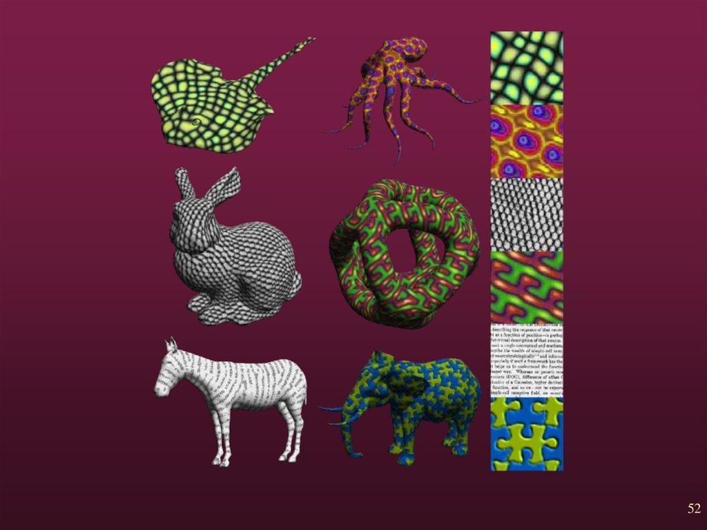
58. Results
5859. References
[GSS99]I. Guskov, W. Sweldens and P. Schröder,
Multiresolution Signal Processing for Meshes,
Proceedings of SIGGRAPH ’99, pp. 325-334, 1999.
[LMH00]
A. Lee, H. Morenton and H. Hoppe. Displaced
Subdivision Surfaces, Proceedings of SIGGRAPH
2000, pp.84-97, 2000.
[Turk91]
G. Turk, Generating Textures for Arbitrary Surfaces
Using Reaction-Diffusion, Proceedings of
SIGGRAPH ’91, pp 289-298, 1991.
[Turk01]
G. Turk, Texture Synthesis on Surfaces, Proceedings
of SIGGRAPH ’01, pp.347-354, 2001.
[WL01]
L. Wei and M. Levoy. Texture Synthesis over
Arbitrary Manifold Surfaces, Proceedings of
SIGGRAPH ’01, pp. 355-360, 2001.
59