


 electronics
Similar presentations:


![PBA Repair Guide [GT-S8000]](https://cf.ppt-online.org/files/thumb/t/tIHBnfpml5G6E47aLocdVU0kDZQNvuejRhAMC8.jpg "PBA Repair Guide [GT-S8000]")


A5 series debug guide
1.
POWERMAXAHE58 DEBUG GUIDE
2.
CHIP RESISTORMARK
ALGORITHM
VALUE
100
10*1
10Ω
201
20*10
200Ω
1000
100*1
100Ω
4701
470*10
4.7KΩ
5R1
5R1=5.1
5.1Ω
51R
51R=51
51Ω
R220
R220=0.22
0.22Ω
R150
R150=0.15
0.15Ω
3.
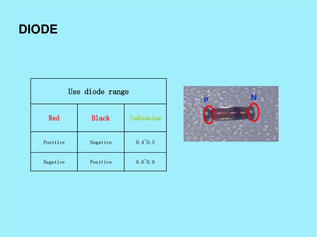
DIODEUse diode range
P
Red
Black
Indication
Positive
Negative
0.4~0.5
Negative
Positive
0.6~0.9
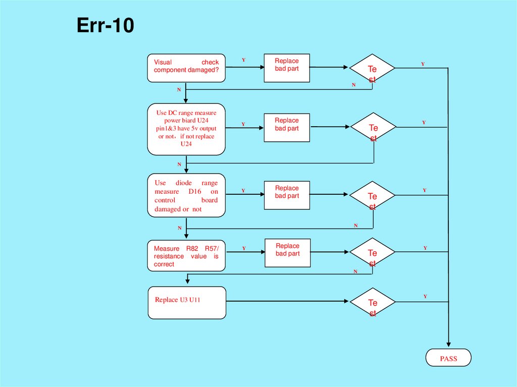
N
4.
Diode bridgeUse diode range
Red
Black
Indication
PIN 3
0.4~0.5
PIN 2
0.4~0.5
PIN 1
0.4~0.5
PIN 4
PIN 2
0.4~0.5
PIN 1
PIN 3
0.4~0.5
5.
IGBTUse diode range
Red
Black
Indication
PIN 2
0.4~0.5
PIN 3
0.6~0.7
PIN 1
6.
IRF530Use diode range
Red
Black
Indication
PIN 2
0.4~0.5
PIN 3
0.6~0.9
PIN 1
7.
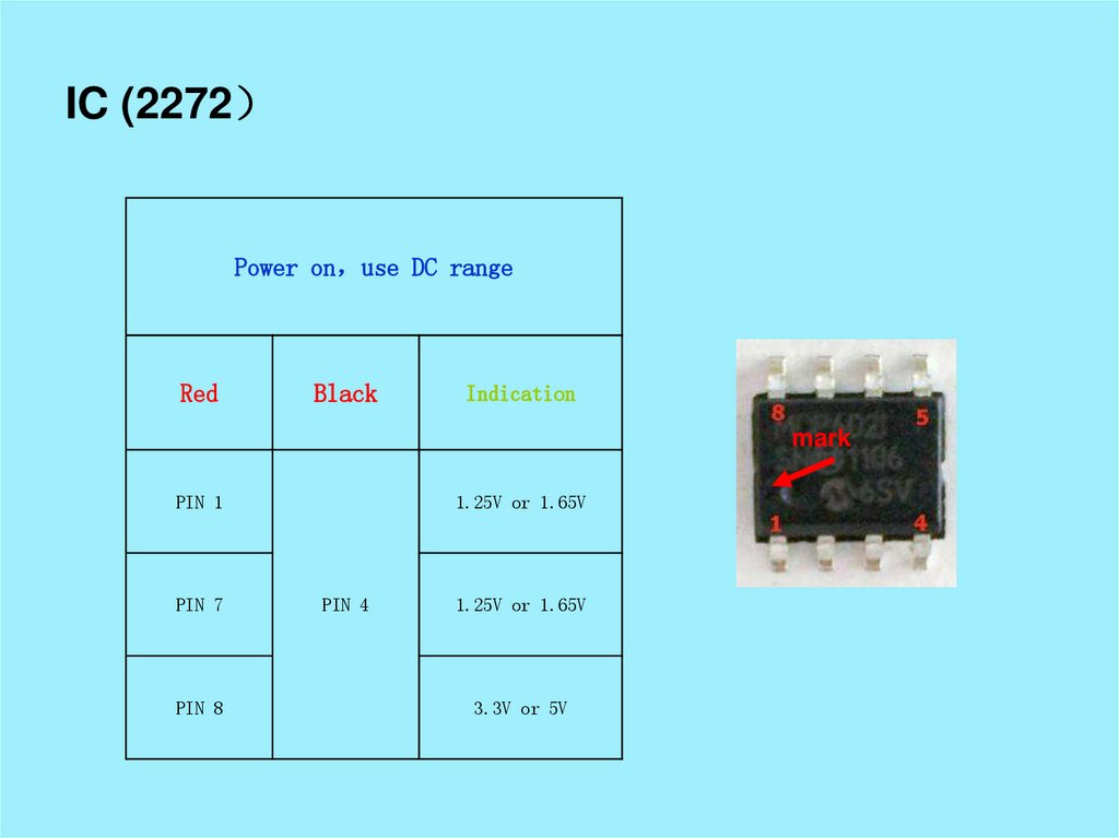
IC (2272Power on use DC range
Red
Black
Indication
mark
PIN 1
PIN 7
PIN 8
1.25V or 1.65V
PIN 4
1.25V or 1.65V
3.3V or 5V
8.
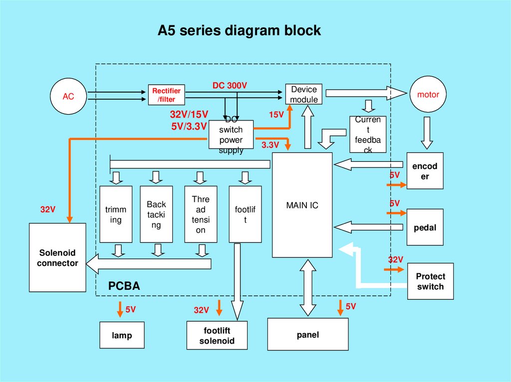
A5 series diagram blockDC 300V
Rectifier
/filter
AC
32V/15V
5V/3.3V
DC
switch
power
supply
Device
module
15V
motor
Curren
t
feedba
ck
3.3V
5V
32V
trimm
ing
Back
tacki
ng
Thre
ad
tensi
on
footlif
t
encod
er
5V
MAIN IC
pedal
Solenoid
connector
32V
Protect
switch
PCBA
5V
lamp
5V
32V
footlift
solenoid
panel
9.
AHE5810.
POWER SUPPLY BLOCKAC 220V
rectifier/filter
DC 300V
Switch Power Supply
DC 15V
U10(7815)
To
control
IC
DC 5V
U27(7805)
To CHIP
IC
DC 5V
U24(7805)
To
Panel
DC 32V
To
solenoid
11.
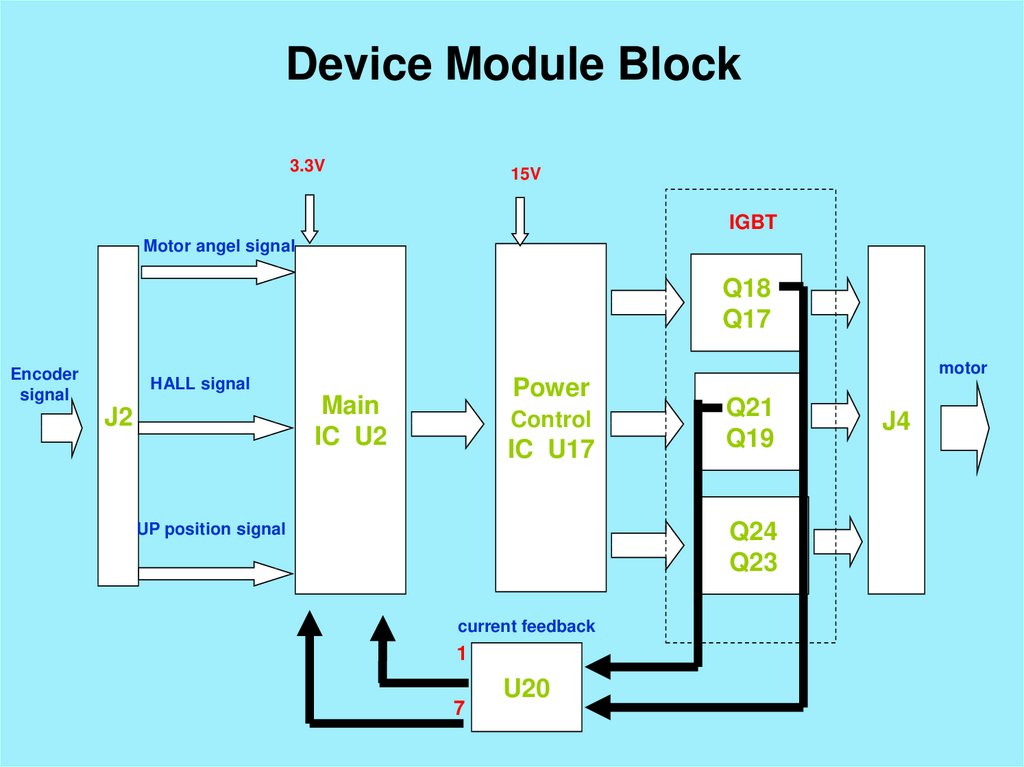
Device Module Block3.3V
15V
IGBT
Motor angel signal
Q18
Q17
Encoder
signal
motor
HALL signal
Power
Main
IC U2
J2
Control
IC U17
Q21
Q19
Q24
Q23
UP position signal
current feedback
1
7
U20
J4
12.
SOLENOID CIRCUITTrimming
U7
Q6
Wiping
U8
Q1
Back tacking
U29
Q7
Foot-lift
Master
Chip U2
U3
Q8
U4
U27
J7
Thread Tension
U23
Q5
Manual back tacking
U23
Buffer circuit
13.
POWER BOARDSolenoid control
HMI 5V
footlift
Thread Back
Trimm
wiping
tension tacking
ing
DC power supply
15V
5V
14.
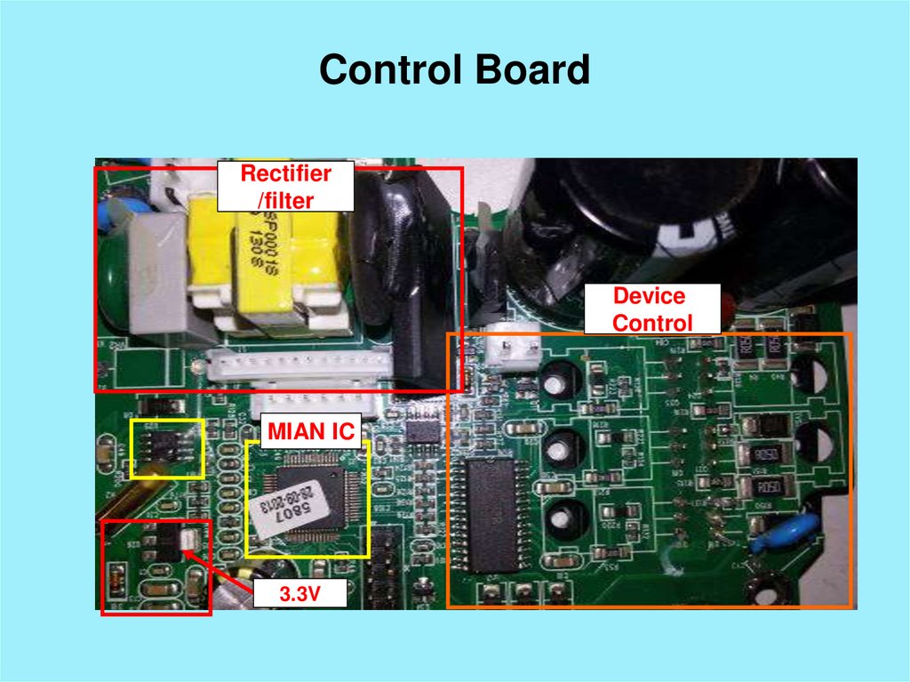
Control BoardRectifier
/filter
Device
Control
MIAN IC
3.3V
15.
Power BoardControl Board
16.
Err-01Replace
bad part
Use
diode
range
measure C8、C9 short
or not
Power on, measure
power board U10
have 15V if not or
too low or too high,
replace U10
Replace
bad part
Test
Test
Use diode range measure
control
board
Q17/Q18/Q19/Q21/Q23/
Q24 damaged or not
Replace
bad part
Use diode range and
resistor measure TVS3
R151
RTV2
R150
damaged or not
Replace
bad part
Replace u17
Replace
bad part
Test
Test
Test
PASS
17.
Power boardControl board
IGBT
C9
U10
C8
2136
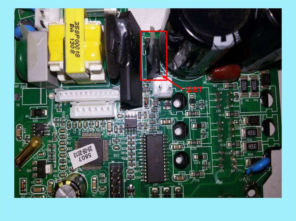
18.
Control board19.
Control board20.
Err-07Visual check
component
damaged?
Power on, use DC volt.measure control board
U20 pin4&8 have 3.3v pin1&4 pin4&7 have
1.65v if not, replace U20
Replace
bad part
Replac
e bad
part
Test
Test
PASS
21.
227222.
Control board23.
Err-08Visual check
component
damaged?
Replace
bad part
Test
Use DC Volt range
measure power board U10
have 15v if not check
u101 damaged or not
Replace
bad part
Test
Use diode range
measure
control
board
Q17/Q18/Q19/Q21,
Q23Q24 damaged?
Replace
bad part
Use diode range measure
control
board
D21/D22/D23/
R21/1R212/R213 damaged
or not
Replace
bad part
Test
Test
PASS
24.
Power boardControl board
IGBT
2136
U10
25.
Control board26.
Control board27.
Err-09Visual check
component
damaged?
Replace
bad part
Test
Use
diode
range
measure
Q7/D4/
Q9/Q8/Q11/D3/Z3/Z4
damaged or not
Replace
bad part
Test
Use resistor range
measure
R9/R10/R14/R16/R
18/R19 damaged or
not
Replace
bad part
Test
PASS
28.
IGBT29.
Power Supply30.
Err-10Visual check
component
damaged?
Use DC range measure
power biard U27 pin1&3
have 5v output or not if
not replace U27
Replace
bad part
Replac
e bad
part
Test
Test
Use diode range measure U26
/D18 on control board
damaged or not
Replace
bad part
Test
Replace U2/U6 on power
board
Replace
bad part
Test
Replace panel cable
Replace
bad part
Test
PASS
31.
CONTROL BOARDPOWER BOARD
U2
U26
U2
U6
U27
U27
D18
32.
POWER BOARD33.
CONTROL BOARD34.
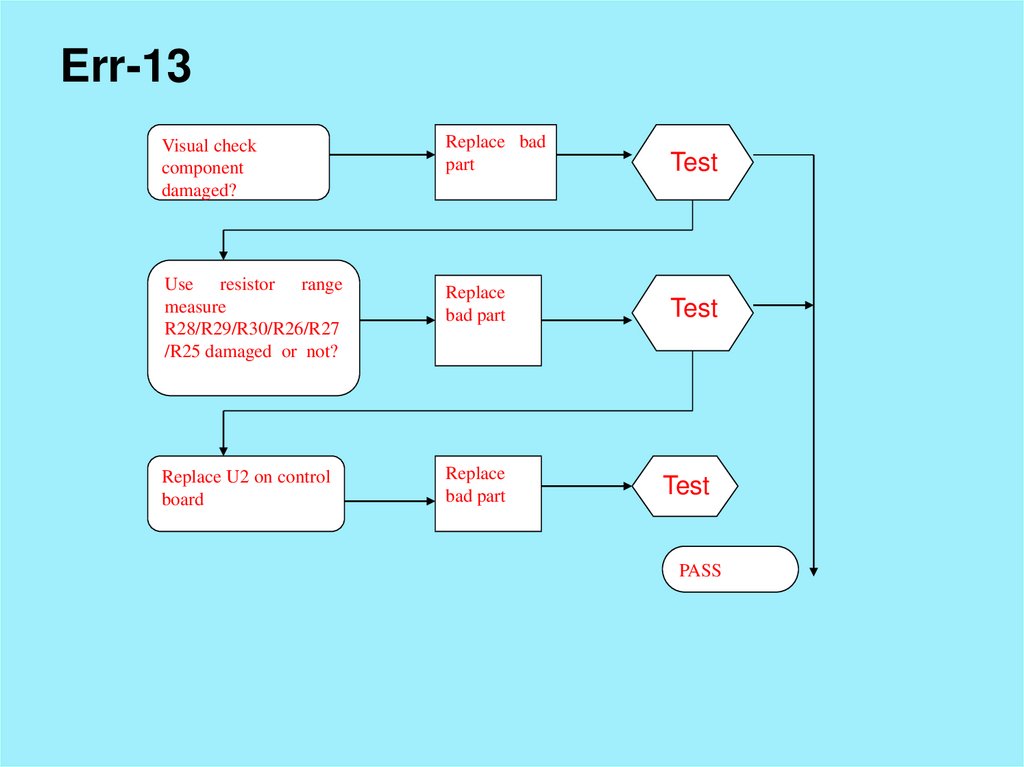
Err-13Visual check
component
damaged?
Replace bad
part
Test
Use resistor range
measure
R28/R29/R30/R26/R27
/R25 damaged or not?
Replace
bad part
Test
Replace U2 on control
board
Replace
bad part
Test
PASS
35.
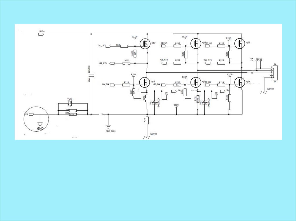
CONTROL BOARD36.
CONTROL BOARD37.
AHE5938.
Err-01Visual
check
component damaged?
Y
Replace
bad part
N
Te
st
Y
N
Power on, measure
power board U10 have
15V if not or too low
or too high, replace
U10
Y
Replace
bad part
Te
st
Y
N
N
Use diode range
measure control
board
Q17/Q18/Q19/Q21/
Q23/Q24 damaged
or not
Y
Replace
bad part
Y
Te
st
N
N
Use diode range and
resistor
measure
TVS3 R151 RTV2
R150 damaged or not
N
Replace u17
Y
Replace
bad part
Te
st
Y
N
Y
Te
st
PASS
39.
PositiveReverse side
U10
IGBT
2136
R150 R151 TVS2 TVS3
40.
41.
42.
Err-08Visual
check
component damaged?
Y
Replace
bad part
N
Te
st
Y
N
Power on, measure
power board U10 have
15V if not or too low
or too high, replace
U10
Y
Replace
bad part
Te
st
Y
N
N
Use diode range
measure control
board
Q17/Q18/Q19/Q21/
Q23/Q24 damaged
or not
Y
Replace
bad part
Y
Te
st
N
N
Use diode range and
resistor
measure
TVS3 R151 RTV2
R150 damaged or not
N
Replace u17
Y
Replace
bad part
Te
st
Y
N
Y
Te
st
PASS
43.
PositiveReverse side
U10
IGBT
2136
R150 R151 TVS2 TVS3
44.
45.
46.
Err-10Visual
check
component damaged?
Y
Replace
bad part
N
Te
st
Y
N
Use DC range measure
power biard U24
pin1&3 have 5v output
or not if not replace
U24
Y
Replace
bad part
Y
Replace
bad part
Te
st
Y
N
Use diode range
measure D16 on
control
board
damaged or not
Y
N
N
Measure R82 R57/
resistance value is
correct
Te
st
Y
Replace
bad part
Te
st
Y
N
Replace U3 U11
Y
Te
st
PASS
47.
Reverse side1
U24
D16
Positive