


 Board")


 electronics
Similar presentations:


")
Understanding how System Shut Down operates
1.
Viera PlasmaDisplay PC Board Recycling Component Level Repair
Course 3
Understanding how System Shut Down operates
2.
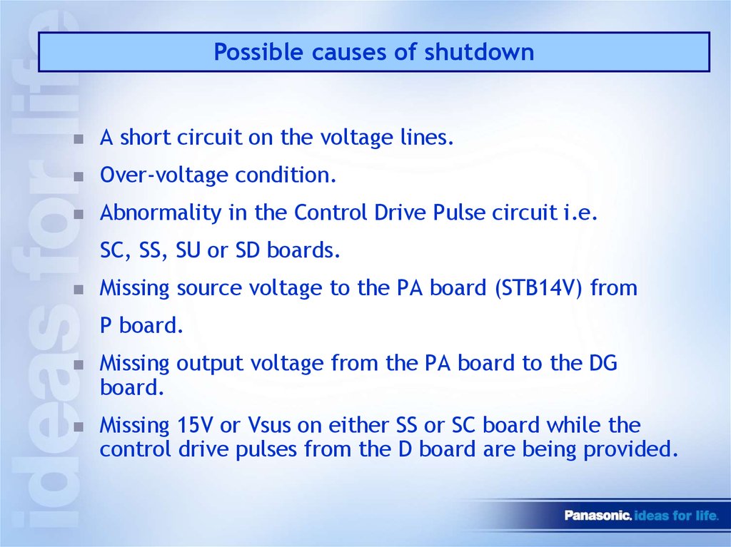
Possible causes of shutdownA short circuit on the voltage lines.
Over-voltage condition.
Abnormality in the Control Drive Pulse circuit i.e.
SC, SS, SU or SD boards.
Missing source voltage to the PA board (STB14V) from
P board.
Missing output voltage from the PA board to the DG
board.
Missing 15V or Vsus on either SS or SC board while the
control drive pulses from the D board are being provided.
3.
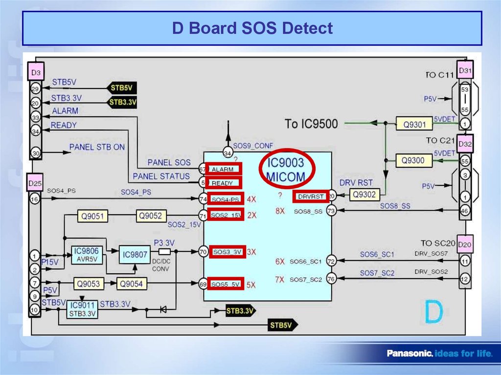
D BOARD SOS DETECTD Board SOS detect
SOS line
SOS 2
SOS 3
Line Monitored # of times LED
blinks
15V
2 blinks
3 blinks
SOS 4
P3.3V(15V &
STB5V)
PS
SOS 5
5V
5 blinks
SOS 6
SC1
6 blinks
DRV RST
5V DET
6 blinks
SOS 7
SC2
7 blinks
SOS 8
SS
8 blinks
4 blinks
4.
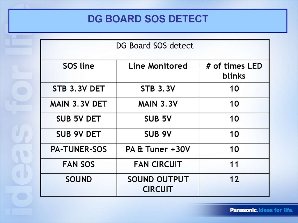
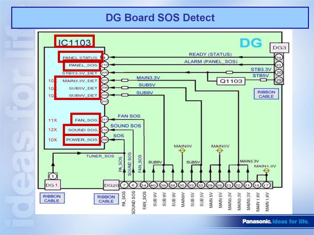
DG BOARD SOS DETECTDG Board SOS detect
SOS line
Line Monitored
# of times LED
blinks
STB 3.3V DET
STB 3.3V
10
MAIN 3.3V DET
MAIN 3.3V
10
SUB 5V DET
SUB 5V
10
SUB 9V DET
SUB 9V
10
PA-TUNER-SOS
PA & Tuner +30V
10
FAN SOS
FAN CIRCUIT
11
SOUND
SOUND OUTPUT
CIRCUIT
12
5.
PA Board Test Points6.
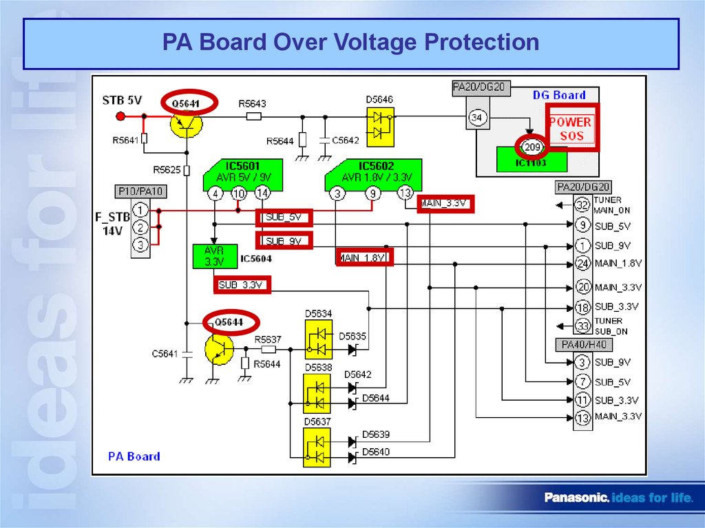
PA Board Over Voltage Protection7.
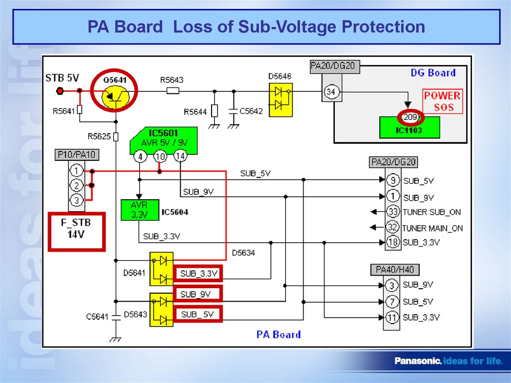
PA Board Loss of Sub-Voltage Protection8.
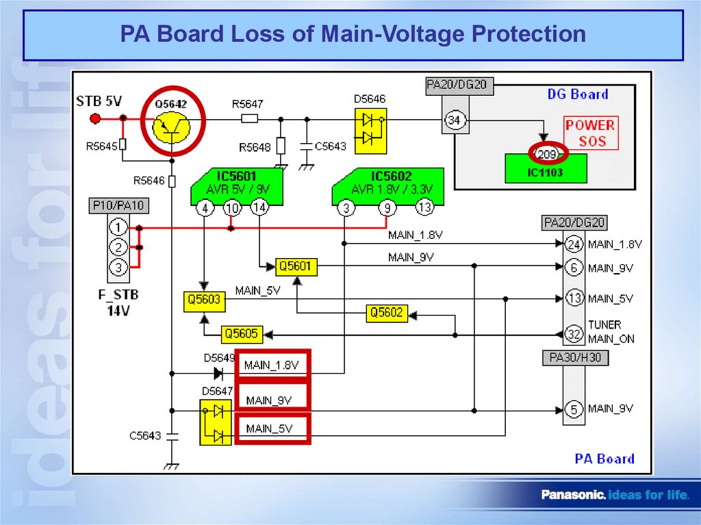
PA Board Loss of Main-Voltage Protection9.
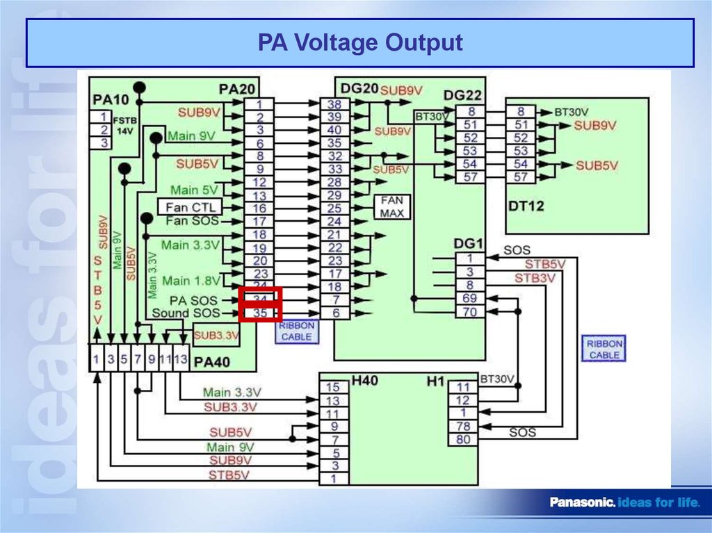
PA Voltage Output10.
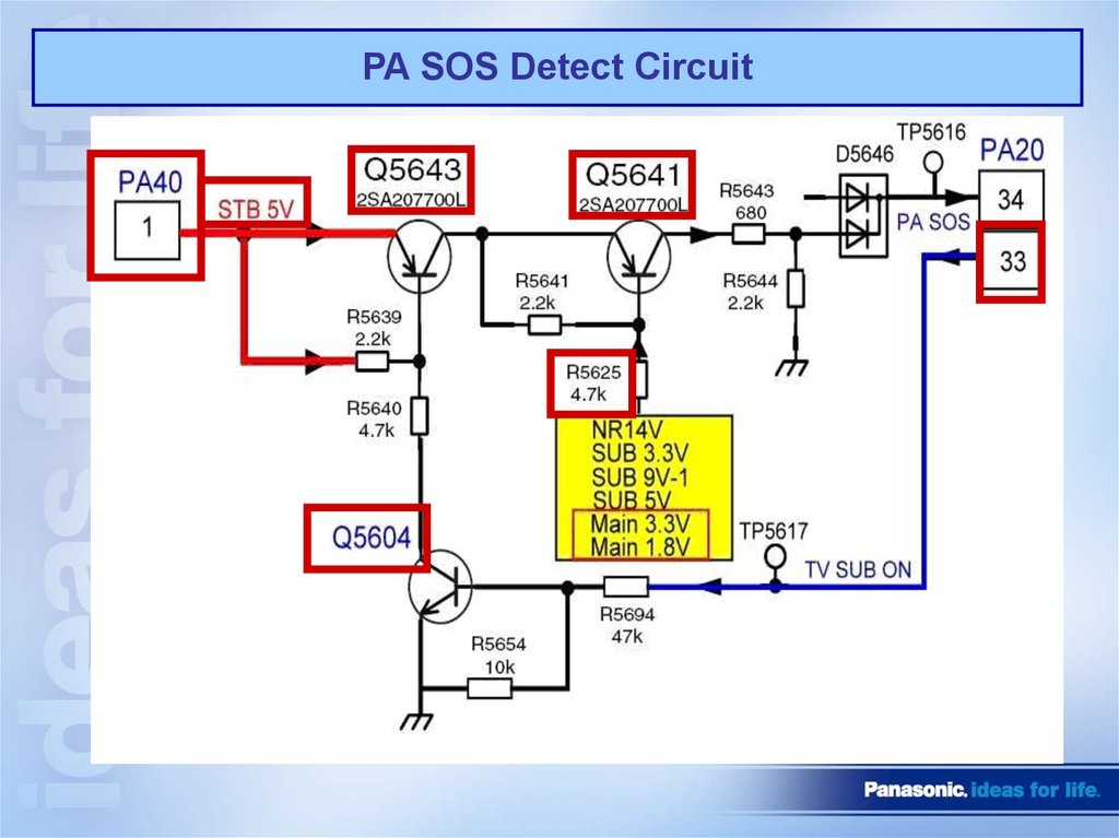
PA SOS Detect Circuit11.
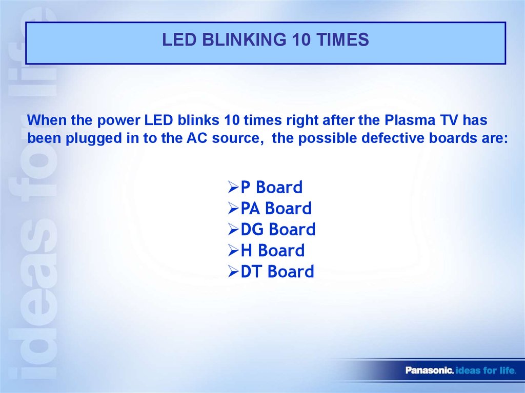
LED BLINKING 10 TIMESWhen the power LED blinks 10 times right after the Plasma TV has
been plugged in to the AC source, the possible defective boards are:
P Board
PA Board
DG Board
H Board
DT Board
12. How to Rule out the P Board
1.Use a Peak Hold Meter for voltage reading
NOTE: Follow this procedure when the click sound of the relay can be heard
after the unit is plugged in. If the relay does not click, check the STB 5V
from the P board. If the STB 5V is missing, the P board may be defective.
(If STB 5V is OK, the DG board may be defective.
2.
3.
Disconnect Connector P10 on the P board. (Make sure that the TV is
unplugged)
Because you only have 2 – 3 seconds to measure the STB14V, place your
meter’s probe at pin 1 of connector 10 of the P board before plugging the
TV in to the AC line.
4.
Plug the TV in to the AC line while still holding the probe at Pin 1.
5.
Check to see if the 14V comes up. If it does not come up the P board is
defective. If it does, (since it may take some involvement to determine
which of the PA or DG board is defective) it is OK to order both the PA and
DG board together.
13. To rule out H Board
1.Disconnect connector H40 then plug Plasma TV to AC
line.
2.
If the power LED stops blinking, the H board may be
defective, otherwise another board is causing the
problem.
NOTE: It is recommended that the PA board be replaced
at the same time if the H board is suspected to be
defective and will be replaced.
14. To rule out the DT (Digital Tuner) Board
1.Remove the DT board and then plug the Plasma TV into an
AC source.
Note: When the DT board is removed, the unit will still power
up but all functions are disabled due to the lack of data
communication
2.
If the power LED stops blinking the DT may be defective
otherwise, another board is causing the problem.
3.
Other possible causes of blinking are the PA or DG board.
15.
D Board SOS Detect16.
DG Board SOS Detect17.
DG Board SOS Detect18.
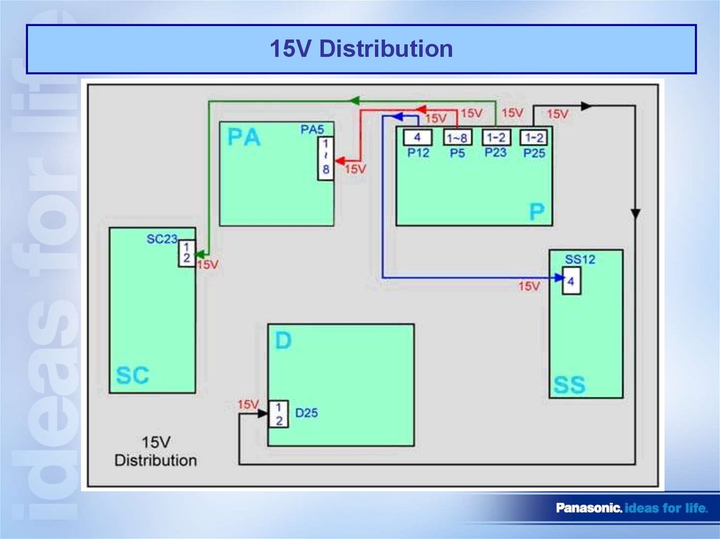
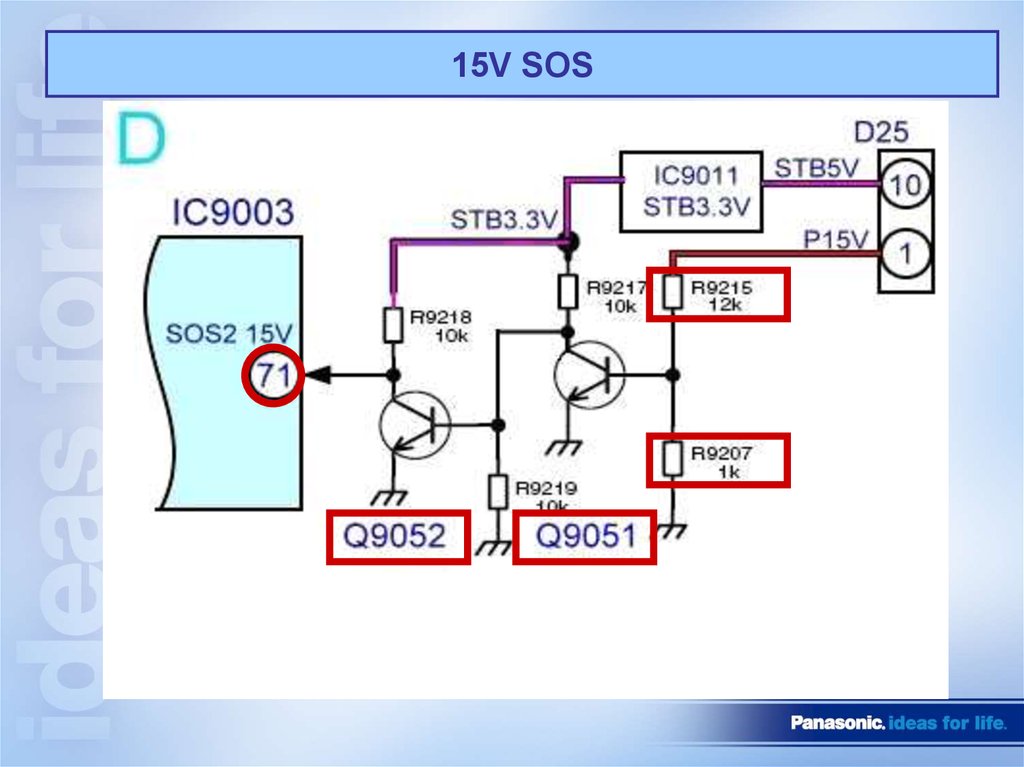
15V Distribution19.
15V SOS20.
LED BLINKING 5 TIMES• This blinking code is caused by an
abnormalities in the 5V voltage supply line.
• Other possible cause is a problem in Vda
supply voltage line.
21.
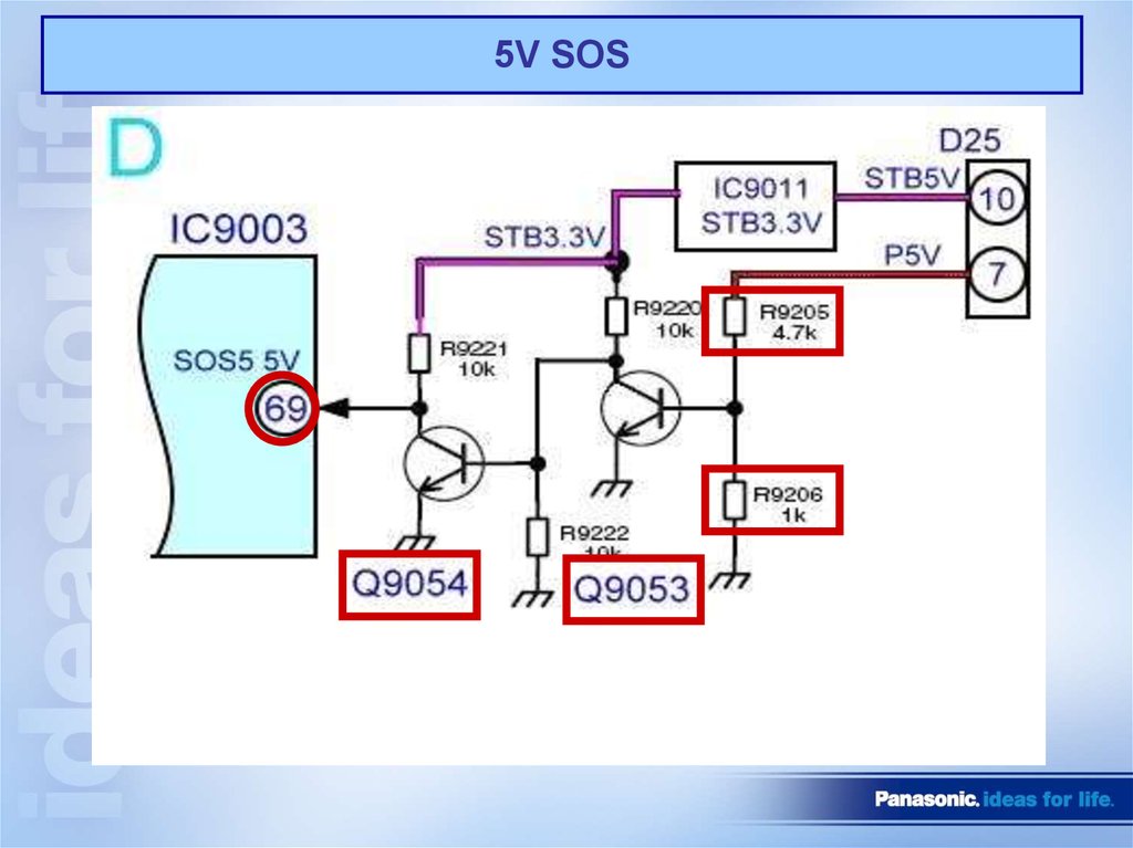
5V Distribution Line22.
5V SOS23.
Other Cause of 5V SOS• The Power LED can also blink 5 times if the
Vda voltage is shorted. This is normally
caused by the Panel demultiplexer ICs.
24.
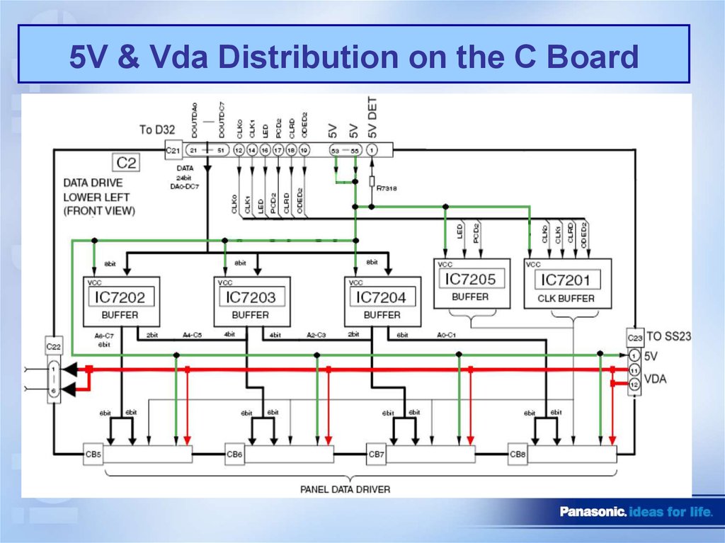
5V & Vda Distribution on the C Board25.
Procedure to properly isolate C Board• When the ribbon cables from the D board to the C
boards are disconnected in order to isolate the C boards,
the LED will blink 6 times.
• To properly isolate the C boards to avoid 6 blinks,
TP9387 (on the D board) should be grounded by a
1Kohm resistor.
Note: The next slide will show reasons why SOS 6
blinks is generated when the ribbon cables are removed.
• The Vda connector should also be disconnected.
26.
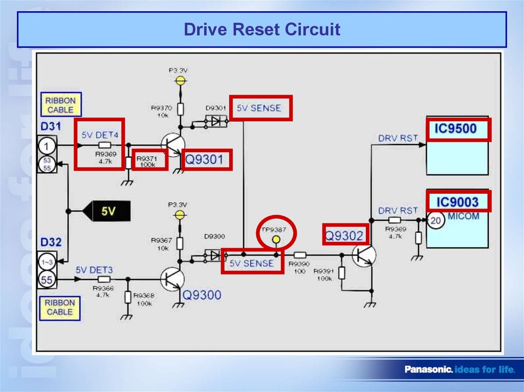
Drive Reset Circuit27.
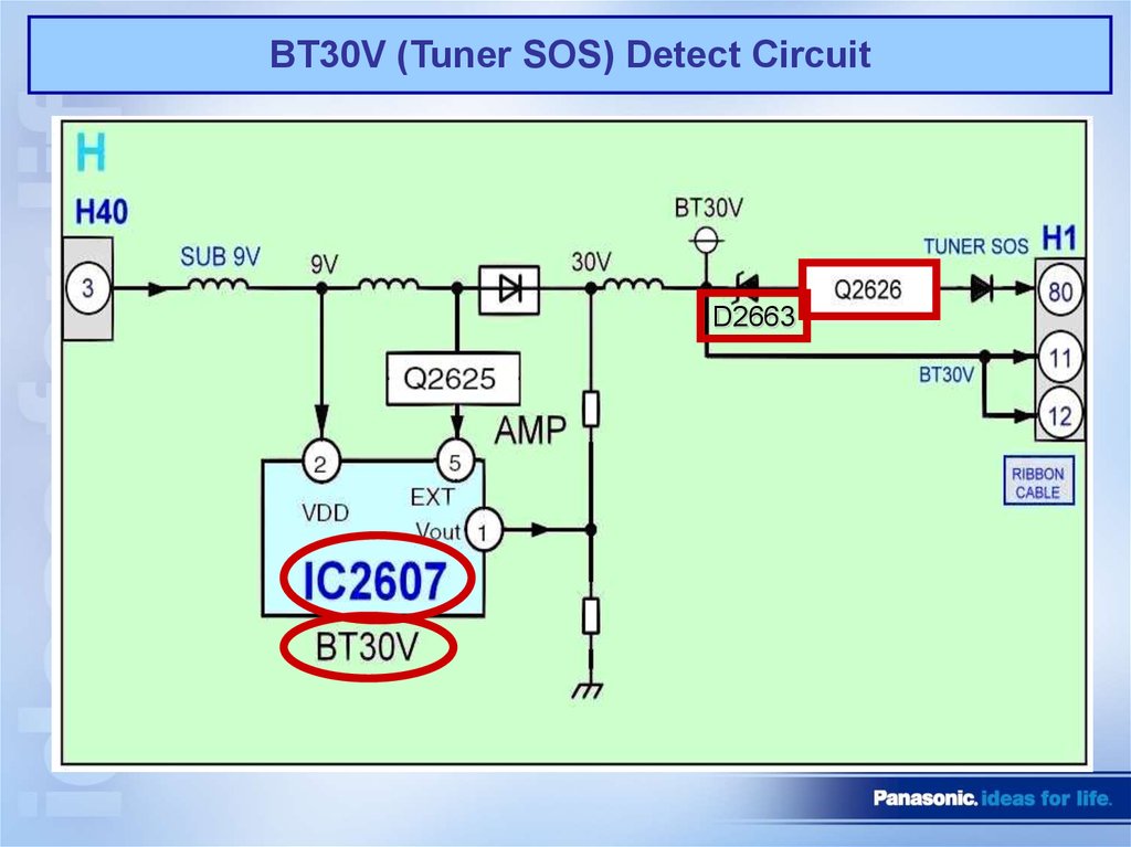
BT30V (Tuner SOS) Detect CircuitD2663
28.
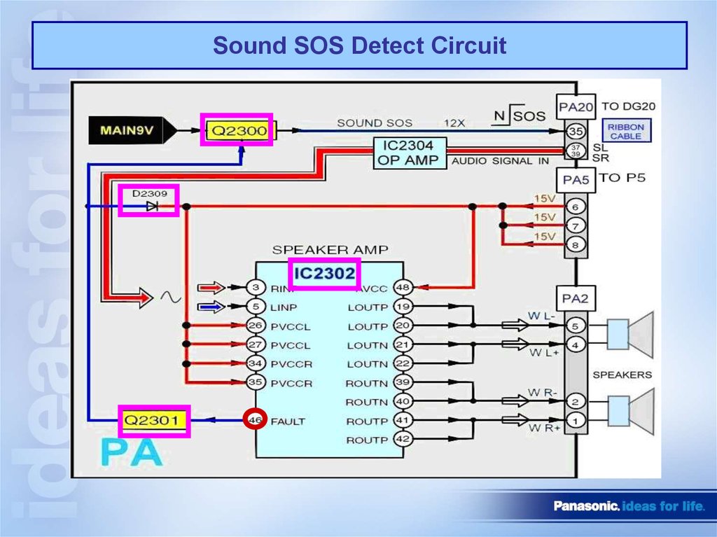
Sound SOS Detect Circuit29.
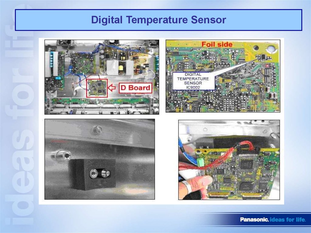
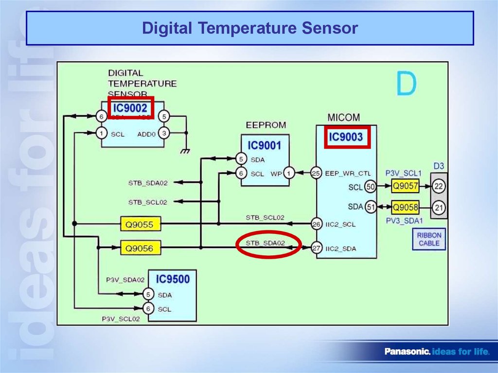
Digital Temperature Sensor30.
Digital Temperature Sensor31.
Digital Temperature Sensor (continued)32.
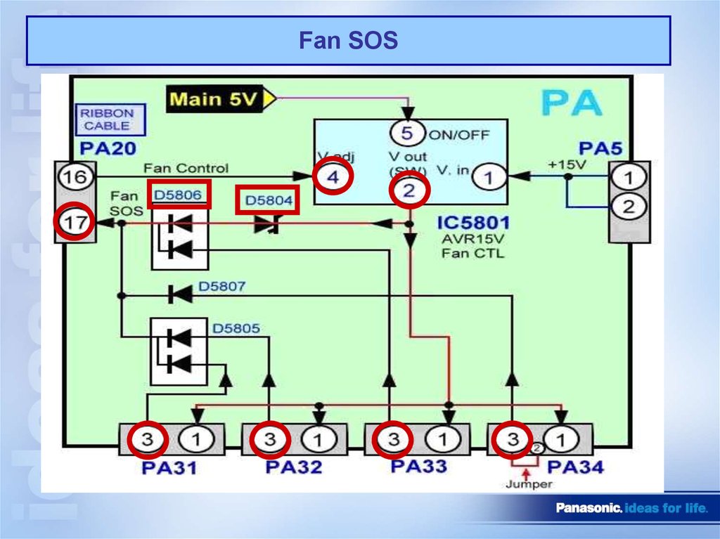
Fan SOS33.
Fan SOS• To determine if the fan is the cause of the 11 blinks,
simply use a peak hold meter to determine if pin 3 of the
fan connector goes high before shutdown.
• If it does, the fan is defective.
• If not, check the other fans and the fan drive circuitry.
34.
No Video and No OSDDetermining whether a no video or no OSD symptom is caused by the
video process or the panel drive circuit
35.
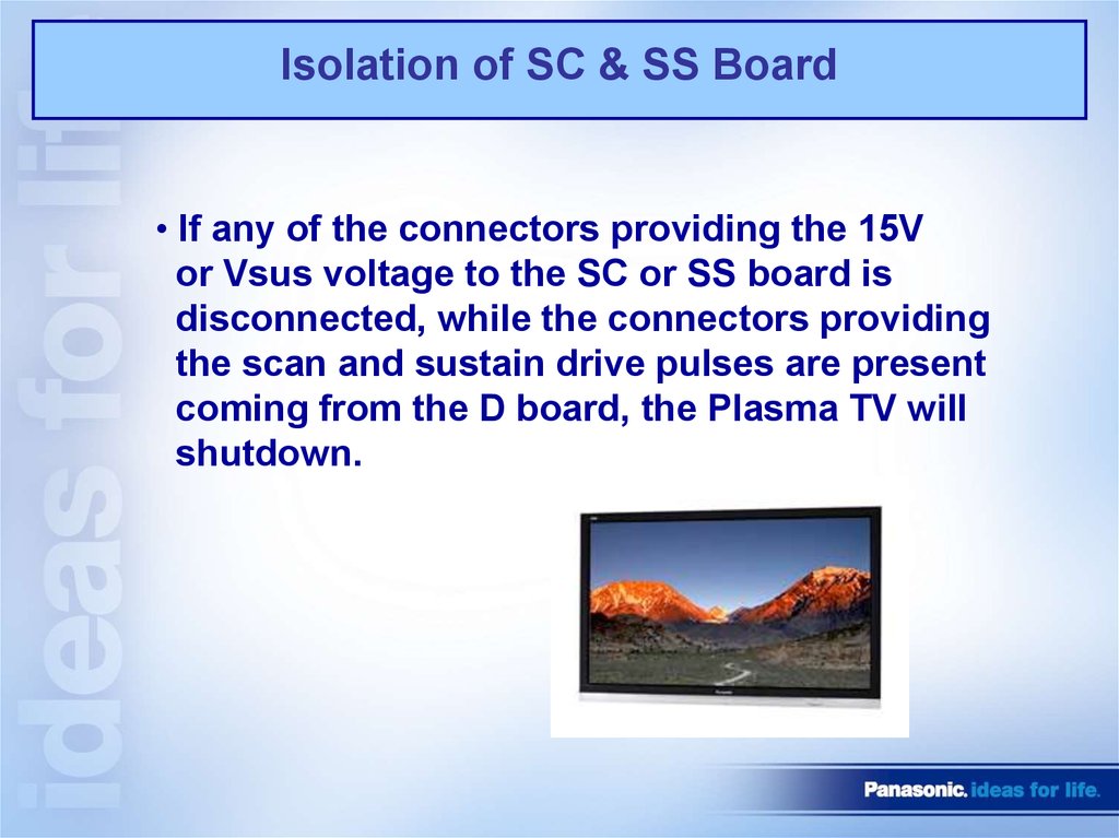
Isolation of SC & SS Board• If any of the connectors providing the 15V
or Vsus voltage to the SC or SS board is
disconnected, while the connectors providing
the scan and sustain drive pulses are present
coming from the D board, the Plasma TV will
shutdown.
36.
Isolation of the SC & SS Board37.
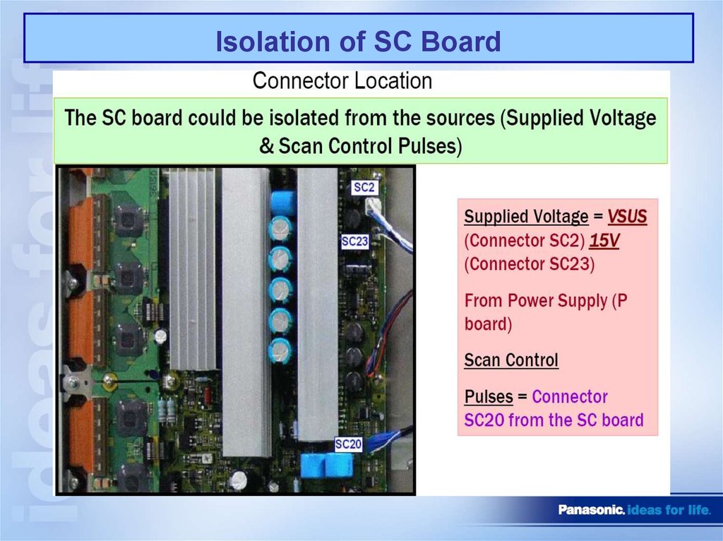
Isolation of SC Board38.
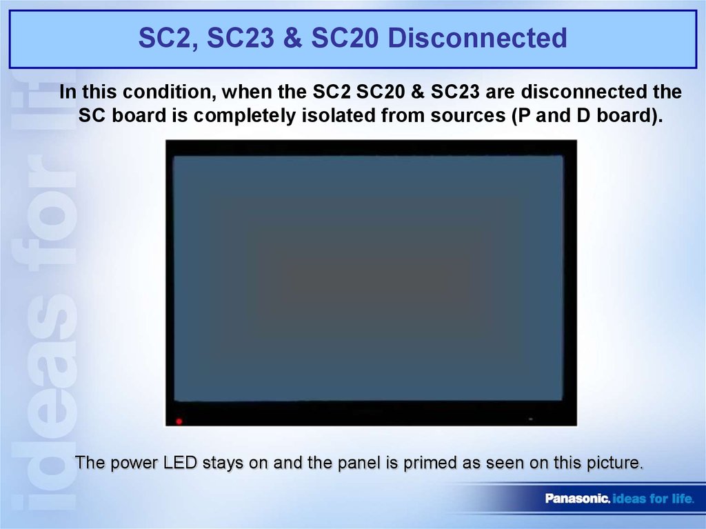
SC2, SC23 & SC20 DisconnectedIn this condition, when the SC2 SC20 & SC23 are disconnected the
SC board is completely isolated from sources (P and D board).
The power LED stays on and the panel is primed as seen on this picture.
39.
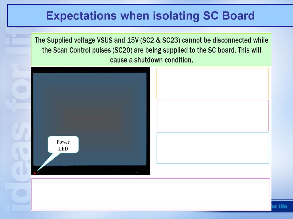
Expectations when isolating SC Board7
40.
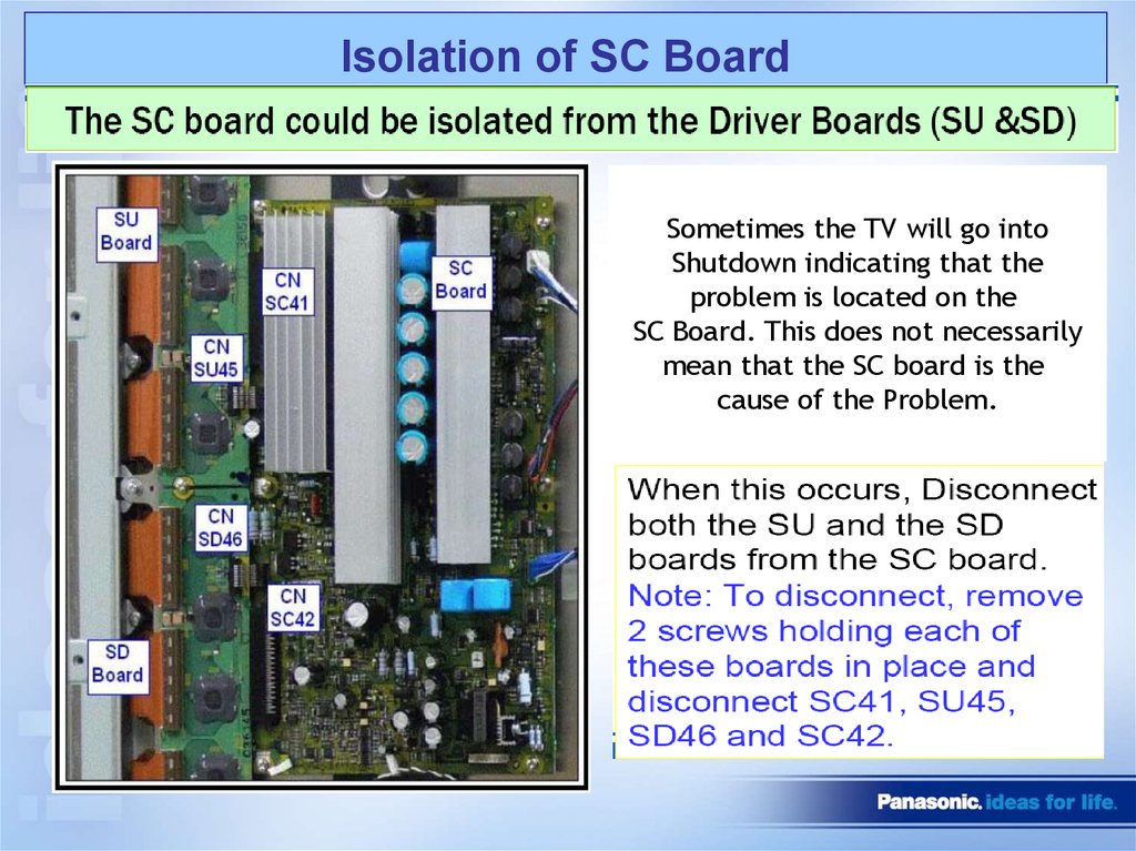
Isolation of SC BoardSometimes the TV will go into
Shutdown indicating that the
problem is located on the
SC Board. This does not necessarily
mean that the SC board is the
cause of the Problem.
41.
Isolation of SC Board42.
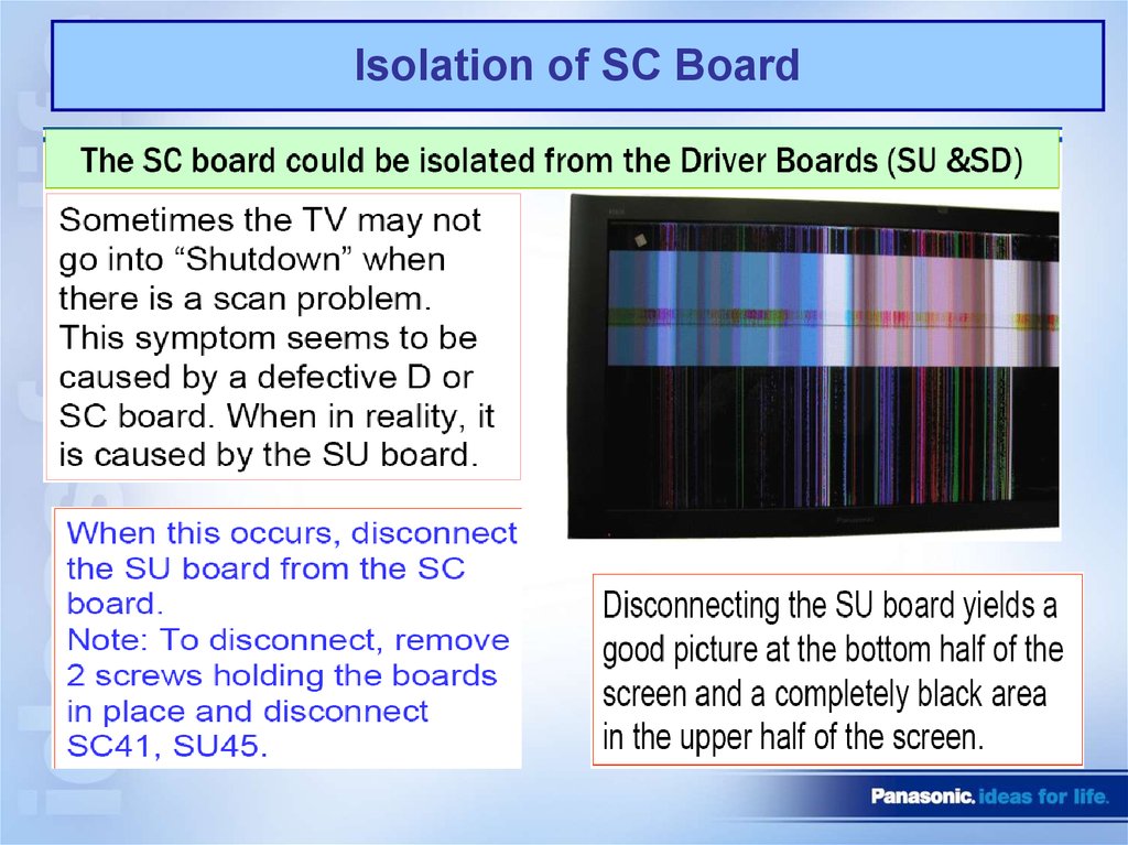
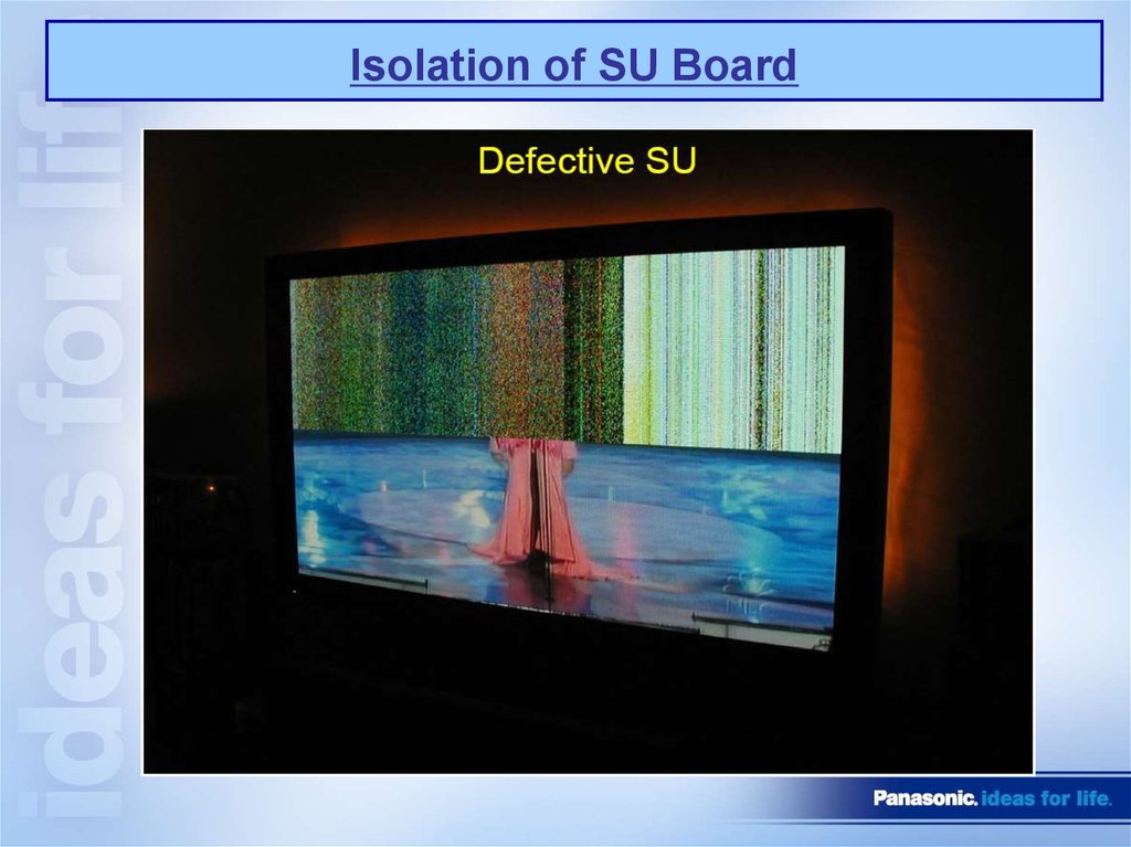
Isolation of SU Board43.
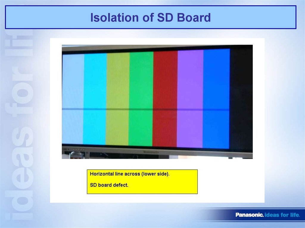
Isolation of SD Board44.
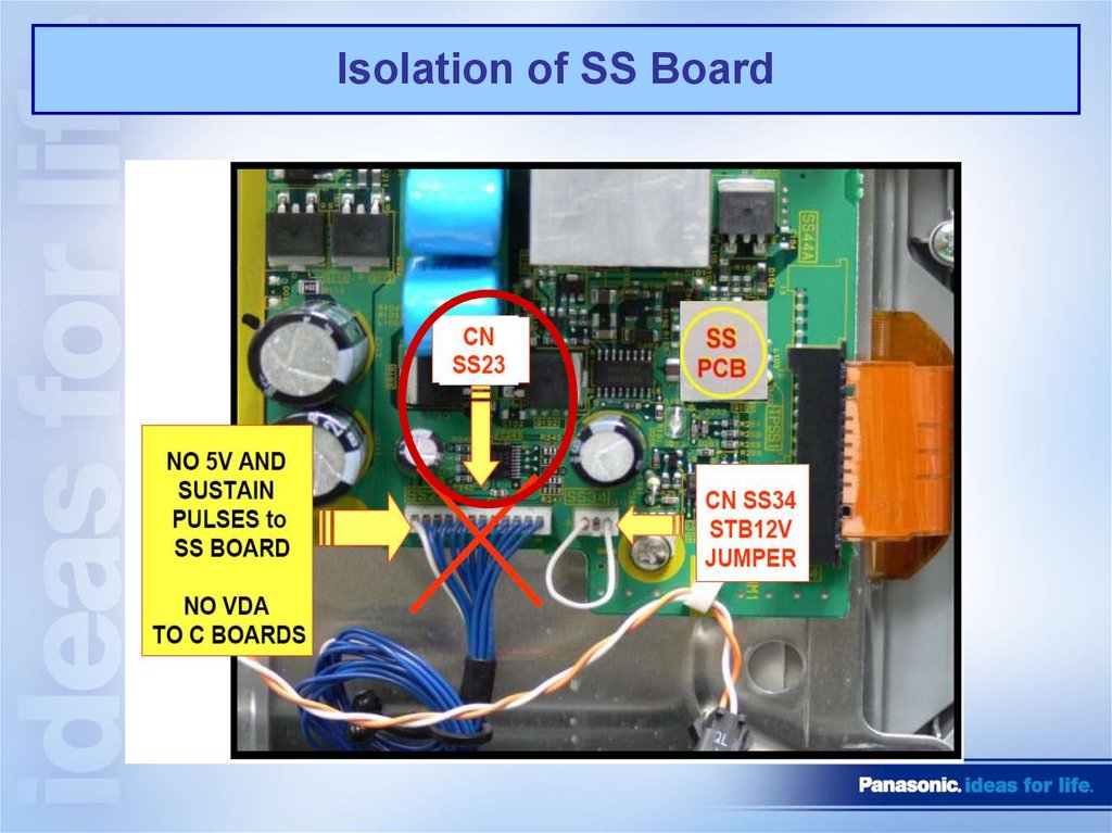
Isolation of SS Board45.
Isolation of SS Board46.
Isolation of SS Board47.
Isolation of SS BoardSS23 Disconnected on the SS board
(No Drive pulses from the D board)
No VDA voltage to the C boards
(Reason why the screen is black)
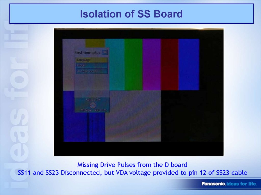
48.
Isolation of SS BoardMissing Drive Pulses from the D board
SS11 and SS23 Disconnected, but VDA voltage provided to pin 12 of SS23 cable
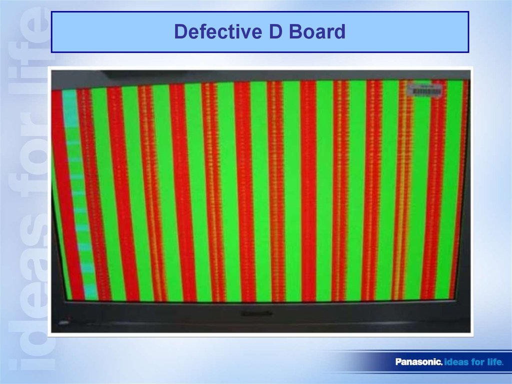
49.
Defective D Board50.
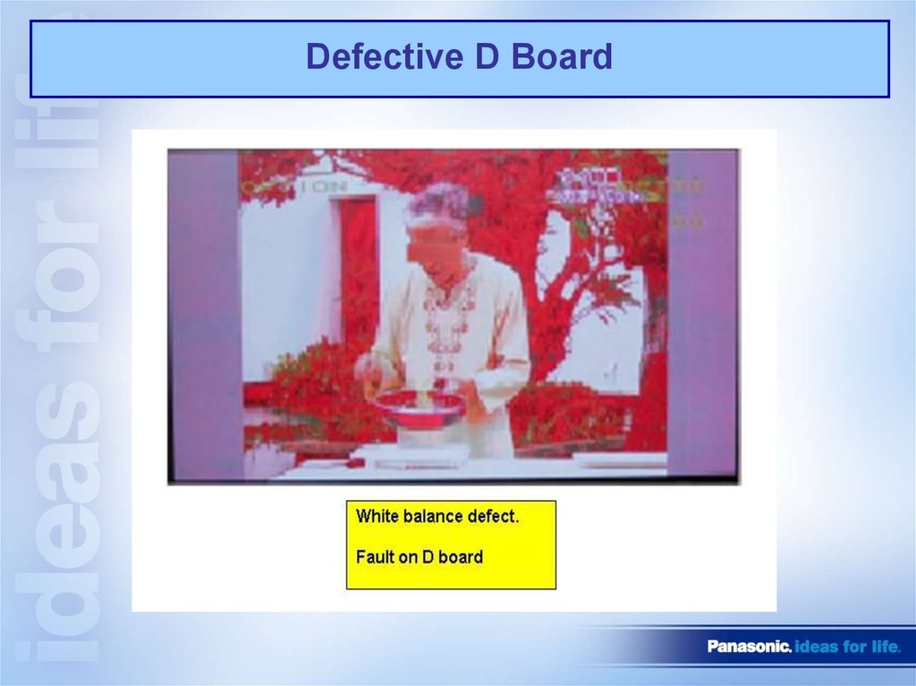
Defective D Board51.
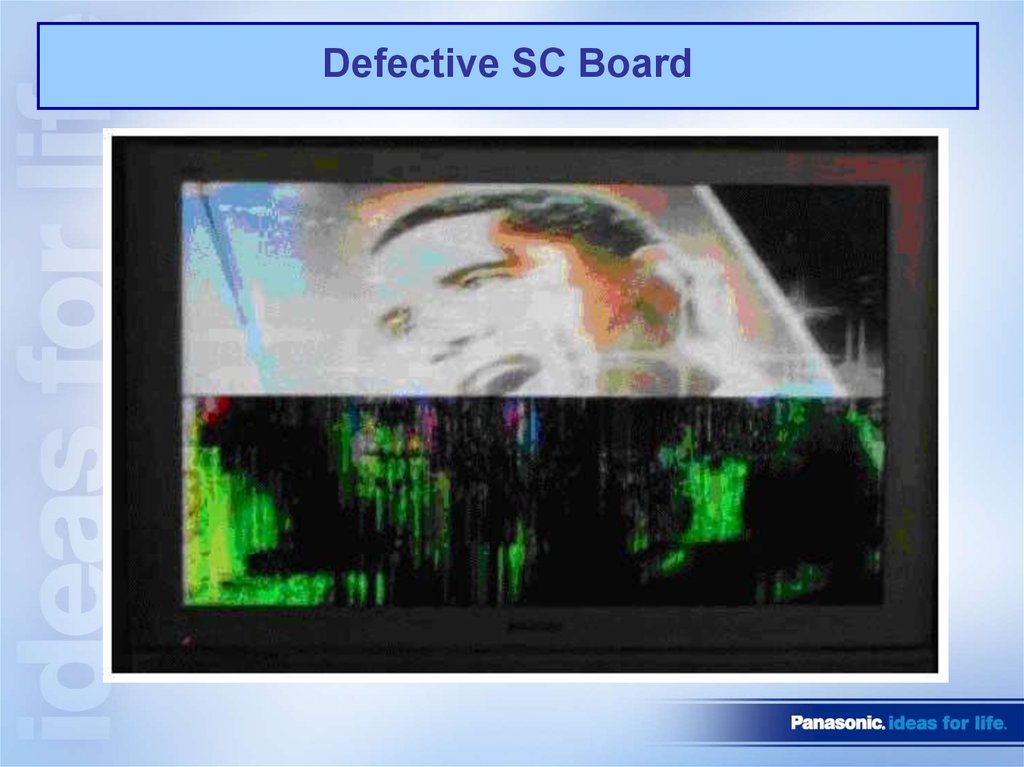
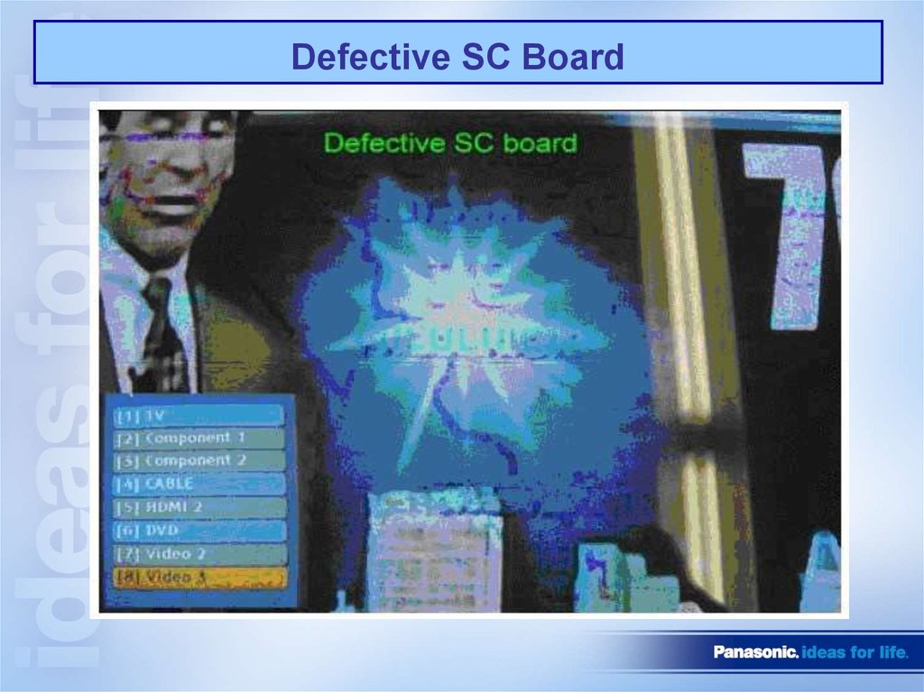
Defective SC Board52.
Defective SC Board53.
Thank YouFor Completing Course Three
Course Four
Troubleshooting Hints /
Common Symptoms