


")
")
")
")
")
")
")


 software
Similar presentations:


Premilled guide
1.
PREMILLED GUIDE2. Pre-Milled Workflow
• New Job (Fixture is automatically Imported)• Fixture must have the CYLINDER_POSITION curve.
• Import .STL File for Milling
• Import Blank File
• Blank must have the following curves:
• CYLINDER_ORIGIN
• PRE_MILLED_POSITION
• PRE_MILLED_PHASE (Optional – For Tri-Lobes only)
• Select Strategy for Milling
• Calculate Machining
3. Pre-Milled Setup Pre-Requisites
• Fixture FileMust be properly orientated with the machine’s axes.
• Blank Files
One for each blank size
• Information for orientation / positionining
Blank – Fixture relationship
Drawings with measurements Help
• Generated .STL Files with Interface Geometry
3Shape
ExoCAD
Dentalwings
4. Creating your Equipment & Blanks
Creating your Equipment & Blanks• It is usually ideal to prepare your Equipment
and Pre-Milled Blank files in an external CAD
Software and later import it into SUM3D with
all of the appropriate information.
• Some examples of this software could be:
Solidworks – Must be exported in IGES format to
maintain curves and layers.
Rhinoceros – Must be exported in Rhino 4 Format.
5.
Discussion PointsEquipment Creation (.EQP Files)
Pre-Milled Blank Creation (.BLK Files)
6.
EQUIPMENT (.EQP)7.
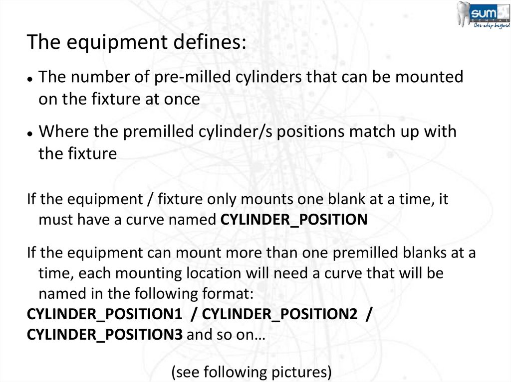
The equipment defines:The number of pre-milled cylinders that can be mounted
on the fixture at once
Where the premilled cylinder/s positions match up with
the fixture
If the equipment / fixture only mounts one blank at a time, it
must have a curve named CYLINDER_POSITION
If the equipment can mount more than one premilled blanks at a
time, each mounting location will need a curve that will be
named in the following format:
CYLINDER_POSITION1 / CYLINDER_POSITION2 /
CYLINDER_POSITION3 and so on…
(see following pictures)
8.
9.
10.
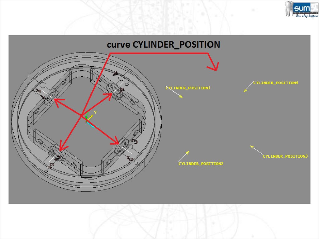
IMPORTANTThe Fixture must be orientated to match the X, Y & Z axes exactly as they are
laid out in the actual Milling Machine.
The end of the CYLINDER_POSITION curve must be placed in the center of
the Z axis and exactly where you want the blank’s curve to match up to:
A curve in the blank will automatically align to this exact point when it is
imported.
The CYLINDER_POSITION curve must be reside in
the -DM-Clamps layer. (The name of the layer is case-sensitive)
11.
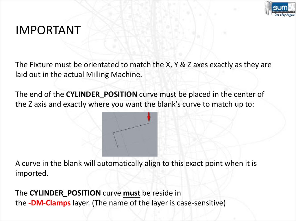
IMPORTANTWhen a new CAM File is created, the equipment should automatically load (thanks to
the postprocessor’s customization code: LOADEQP. The blank will automatically align
to the tip of the CYLINDER_POSITION curve.
Pay close attention to the curve direction!
The curve direction should be pointing outward toward the blank. If this direction is
incorrect, the imported blank will be placed on the opposite side of the curve, which
could be inside of your fixture rather than outside.
The length of the curve is not important. It is the ending point that we are concerned
about for placement.
12.
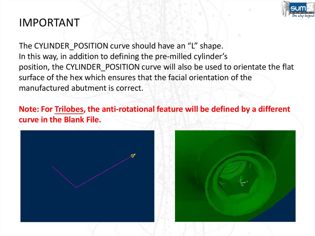
IMPORTANTThe CYLINDER_POSITION curve should have an “L” shape.
In this way, in addition to defining the pre-milled cylinder’s
position, the CYLINDER_POSITION curve will also be used to orientate the flat
surface of the hex which ensures that the facial orientation of the
manufactured abutment is correct.
Note: For Trilobes, the anti-rotational feature will be defined by a different
curve in the Blank File.
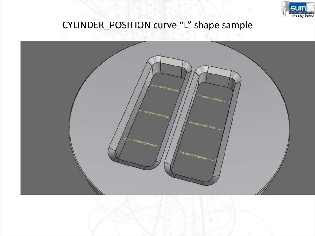
13.
CYLINDER_POSITION curve “L” shape sample14. Converting your prepared file into an Equipment File (.EQP)
• Before SUM3D can use your preparedequipment file, it needs to be imported.
• Follow the steps on the following slides to
prepare the file in SUM3D for regular use.
15. Converting your prepared file into an Equipment File (.EQP)
1.Open SUM3D (Maximum Level UI)
2.
Go to File > New on the File Menu
Navigate to the C:\sum\DENTAL\SUP\<MACHINE NAME\ directory and give your
fixture a name and change the Save as type to: “All Files”. Don’t forget to include the
.eqp as the file extension after the name as shown below:
16. Converting your prepared file into an Equipment File (.EQP)
You should now see a blank CAM file.3.
Click on File > Import on the File Menu
Change the Files of Type drop-down to match the format that you exported.
Navigate to the location of your Equipment File that you exported from you CAD
Software and select it from the list
Ensure that your options to the right are all set to Yes and that the Trimming Curves is
set to 2D.
17. Converting your prepared file into an Equipment File (.EQP)
• Check the Layer Configuration to ensure that youhave everything assigned to the correct layer (For
the equipment this should be in the -DM-Clamps
Layer):
18. Converting your prepared file into an Equipment File (.EQP)
• Click on Curve > Change Name to check the Namesof the Curves to verify that these are correct:
NOTES:
Remember that if you have only one holder, it will
be named CYLINDER_POSITION
The example screenshot to the right illustrates a
fixture that can hold 3 Pre-Milled Blanks at a
time.
19. Converting your prepared file into an Equipment File (.EQP)
• Click on Curve > Reverse Curve to check the Namesof the Curves to verify that these are correct:
OK
NOT OK
20. Converting your prepared file into an Equipment File (.EQP)
• If the Curves and the Layers are correct, youshould be able to simply close out of the
SUM3D Software and continue with the
Pre-Milled Blank creation.
21.
Pre-Milled Blanks(.BLK)22.
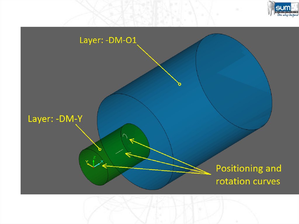
Pre-Milled Blank Files (.BLK)The .BLK file must meet the following requirements:
The Pre-Milled Blank Surface and Curves must reside within the DM-O1 Layer.
NOTE: It is -DM-O1 not -DM-01 (Letter O, not Number 0)
If there are protection surfaces, these must be created and reside
in the -DM-Y Layer.
The Following Curves must be present:
CYLINDER_ORIGIN
PRE_MILLED_POSITION
PRE_MILLED_PHASE (Only for Tri-Lobes)
23. CYLINDER_ORIGIN Curve
The CYLINDER_ORIGIN curve’s purpose is to match up with
the CYLINDER_POSITION Curve on the equipment.
• The direction of this curve should be in opposition to the
CYLINDER_POSITION Curve on the equipment.
• This curve must reside in the -DM-O1 Layer.
24. PRE_MILLED_POSITION Curve
• The PRE_MILLED_POSITION curve’s purpose is to place .STLfile in correct position within the blank. This curve must also
reside in the -DM-O1 Layer.
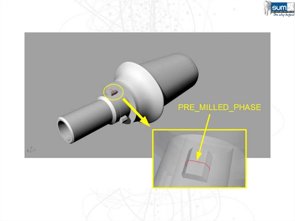
25. PRE_MILLED_PHASE Curve
• This curve is used to match up the rotation orientation of thetri-lobes (or similar shapes) on an abutment. This curve must
also reside in the -DM-O1 Layer
26.
27.
28.
29.
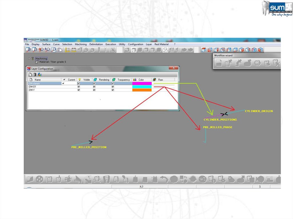
30.
CYLINDER_ORIGIN and PRE_MILLED_POSITIONFor both these curves, the “hook” is corresponding to their ends.
The CYLINDER_ORIGIN curve is used to place the object at the
end of the CYLINDER_POSITION curve, that is located on the
equipment (that must be imported into the working file before
the abutment import and before the cylinder stock import).
The PRE_MILLED_POSITION curve is used to reposition the
abutment that has been imported. The end more “external” of
the abutment hole axis (or another cylindrical part) is positioned
at the end of this curve.
31.
PRE_MILLED_PHASEPrevious picture also show an additional curve (not mandatory),
it’s the PRE_MILLED_PHASE curve.
It allows to orient the “timing” of the imported abutment in
order to correspond to the “cylinder” timing.
If this curve is not there, the “timing” executed during the
abutment import remains applied, otherwise a correspondence
between the shape of curve PRE_MILLED_PHASE (whose
orientation is not important) and the shape of imported
abutment is searched.
The PRE_MILLED_PHASE curve must represents a portion of the
abutment geometry, enough to determine the unequivocal
correspondence to the shape of the imported abutment.
32.
IMPORTANTThe PRE_MILLED_PHASE curve must be positioned in same area
in which the corresponding part to be coupled (it’s into stl file to
import) will be placed, in order to be able to determine the
unambiguous correspondence with the shape of the imported
abutment.
If that curve were to be placed in a not correct point, a
"matching error" message will appears during the blank import
(cylinder premilled. "blk").
33. Enhancement 2015
In order to allow to correctly position the "pre-milled abutments"even when it is expected that the interface (connection) type in the
STL file has wrong or possibly unknown sizes, has been added the
capability to add to the name of the connection positioning curve in
the .blk (pre-milled cylinders) files, a key that allows to "click" a point
on the STL connection interface, that will be moved to the curve
position. The key to add to the "PRE_MILLED_POSITION" curve is
"_PICK".
If SUM3D detects that the positioning curve in the ".blk" file has name
"PRE_MILLED_POSITION_PICK", wait for the manual "picking" of a
point on the connection, that will be moved (with all the abutment) to
the end of the curve PRE_MILLED_POSITION_PICK.
34. Enhancement 2015
In the creation of the BLK files (cylindric blanks) for the pre-milled abutments,it's now possible to insert, in the field for the name of the
PRE_MILLED_POSITION curve, a diameter and depth for the detection of the
coupling plane, useful for the correct positioning of the abutments with
"internal" type interface
Example:
PRE_MILLED_POSITION_3.8_5.5
it means that at the end of the curve will be located the coupling plane of the
abutment, reachable in the space defined by the given "diameter" and
"depth" values: 3.8 mm e 5.5 mm
The "_" letter is used as separator among the key PRE_MILLED_POSITION,
the value for diameter and the value for depth
The detection method for searching of the coupling plane is the same already
used in the "REPLACE" operations, for the "internal" type interfaces
35. Machining Strategy
<EFTC>(Extend Fence To Cylinder)
Option for 4 axis
continuously 360 degree
(like a lathe)
If you have a 4 axis machine,
the rough process need to
be modified with EFTC so
the material will be remove
completly for the right
finishing. (see the picture)
Otherwise some material
doesn’t allow the right
finishing process.
36. Machining Strategy
<PREM2><PREM2/ang1/ang2/step/oversize><PD..>
ang1
tool axis rotation angle related to the machining angle. Normally it’s z
ang2
angular pitch along the points of spiral’s turns applied after previous
longitudinal movements
step
step (millimeters) of spiral’s coils
oversize
oversize material to left in longitudinal movements that will be remov
by spiral movements
<PD...>
Previous Diameter, diameter of previous used tool, in case of similar
machining in sequence with tools of different diameters (bigger
diameters). In this case machining will be applied only where a bigger
previous tool didn’t properly mill the surface.
37. Machining Strategy
<PREM2><PREM2/ang1/ang2/step><SO><ZI0.5>
ROUGHING 4 AXES
ZI…
Z Increment with the increment value between passes
38. Machining Strategy
<PREM3>This machining operation
allow to mill in 3 axis <PREM3>
or in 4 axis <PREM3/...>.
The fourth axis will be
inclinated in order to mill
under the equator.
Sample: <PREM3/10> the
angle will be inclinated 10
degree in order to machining
better the area near the
equator (top-bottom)
39. Machining Strategy
<SO>Spiral only
Option for the 4 axis
machining (lathe)
40. Machining Strategy
<EM>This machining operation
allow to handle the finishes of
some areas such as the
separation between modeling
and the emergency profile.
<EMx/y>
• x
starting value
• y
ending value
41. Machining Strategy
Ex. 1:<EM0/10>
42. Machining Strategy
Ex. 2:<EM10/0>
43. Machining Strategy
Ex. 3:<EM0.5/0.5>
44. Machining Strategy
Ex. 4(Engraving case):<EM0.5/10>
Enable the layer –DM-03
45. Machining Strategy
Ex. 4(Engraving case):<EM0.5/10>
46.
Contact usCIMSYSTEM s.r.l.
Via Monfalcone, 3
20092 Cinisello Balsamo (MI) Italy
Phone +39 02 87213185
Fax +39 02 6129306
Web Site:
www.sum3ddental.com
www.cimsystem.com
www.rhinoplugins.com
Technical Support : support@cimsystem.com