Similar presentations:
Simulia - solutions for turbomachinery
1. SIMULIA Solutions for Turbomachinery
Update and Workshop - March/April 2011Jack Cofer, Industry Lead – Turbomachinery
Dr. Youngwon Hahn, Engineering Specialist
This document is for information only and shall not be considered or interpreted as any commitment or
engagement by the parties. Dassault Systèmes is not obligated to deliver any of the items described
herein at any time, nor does this document create any commitment, promise or legal obligation to
provide to any customer such functionality, code, or services. The information on offerings, products,
technology or services contained in this document is proprietary to Dassault Systèmes and is confidential.
Confidential Information
SIMULIA Solutions for Turbomachinery – Update – March/April 2011
1
2. Agenda
Turbomachinery update – Jack CoferVision for next three years
Mechanisms for prioritizing product enhancements
Future roadmaps
Improvements in progress
Rotordynamics enhancements and collaboration with ROMAC
Mapping
Cavity radiation
Abaqus 6.11 preview
Isight 5.5 preview
2011 SIMULIA Customer Conference
Turbomachinery applications using Abaqus – Youngwon Hahn
Rotordynamics analysis
Procedures, Campbell diagram plug-in, ROMAC benchmarks and integration
Coupled structural-acoustic analysis
Blade stress and vibration analysis
Model building, mapping, meshing, stress analysis, XFEM, blade untwist
Blade-out containment analysis
Foreign object impact analysis
Confidential Information
SIMULIA Solutions for Turbomachinery – Update – March/April 2011
2
3. Agenda (Siemens)
SIMULIA Turbomachinery Vision – Next 3 YearsWhere we are headed
Major components of the Turbo Industry vision:
Work closely with customers to gather enhancement requirements
Implement enhancements to Abaqus specifically for turbomachinery workflows
Develop tighter integration between Abaqus and 3 rd-party turbo design software
through co-simulation and Isight components
Forge strong relationships with key strategic partners
Focus areas:
Rotordynamics
Blade design - stress and vibration analysis, aero/mechanical MDO
General usability for turbomachinery workflows
Fracture and failure (XFEM)
Thermal analysis and cavity radiation heat transfer
Key partners:
Advanced Design Technology
CD-adapco
Concepts NREC
University of Virginia Rotating Machinery and Controls Lab (ROMAC)
Confidential Information
SIMULIA Solutions for Turbomachinery – Update – March/April 2011
4
4. SIMULIA Turbomachinery Vision – Next 3 Years
Mechanisms for Prioritizing Requests for EnhancementsCaveat: The number of RFEs and suggestions that are submitted by customers far
exceeds the capacity of our R&D resources, so prioritization is necessary
1.
Customers submit RFEs through their local offices
Offices review them to decide if they should be entered in the RFE database, and then they vote on them.
Items that get the most votes from multiple offices have a bigger chance of getting into the R&D plan, but
this is not guaranteed. Some items are created as plug-ins by the local offices.
The vast majority of the smaller RFEs are handled this way.
2.
Major enhancements captured in Simulation Roadmaps
Created by Industry Leads in Technical Marketing and submitted to Product Management at an annual
review in September.
This is the primary mechanism by which we identify the major needs for improvement, and probably the
most reliable way to increase the chances of an item actually getting into the R&D plan.
The roadmaps are normally organized by specific industry workflows, such as rotordynamics analysis or
blade vibration and stress analysis, or by specific functionalities needed by the industry such as thermal
analysis, cavity radiation heat transfer, and fracture and failure.
When creating a roadmap, we gather all of the RFEs submitted by our industry customers, and try to
categorize them into major workflows. For example, out of more than 130 turbo-related suggested
improvements, nearly 50 were related to rotordynamics.
TM also submits a “Super Priority” list that prioritizes RFEs submitted across multiple industries – these go
to the top of the list.
3.
High level advocacy by account managers and major customers
Many smaller RFEs, such as “nice to have” usability issues, either do not generate sufficient votes in the
offices or don’t find their way into the roadmaps.
However, if the account manager in the field – or the customer - can find an advocate at HQ (such as in
Technical Marketing, Customer Support, or R&D), the advocate can fight to get higher priority.
4.
Paid services engagements to implement high priority RFEs
Confidential Information
SIMULIA Solutions for Turbomachinery – Update – March/April 2011
5
5. Mechanisms for Prioritizing Requests for Enhancements
Future Simulation RoadmapsSimulation Roadmaps drive product
development to increase our
competitiveness per industry
Simulation Roadmap:
Turbomachinery Rotordynamics
Owned and written by Technical Marketing in
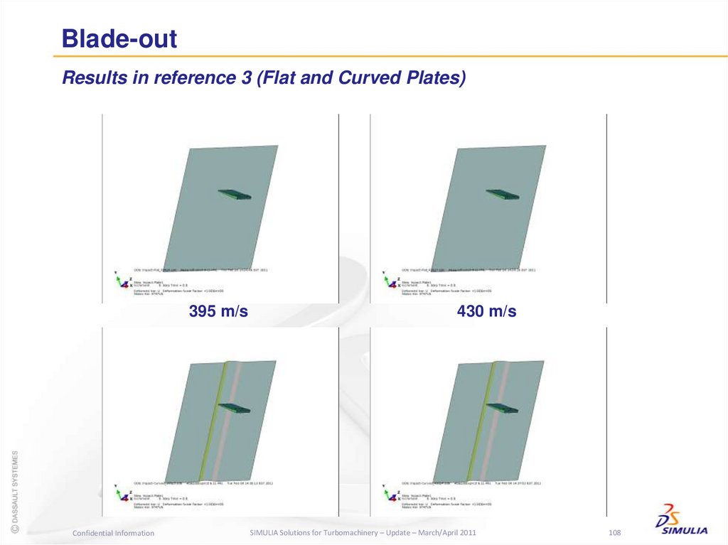
conjunction with Sales & Customer Support
Feed into the Product Strategy and R&D plans
Jack Cofer, Industry Lead, Turbomachinery
Update: September 2010
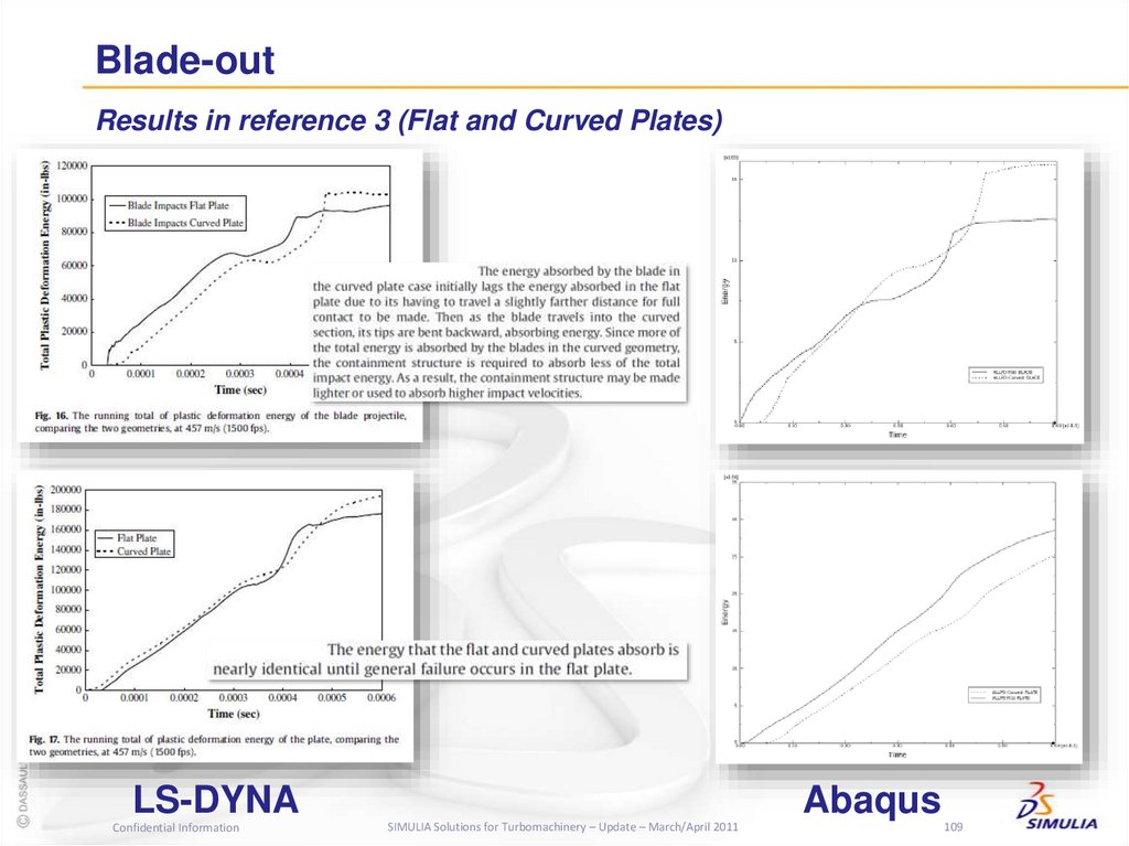
This document
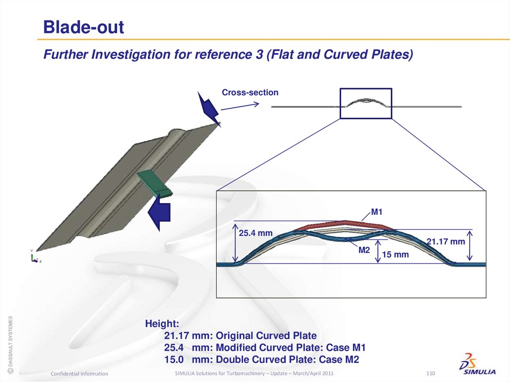
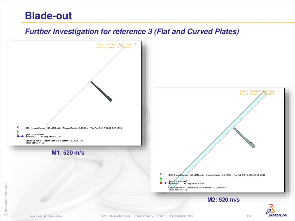
Key elements of the roadmap:
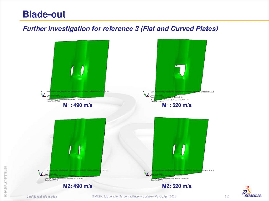
Competitive assessment
Requirements list – what to do to increase our
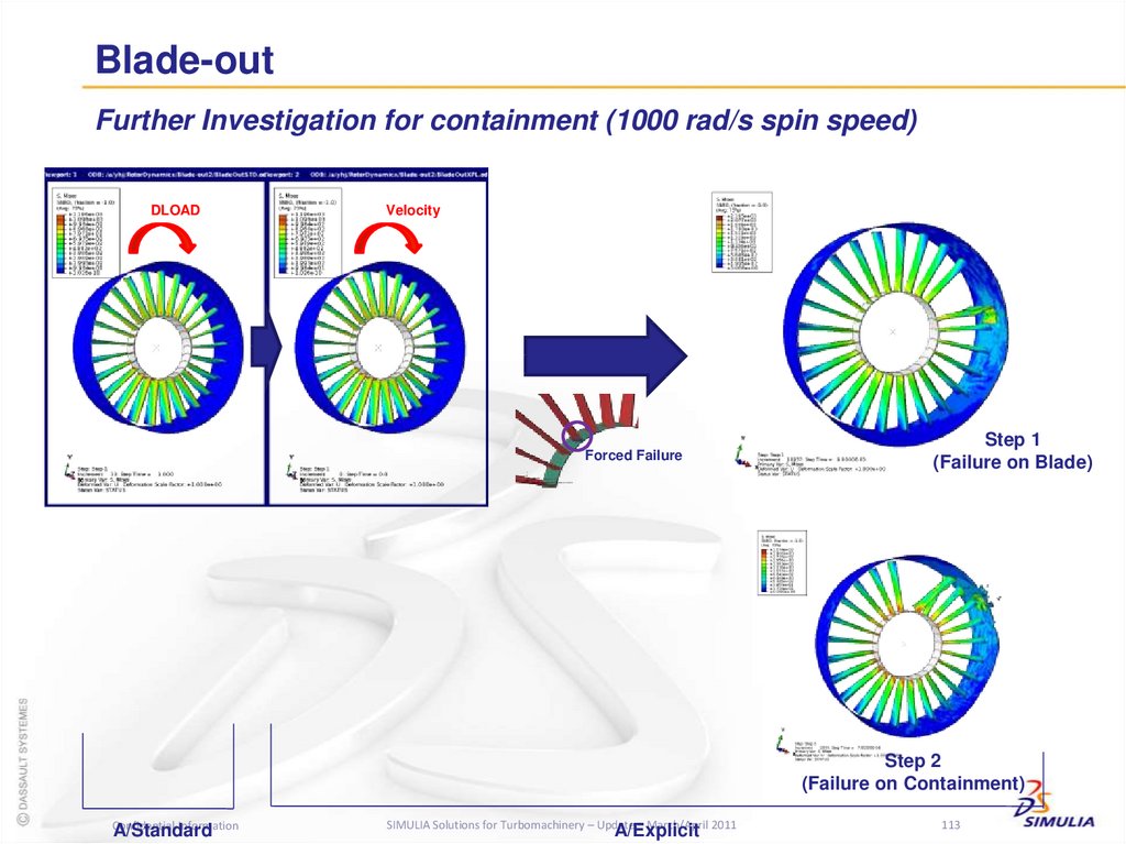
competitiveness (based on customer input)
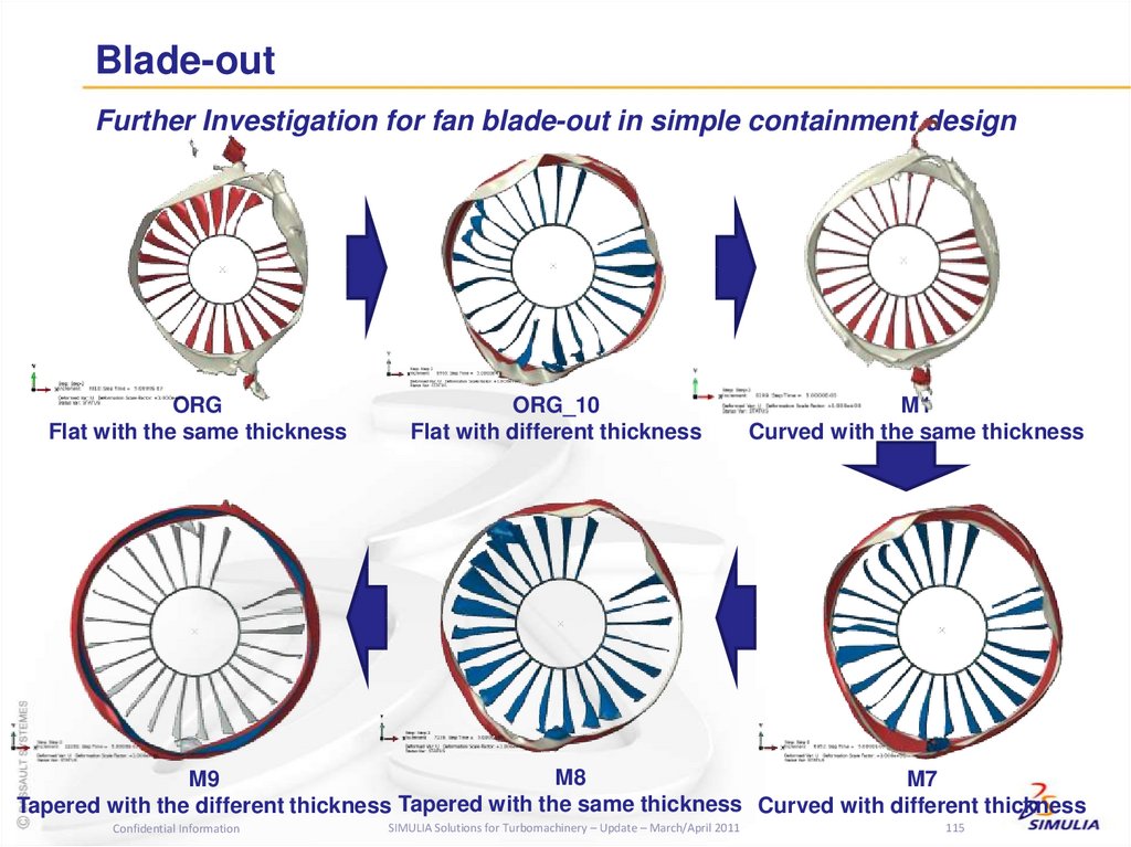
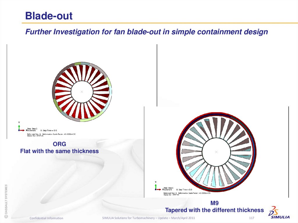
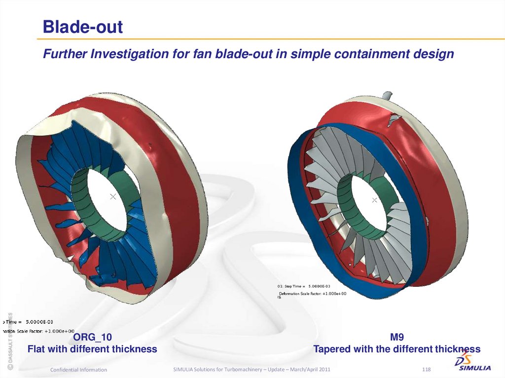
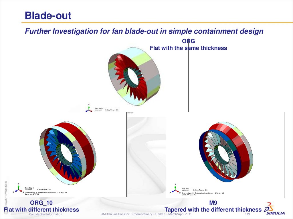
Alliance landscape
Key customer engagements
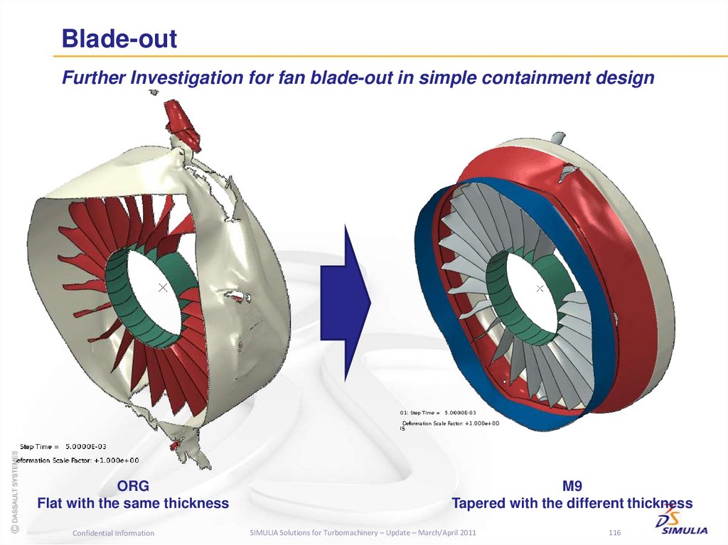
DASSAULT SYSTEMES SIMULIA CORP. CONFIDENTIAL
SIMULIA Technical Marketing
Future roadmaps being planned:
Blade stress and vibration analysis,
aero/mechanical MDO
To be submitted in September 2011
General usability for turbo workflows
Fracture and failure (XFEM)
Thermal analysis and cavity radiation heat transfer
Confidential Information
SIMULIA Solutions for Turbomachinery – Update – March/April 2011
6
6. Future Simulation Roadmaps
Abaqus Enhancements for Turbomachinery in ProgressRotordynamics
Plug-in to automatically generate Campbell diagrams – see Abaqus Answer #4721
Plug-in to enable direct import of bearing coefficients from ROMAC bearing codes THPAD and
SQFDAMP (Target completion: May 2011)
6.10-EF (Nov. 2010) and 6.11 (June 2011): Improvements to direct matrix input capability to
enable import of fully generalized stiffness, mass, and damping matrices (including
non-symmetric, frequency-dependent, cross-coupled dynamic coefficients)
6.12 (June 2012): Improved capability for distributed load definition (DLOAD) to provide the
capability to define loads with respect to a stationary reference frame with frequency
dependency and perform rotordynamic analyses on fully detailed 3-D solid models created
within (or imported into) Abaqus/CAE
6.12+: Expanded plug-in for more plots (interference diagrams, orbit depiction, critical speed
maps, and unbalance response plots)
Training class: December 2011
Mapping
Undocumented in 6.10-EF for testing with full release in 6.11 (June 2011): Full interactive
capability in /CAE to map spatially varying surface data (pressure, temperature, film
coefficients, etc.) from 3rd party products into Abaqus attribute definitions (b.c.’s, loads, shell
thickness, etc.) and visualize it
6.12 (June 2012): Full contour visualization in /CAE without running datacheck with pre.exe
Cavity radiation
6.10: New adaptive view factor calculation to dramatically improve accuracy
Long-term: looking at revamping the whole method to make many improvements
Confidential Information
SIMULIA Solutions for Turbomachinery – Update – March/April 2011
7
7. Abaqus Enhancements for Turbomachinery in Progress
UVA Rotating Machinery and Controls Laboratory(ROMAC) Industrial Program
In June 2010, SIMULIA joined the University of Virginia Rotating Machinery and
Controls Laboratory (ROMAC) Industrial Program.
This program supports cooperative research efforts conducted by faculty, staff,
and students in the Mechanical and Aerospace Engineering Department and
the Electrical Engineering Department at the University of Virginia.
The ROMAC Industrial Program emphasizes theoretical and experimental
research in general areas of rotordynamics, turbomachinery, structural
dynamics, magnetic bearings, the application of automatic controls to the
dynamics of rotating machinery, internal incompressible flows, the coupling of
internal flows to the dynamics of rotating machinery, fluid film bearings, and
seals.
The interaction between industry and university professionals through the
medium of ROMAC provides the university researchers with an understanding
of practical industrial problems with rotating machinery while the industrial
participants obtain very timely research results and access to a full suite of
world-leading rotordynamics and bearing analysis codes.
More than 40 companies are currently members of the Industrial Program, most
of whom are listed on the ROMAC web site at
http://www.virginia.edu/romac/current_members.htm.
Confidential Information
SIMULIA Solutions for Turbomachinery – Update – March/April 2011
8
8. UVA Rotating Machinery and Controls Laboratory (ROMAC) Industrial Program
Joint Rotordynamics Work with ROMACDr. Youngwon Hahn is currently working with two Ph.D. students at ROMAC. This
work will be reported at the ROMAC Annual Meeting in June 2011.
Project #1: Create an Abaqus/CAE plug-in to allow automated import of bearing
properties from the ROMAC bearing codes
Focused initially on tilting pad oil film bearings (commonly used in gas and steam turbines) - squeeze
film damper bearings (commonly used in aircraft engines) to be added later.
The plug-in will provide two options:
1. Direct import of bearing properties (stiffness, damping coefficients) from the ROMAC codes
THBRG, THPAD, and MAXBRG so that the user doesn't have to manually enter and convert them
2. Manual input of individual bearing stiffnesses and damping coefficients in the plug-in GUI
Status: In testing, to be released May 2011
Project #2: Provide reference data and further insight for development efforts that will
improve the ability of Abaqus to handle full 3D non-axisymmetric rotor models,
including the rotor blades.
ROMAC will perform their own rotordynamics analyses and generate mode shape plots for both 3D
axisymmetric and non-axisymmetric rotor models to compare to SIMULIA models and results using
Abaqus.
Status: 3D bladed wheel models created by SIMULIA and sent to ROMAC, 3D rotor models under
development.
In the long term, we will investigate ways in which SIMULIA’s Isight software can be
used to automate the rotordynamics analysis simulation process to achieve optimal
designs for rotor/bearing systems.
Confidential Information
SIMULIA Solutions for Turbomachinery – Update – March/April 2011
9
9. Joint Rotordynamics Work with ROMAC
Abaqus 6.11 PreviewSIMULIA Technical
Confidential
Marketing
Information
SIMULIA Solutions for Turbomachinery – Update – March/April 2011
11
10. Major RFE Status (Siemens)
GPGPU AccelerationDirect solver acceleration using
GPGPU’s
Speed-ups of 2-3x have been
observed
Benefits generally limited to larger
problems > 1M
Confidential Information
SIMULIA Solutions for Turbomachinery – Update – March/April 2011
12
11. Abaqus 6.11 Preview
Smoothed Particle Hydrodynamics (SPH)Suitable for large deformation problems
involving damage/fragmentation
Increases competitiveness in aerospace
and defense industries
Limited parallel scalability in the first
release
Ballistic impact
Fluid flowing
through a fan
Confidential Information
SIMULIA Solutions for Turbomachinery – Update – March/April 2011
13
12. GPGPU Acceleration
Contact EnhancementsContact pressure error indicators
increase confidence in results quality
Edge-surface contact expands the
class of problems that can be solved
robustly
Error indicators
Edge-surface contact
Confidential Information
SIMULIA Solutions for Turbomachinery – Update – March/April 2011
14
13. Smoothed Particle Hydrodynamics (SPH)
Conveyer BeltSpecialized technique for simulating continuous processes
Limited to periodic geometries
Unique in the industry
Trigger plane
4
C
B
1
I
A
Consumer product packaging
Confidential Information
SIMULIA Solutions for Turbomachinery – Update – March/April 2011
15
D
5
O
14. Contact Enhancements
Parallel Frequency Response SolverTargeted towards automotive NV market
Supports SMP w/ up to 24 cores
Provides class-leading performance
Analysis time [hours]
450
400
350
300
250
200
150
100
50
0
6.10EF
6.11
6.11
6.11
6.11
6.11
6.11
(1-core) (1-core) (2-core) (4-core) (8-core) (16-core) (24-core)
Confidential Information
SIMULIA Solutions for Turbomachinery – Update – March/April 2011
16
15. Conveyer Belt
MultiphysicsNew solution procedures for:
Thermal-electrical-structural (ETS)
Low-frequency electromagnetics (EM)
Sequential thermal-stress following EM
Applications span the range of industries
Spot welding
Confidential Information
SIMULIA Solutions for Turbomachinery – Update – March/April 2011
17
16. Parallel Frequency Response Solver
CAD Interfaces• CATIA V5 Bidirectional Associative Interface
• CATIA parameters can be modified from Abaqus/CAE
• Model updated automatically
• Support for CATIA V5 R20
CAD geometry and parameters
export to Abaqus/CAE
Updated parameters
export to CATIA V5
Confidential Information
SIMULIA Solutions for Turbomachinery – Update – March/April 2011
18
17. Multiphysics
19Substructures
Continuation of 6.10-EF project
Support for:
Substructure load cases
Substructure load
Improved display
Substructure statistics query
Confidential Information
SIMULIA Solutions for Turbomachinery – Update – March/April 2011
19
18. CAD Interfaces
Mid-surfacing Enhancements• Reduce picking needed to create mid-surface
• Improved robustness
• Offset operation performance
• Feature regeneration
• Enhanced heuristics for Extend and Blend geometry tools
• New tool for partitioning faces by edge projection
Confidential Information
SIMULIA Solutions for Turbomachinery – Update – March/April 2011
20
19. Substructures
Tet MeshingMinimum element size specification
Tetrahedral element size growth control for interior volume
Improved quality and robustness
Control deviation between boundary mesh and surface geometry
Reduced likelihood of creating short element edges
Better gradation on surface meshes
Confidential Information
SIMULIA Solutions for Turbomachinery – Update – March/April 2011
21
20. Mid-surfacing Enhancements
Mesh Editing• New mesh edit functions
• Merge/subdivide elements
• Grow/collapse short element edges
• Bottom-up meshing
• Now available for orphan meshes
• Generate elements by offsetting
• Additional options for extrude method
Confidential Information
SIMULIA Solutions for Turbomachinery – Update – March/April 2011
22
21. Tet Meshing
Mapping CapabilityInterface for:
Importing spatially varying point cloud field data
Applying data sets as loads, predefined fields and interactions
Examples:
Pressure, temperature & film coefficients
Shell thickness, density
Import data using
Text files & spreadsheets
Existing Abaqus output database
Mapping options & controls
Default value, algorithm, search tolerance
Confidential Information
SIMULIA Solutions for Turbomachinery – Update – March/April 2011
23
22. Mesh Editing
Assembled Fasteners• Capabilities for realistic modeling of fasteners
• Create Template model
• Separate from actual analysis model.
• Contains surfaces, constraints and connectors
• Assign to a region
• Attachment points, orientations, and surfaces
specified to create an “assembled fastener”.
• Allows specification of a calibration script.
3 plate template model
Confidential Information
SIMULIA Solutions for Turbomachinery – Update – March/April 2011
24
23. Mapping Capability
Analysis CoverageInterface for Anisotropic Hyperelasticity
Highly anisotropic and nonlinear elastic
material behavior
Model soft biological tissues and
fiber-reinforced elastomers
Abaqus/CFD
Distributions to velocity
Inlet, outlet and wall BC
Confidential Information
SIMULIA Solutions for Turbomachinery – Update – March/April 2011
25
24. Assembled Fasteners
Abaqus Topology Optimization Module (ATOM)Topology optimization
Modify stiffness
Good for evolving optimum shape
Shape optimization
Moves nodes
Good for fine tweaking of shape
Both support:
Contact
Geometric non-linearity
Nonlinear materials
Specify problem
Write .inp file
Modify .inp file
Standard / Explicit
No
Shape or Topology
Optimization
components
Postprocess
Final Solution ?
Visualize
Smooth output
Export to CAD
Confidential Information
SIMULIA Solutions for Turbomachinery – Update – March/April 2011
26
25. Analysis Coverage
Visualization• Contour plots on beam sections
• Available for Box, Rectangle, Circle, Pipe, I and L sections
• New ‘BEAM_STRESS’ field output variable
• SF and SM required
• View cuts enabled with beam profile rendering
Confidential Information
SIMULIA Solutions for Turbomachinery – Update – March/April 2011
27
26. Abaqus Topology Optimization Module (ATOM)
Free Body Diagram Enhancements• Section force/moment history output
• Section force/moment display on
multiple view cuts
• Multiple free bodies on a single view
cut
Confidential Information
SIMULIA Solutions for Turbomachinery – Update – March/April 2011
28
27. Visualization
Isight 5.5 PreviewSIMULIA Technical
Confidential
Marketing
Information
SIMULIA Solutions for Turbomachinery – Update – March/April 2011
29
28. Free Body Diagram Enhancements
Isight 5.5 – Desktop Process Integration & OptimizationIntuitive graphical interface
Integrate applications and automate
simulation processes using components
Full suite of powerful exploration tools
Optimization
Design for Six Sigma
Design of Experiments
Reliability and Robustness
Approximation models
Nested exploration / MDO
Interactive data visualization for
post processing of multi-run jobs
and results interpretation
Grid execution with SEE
Helps identify the best design
Confidential Information
SIMULIA Solutions for Turbomachinery – Update – March/April 2011
30
29. Isight 5.5 Preview
Isight 5.5 EnhancementsModel & Simulation Integration
Dymola component
Model comparison tool
Optimization
MISQP
Custom exploration strategy
Postprocessing
Overlaid constraints graph
Carpet charts
Confidential Information
SIMULIA Solutions for Turbomachinery – Update – March/April 2011
31
30. Isight 5.5 – Desktop Process Integration & Optimization
Isight 5.5 Enhancements: Model & Simulation IntegrationDymola Component allows users to modify a Dymola input file, simulate the Dymola
model, and extract the results from the Dymola output file
Model Comparison Tool allows users to quickly compare Isight sim-flow models in
order to determine differences in the problem definition, sim-flow, and coupledsimulation models
Parameters of the
selected component
Parameters and initial
condition of variables
of the whole model
Mapping of Isight
parameters to the
Dymola model
parameters
User can search for
an input parameter
by its name
Confidential Information
SIMULIA Solutions for Turbomachinery – Update – March/April 2011
32
31. Isight 5.5 Enhancements
Isight 5.5 Enhancement: Custom Exploration StrategyPython/Jython, Java script mode offers complete flexibility to impose any
desired logic on the optimization process
Leverage existing DOE, Optimization, Approximation and Monte Carlo
run single points
run plans
store a design
change the design
restore a design
Confidential Information
SIMULIA Solutions for Turbomachinery – Update – March/April 2011
33
32. Isight 5.5 Enhancements: Model & Simulation Integration
Isight 5.5 Enhancement: Mixed-Integer SequentialQuadratic Programming Algorithm (MISQP)
• MISQP is a cutting edge
optimization technique in Isight for
mixed real and integer variables
developed by Klaus Schittkowski.
Excellent benchmark results:
#function calls for each problem and each method
• This algorithm combines the SQP
technique used in NLPQL with a
branch-and-bound technique for
integers.
• Behaves identically to NLPQL for
problems without integer variables.
white: optimal
Confidential Information
SIMULIA Solutions for Turbomachinery – Update – March/April 2011
Grey: feasible
red: fail
34
33. Isight 5.5 Enhancement: Custom Exploration Strategy
2011 SIMULIA Customer ConferenceAdvanced Seminars - May 16; Conference - May 17-19, 2011
Barcelona, Spain
138 abstracts received
Resulting in 80+ Customer Papers / Presentations
Representing all industries and SIMULIA products; including
Abaqus, Isight, and SLM
Goal of 200+ Customer Attendees and 20+ Partner Exhibitors
6 Industry Special Interest Groups (including Turbomachinery)
4 Advanced Seminars
5 General Lectures
2 Customer Keynotes
Details at: www.simulia.com/scc2011
Confidential Information
SIMULIA Solutions for Turbomachinery – Update – March/April 2011
35
34. Isight 5.5 Enhancement: Mixed-Integer Sequential Quadratic Programming Algorithm (MISQP)
For more informationwww.simulia.com/solutions/turbomachinery.html
New site still under development, new content added periodically
SIMULIA Customer Conference paper references and online videos
Case studies, tech briefs, flyers, webinars
Eblade webinar, September 2010
New Features in Isight/SEE 4.5, September 2010
New Features in Abaqus 6.10-EF, January 2011
Replays now available at www.simulia.com
Jan/Feb 2010 issue of INSIGHTS magazine
Latest issue of Realistic Simulation News
Download at www.simulia.com/RSN
ASME and other conference papers on Abaqus
and Isight applications for turbomachinery
List provided upon request (just updated)
Regional User Meetings (RUMs)
Schedules posted at simulia.com/events/rums.html
Contact Jack Cofer, Industry Lead for
Turbomachinery, at jack.cofer@3ds.com
Confidential Information
SIMULIA Solutions for Turbomachinery – Update – March/April 2011
36
35. 2011 SIMULIA Customer Conference
Turbomachinery Applications using AbaqusYoungwon Hahn
Ver. OCT 2010
Confidential Information
SIMULIA Solutions for Turbomachinery – Update – March/April 2011
37
36. For more information
Who Is Dr. Youngwon Hahn?Confidential Information
SIMULIA Solutions for Turbomachinery – Update – March/April 2011
38
37. Turbomachinery Applications using Abaqus
OverviewRotordynamics
Gyroscopic Effect
Bearing Modeling
Frequency Extraction and Frequency Response
Campbell Diagram Plug-in
Other Plug-in in development (including interface with ROMAC bearing code)
Substructure
Coupled Structural-Acoustic Analysis
Blade Analysis
Modeling in A/CAE
Cyclic Symmetric Model
Modal Analysis
Stress Analysis
New Mapping Capability in A/CAE (6.11)
XFEM
Displacement Analysis (i.e. untwist) for given pre-loading condition
Bird Strike Analysis
Lagrangian Approach
SPH: New functionality in 6.11 (in-progress)
Blade-out Analysis
Case Study of Blade Containment
Confidential Information
SIMULIA Solutions for Turbomachinery – Update – March/April 2011
39
38. Who Is Dr. Youngwon Hahn?
RotordynamicsConfidential Information
SIMULIA Solutions for Turbomachinery – Update – March/April 2011
40
39. Overview
RotordynamicsGyroscopic Effect
Abaqus provides two approaches for gyroscopic effect.
Eulerian approach
This technique was required by a tire application.
User can apply transport velocity as a spin speed in steady state transport procedure in
order to obtain gyroscopic effect for the spinning structure.
This requires axi-symmetric model which was created by special modeling technique
called symmetric model generation (SMG). SMG requires a prior 2-D model result.
This approach is recommended for rotordynamic analysis now.
SMG
Apply spin speed with *transport velocity
in steady state transport procedure
Confidential Information
SIMULIA Solutions for Turbomachinery – Update – March/April 2011
41
40. Rotordynamics
Gyroscopic EffectLagrangian approach
General approach.
User can apply body force as the function of the spin speed in general static procedure
in order to obtain gyroscopic effect for the spinning structure.
– DLOAD with CENTRIF and CORIO load type is supported as a body force.
CORIO load type, one of body forces, only supports solid and truss elements now.
The body force DLOAD is calculated in moving reference frame.
– The whirl frequency can be obtained by manual calculation of result frequency and applied spin
speed.
This approach is not recommended now since subsequent steady state dynamic
analysis is not applicable.
We are planning to enhance this method in 6.12.
Apply spin speed with CENTRIF and CORIO load type
in general static procedure
Confidential Information
SIMULIA Solutions for Turbomachinery – Update – March/April 2011
42
41. Rotordynamics
Bearing ModelingBearing is a flexible component to support shaft.
Bearing has stiffness and damping coefficient
Abaqus provides two types of element for bearing modeling.
Spring and Dashpot elements
– Kxx, Kzz, Cxx or Czz is supported
– Frequency dependency is supported
Connector elements with elastic and damping behavior
– Kxx, Kxz, Kzx, Kzz, Cxx or Czz is supported.
– Frequency dependency is supported only for Kxx, Kzz, Cxx, and Czz.
We are planning to enhance this capability in 6.12
Confidential Information
SIMULIA Solutions for Turbomachinery – Update – March/April 2011
43
42. Rotordynamics
Frequency Extraction and Frequency ResponseReal frequency extraction
Lanczos and AMS solver is supported.
AMS (Automatic Multi-level Substructuring) method
– Well-suited to very large systems where a large subset of eigenvalues are needed.
– The finite element model is projected onto a reduced multi-level substructure modal space to
solve a global eigenproblem.
Complex frequency extraction
Prior real frequency extraction step is required, since projection method is used
for complex frequency extraction step.
Frequency response analysis
Steady-state dynamic procedure is supported.
Direct method and subspace-based method are
supported for gyroscopic effect.
Unbalanced load can be considered
with *CLOAD, loadcase=# keyword.
Confidential Information
SIMULIA Solutions for Turbomachinery – Update – March/April 2011
Red : SSD, Subspace
Blue : SSD, Direct
44
43. Rotordynamics
Frequency Extraction and Frequency ResponseComparison with reference paper
L
2r
simply supported
Reference Results*
σ=r/(2L)
*T.C. Gmur and J.D. Rodrigues, “Shaft Finite element for Rotor dynamics
Analysis,” ASME J. Vib. Acoust. 113 (1993) 482-493
Confidential Information
SIMULIA Solutions for Turbomachinery – Update – March/April 2011
50
44. Rotordynamics
Frequency Extraction and Frequency ResponseComparison with reference paper
Dimensionless critical forward/backward speed
Ratio
0.02
0.04
0.06
0.08
backward
3.1498
3.0790
3.0059
2.9254
reference (1)*
3.1362
3.0851
3.0111
2.9244
reference (2)*
3.1252
3.0792
3.0116
2.9313
reference (3)*
3.1253
3.0796
3.0125
2.9328
Forward
3.1617
3.1226
3.0929
3.0583
reference (1)*
3.1482
3.1292
3.0976
3.0539
reference (2)*
3.1373
3.1240
3.1016
3.0696
reference (3)*
3.1374
3.1246
3.1027
3.0715
0.1
2.8418
2.8329
2.8455
2.8475
3.0185
2.9991
3.0282
3.0311
3,20
3,10
backward
reference (1)
reference (2)
3,00
reference (3)
forward
2,90
reference (1)
reference (2)
2,80
reference (3)
2,70
*T.C. Gmur and J.D. Rodrigues, “Shaft Finite element for Rotor
dynamics Analysis,” ASME J. Vib. Acoust. 113 (1993) 482-493
Confidential Information
0
0,02
0,04
0,06
0,08
SIMULIA Solutions for Turbomachinery – Update – March/April 2011
0,1
0,12
51
45. Rotordynamics
Frequency Extraction and Frequency ResponseComparison with analytical solution
ENCASTRE
RIGID
BODY
Shaft assumed Massless, but Flexible
Disk is assumed Rigid
Units in m, Kg, N, s
Radius of Disk has been chosen such
that:
It = ml3/3
Where
It = Disk transverse moment of inertia
m = Disk mass
l = Shaft length
E = 2.1e11 Pa
Disk density = 7800 kg/m^3
2R = 0.583124
Confidential Information
SIMULIA Solutions for Turbomachinery – Update – March/April 2011
52
46. Introduction
RotordynamicsFrequency Extraction and Frequency Response
Comparison with analytical solution
@ 400
rad/s
Classical Result*
Abaqus
Backward
Forward
Backward
Forward
1
51.6
112.9
53.507
110.69
2
268.3
334.4
264.08
331.80
@ 1400
rad/s
Classical Result*
Abaqus
Backward
Forward
Backward
Forward
1
23.3
170.9
24.85
164.31
2
234
541.1
237.49
535.2
*J.P. Den Hartog, “Mechanical Vibrations,” Dover Publication, Inc, New York, 1985
Confidential Information
SIMULIA Solutions for Turbomachinery – Update – March/April 2011
53
47. Rotordynamics
Frequency Extraction and Frequency ResponseComparison with ROMAC results
Shaft: L=50, Do=2, Di=0.1
Disk: L=2, Do=18, Di=2
Bearing location: 4 inches away from the each end
E=30e6, Poisson’s ratio=0.3, Density=0.284(lb/in2)/386.4 = 7.35e-4 (lbm/in2)
Three cases: one disk, three disks, and five disks
5
4
4
9
Bearing
Confidential Information
SIMULIA Solutions for Turbomachinery – Update – March/April 2011
54
48. Rotordynamics
Frequency Extraction and Frequency ResponseComparison with ROMAC results
With uncoupled bearing (no Kxy/Kyx)
Kxx = 1000, Kzz = 2000
Cxx = 300, Czz = 400
One Disk Rotor
ROMAC Abaqus ERROR
30.35 (B)
30.30
0.18%
30.37 (F)
30.31
0.19%
172.00 (F) 170.88 0.65%
114.05 (B) 114.17 0.11%
544.83 (F) 547.56 0.50%
544.17 (B) 546.95 0.51%
550.33 (B) 553.40 0.56%
557.17 (F) 560.10 0.53%
Damped Natural Frequency
Three Disks Rotor
ROMAC Abaqus
ERROR
19.23 (B)
19.31
0.38%
21.02 (F)
21.07
0.25%
72.57(B)
73.06
0.67%
89.15 (F)
89.48
0.37%
134.47 (B) 135.51
0.78%
163.25 (F) 164.40
0.70%
177.83 (B) 178.34
0.28%
227.17 (F) 226.92
0.11%
Five Disks Rotor
ROMAC Abaqus
ERROR
15.55 (B)
15.66
0.75%
19.70 (F)
19.77
0.33%
67.62 (F)
68.15
0.79%
56.90 (B)
57.50
1.06%
110.15 (B) 111.42
1.15%
138.35 (F) 139.37
0.74%
148.38 (B) 149.72
0.90%
201.67 (F) 204.62
1.46%
Log Dec
One Disk Rotor
Three Disks Rotor
Five Disks Rotor
ROMAC Abaqus ERROR ROMAC Abaqus ERROR ROMAC Abaqus ERROR
0.4381 0.4321 1.36% 0.5924 0.5881 0.73% 0.6599 0.6587 0.19%
0.3281 0.3236 1.37% 0.7368 0.7282 1.16% 1.1410 1.1260 1.31%
0.0765 0.0761 0.53% 0.4321 0.4267 1.24% 0.6927 0.6892 0.51%
0.1397 0.1372 1.76% 0.2994 0.2983 0.35% 0.5834 0.5808 0.44%
0.0641 0.0629 1.81% 0.2869 0.2826 1.50% 0.5903 0.5877 0.44%
0.0505 0.0496 1.68% 0.1284 0.1260 1.87% 0.4162 0.4199 0.89%
0.0516 0.0506 1.89% 0.1518 0.1520 0.15% 0.4474 0.4376 2.18%
0.0503 0.0494 1.85% 0.0625 0.0622 0.45% 0.5497 0.5505 0.14%
Solver Difference
Abaqus: Projection method. Frequency extraction step is required.
ROMAC: Direct method (Complex Hessenberg QR algorithm) in EISPACK
Confidential Information
SIMULIA Solutions for Turbomachinery – Update – March/April 2011
55
49. Rotordynamics
Frequency Extraction and Frequency ResponseComparison with ROMAC results
With uncoupled bearing (no Kxy/Kyx)
Kxx = 1000, Kzz = 2000
Cxx = 300, Czz = 400
Confidential Information
SIMULIA Solutions for Turbomachinery – Update – March/April 2011
56
50. Rotordynamics
Frequency Extraction and Frequency ResponseComparison with ROMAC results
With uncoupled bearing (no Kxy/Kyx)
Kxx = 1000, Kzz = 2000
Cxx = 300, Czz = 400
Abaqus shows additional mode (torsional mode)
Abaqus
Confidential Information
ROMAC
mode
SIMULIA Solutions for Turbomachinery – Update –Zero
March/April
2011
57
51. Rotordynamics
Frequency Extraction and Frequency ResponseLoad Definition (unbalance load)
1 oz-in at 0,90, and180 degrees (X-axis is 0 degree)
Unbalanced mass for loading
(0,90,180 degrees)
Bearing property
Bearing property
Kxx
38601.54
57810.68
75565.91
91934.54
105787.4
117891.2
128550.6
139211.9
Confidential Information
Kxz
0
0
0
0
0
0
0
0
Kzx
0
0
0
0
0
0
0
0
Kzz
52588.27
68011.77
83794.3
99067.23
112254
123904.6
134217
144593
Cxx
544.5408
449.5349
391.7378
350.412
315.4584
286.6295
262.4451
243.596
Cxz
0
0
0
0
0
0
0
0
Czx
0
0
0
0
0
0
0
0
SIMULIA Solutions for Turbomachinery – Update – March/April 2011
Czz
496.1638
474.8226
404.688
358.4907
321.0936
290.8449
265.7449
246.2656
58
52. Rotordynamics
Simple Rotor (Three Disks)Frequency Extraction and Frequency Response
Confidential Information
SIMULIA Solutions for Turbomachinery – Update – March/April 2011
59
53. Rotordynamics
Campbell Diagram Plug-in (ANSWER 4721)Newly developed A/Viewer Plug-in for rotordynamic application
Confidential Information
SIMULIA Solutions for Turbomachinery – Update – March/April 2011
60
54. Rotordynamics
Campbell Diagram Plug-inNewly developed A/Viewer Plug-in for rotordynamic application
Reference curve
Confidential Information
SIMULIA Solutions for Turbomachinery – Update – March/April 2011
61
55. Rotordynamics
Other Plug-in in DevelopmentPlug-in to import bearing property from ROMAC Bearing Code
(THBRG, THPAD, and MAXBRG)
Calculate Coefficients
Manual Input
Read from File
Confidential Information
SIMULIA Solutions for Turbomachinery – Update – March/April 2011
62
56. Rotordynamics
Other Plug-in in DevelopmentPlug-in to import bearing property from
ROMAC Bearing Code (THBRG, THPAD,
and MAXBRG)
Calculate Coefficients
Read input file for bearing code
Run the ROMAC bearing code
– THPAD
– THBRG
Save the bearing coefficient to Abaqus input
file format.
Confidential Information
SIMULIA Solutions for Turbomachinery – Update – March/April 2011
63
57. Rotordynamics
Other Plug-in in DevelopmentPlug-in to import bearing property from
ROMAC Bearing Code (THBRG, THPAD,
and MAXBRG)
Manual Input
Bearing property manual input
Save the bearing coefficient to Abaqus input
file format.
Confidential Information
SIMULIA Solutions for Turbomachinery – Update – March/April 2011
64
58. Rotordynamics
Other Plug-in in DevelopmentPlug-in to import bearing property from
ROMAC Bearing Code (THBRG, THPAD,
and MAXBRG)
Read from File
Read input file for bearing code
Run the ROMAC bearing code
– THPAD
– THBRG
– MAXBRG
Save the bearing coefficient to Abaqus input
file format.
Confidential Information
SIMULIA Solutions for Turbomachinery – Update – March/April 2011
65
59. Simple Rotor (Three Disks)
RotordynamicsSubstructure
Abaqus provides substructuring capability (superelement).
Gyroscopic effect is handled as a damping matrix.
Abaqus supports reduced damping matrix generation for substructure
Viscous damping
Viscous damping matrix can be unsymmetric due to coriolis forces
Structural damping
Confidential Information
SIMULIA Solutions for Turbomachinery – Update – March/April 2011
66
60. Rotordynamics
SubstructureExample: Rotor-bearing system with support structure.
Modal analysis considering spin speed (261 rad/s)
Bearing with elastic behavior is defined between shaft and support structure
Spin
Shaft
Support Structure
Support Structure
Fixed
Confidential Information
SIMULIA Solutions for Turbomachinery – Update – March/April 2011
67
61. Rotordynamics
SubstructureRotor-bearing system with support structure.
Three different cases: full model, support substructure, and shaft substructure
Case I
Full Model
Substructure
Case III
Shaft Substructure
Case II
Support Substructure
Substructure
Confidential Information
SIMULIA Solutions for Turbomachinery – Update – March/April 2011
68
62. Rotordynamics
SubstructureRotor-bearing system with support structure.
Three different cases: full model, support substructure, and shaft substructure
Number
1
2
3
4
5
6
Case I
Case II
Case III
Number
Diff. with Case 1 in IM Number
Diff. with Case 1 in IM
RE
IM
RE
IM
RE
IM
-1.38E-08 85.214
1
1.23E-11 87.371
2.53%
1
-7.60E-11 85.214
0.00%
1.46E-08 87.207
2
-1.26E-11 89.54
2.68%
2
7.44E-11 87.207
0.00%
-1.59E-09 166.91
3
4.81E-11 167.8
0.53%
3
3.63E-11 166.91
0.00%
2.19E-09 172.63
4
-4.90E-11 173.62
0.57%
4
-3.63E-11 172.63
0.00%
7.62E-10 338.46
5
1.30E-10 369.37
9.13%
5
-3.87E-11 338.46
0.00%
-2.34E-09 342.72
6
-1.30E-10 373.58
9.00%
6
4.05E-11 342.72
0.00%
Case I: mode 3
Case III : mode 3
Confidential Information
SIMULIA Solutions for Turbomachinery – Update – March/April 2011
Case II : mode 3
69
63. Rotordynamics
SubstructureRotor-bearing system with support structure (refined model)
Three different cases: full model, shaft substructures with 2 and 3 retained nodes
Case I
Full Model
Case V
Shaft Substructure with
3 retained nodes
Case IV
Shaft Substructure with
2 retained nodes
Substructure
Substructure
Retained nodes
Retained nodes
Confidential Information
SIMULIA Solutions for Turbomachinery – Update – March/April 2011
70
64. Rotordynamics
SubstructureRotor-bearing system with support structure.
Three different cases: full model, shaft substructures with 2 and 3 retained nodes
Case IV with 2
Case V with 3
Number
Number retained nodes Diff. with Case 1 in IM Number retained nodes Diff. with Case 1 in IM
RE
IM
RE
IM
RE
IM
1
2.08E-08 81.653
1
-6.70E-12 84.531
3.52%
1
4.18E-12 82.064
0.50%
2
-2.06E-08 83.397
2
7.80E-12 86.492
3.71%
2
-3.89E-12 83.836
0.53%
3
-4.82E-08 169.71
3
-1.30E-11 171.83
1.25%
3
5.41E-12 170.95
0.73%
4
4.54E-08 175.28
4
1.31E-11 177.64
1.35%
4
-6.96E-12 176.66
0.79%
5
2.95E-08 350.5
5
-2.94E-11 408.03
16.41%
5
1.25E-11 354.62
1.18%
6
-2.53E-08 355.29
6
2.89E-11 413.16
16.29%
6
-1.11E-11 359.46
1.17%
Case I
Case I: mode 5
Case V : mode 5
Confidential Information
SIMULIA Solutions for Turbomachinery – Update – March/April 2011
Case IV : mode 5
71
65. Rotordynamics
Coupled Structural-Acoustic AnalysisConfidential Information
SIMULIA Solutions for Turbomachinery – Update – March/April 2011
72
66. Rotordynamics
Coupled Structural-Acoustic AnalysisFrequency Extraction and Frequency Response
Lanczos and AMS solvers support coupled structural-acoustic
analysis.
We have two kinds of architectures: SIM and ADB.
ADB-based Lanczos solver provides fully coupled method.
SIM-based Lanczos and AMS solvers provide project method.
Steady State Dynamic (SSD) analysis can be applied for frequency
response analysis.
POR
SSD, direct
SSD, mode-based
(450-650 Hz)
Direct solution
SSD, mode-based
Mode superposition
SSD, subspace-based
Subspace projection method
SSD, mode-based
(0-1200 Hz)
SSD, direct
Confidential Information
SIMULIA Solutions for Turbomachinery – Update – March/April 2011
73
67. Rotordynamics
Coupled Structural-Acoustic AnalysisCoupled Structural Acoustic Model
Steel
thickness: 1.219 mm
length: 1010 mm
mean radius: 182.56 mm
E: 2.1e5 MPa
Density: 7.8e-6 Kg/mm^3
Poisson’s ratio: 0.3
Aluminum
thickness: 25.4 mm
E: 7.e4 MPa
Density: 2.7e-6 Kg/mm^3
Poisson’s ratio: 0.3
Aluminum
thickness: 25.4 mm
E: 7.e4 MPa
Density: 2.7e-6 Kg/mm^3
Poisson’s ratio: 0.3
free-free boundary condition
Air (Inside)
Density: 1.21e-9 Kg/mm^3
Bulk modulus: 0.14 Mpa
Sound of speed: 340 m/s
Element length <= speed of sound / (n*(max. Freq.)), n= 6~10
Element length set-up: 10 mm for STR (for higher ND)
Confidential Information
SIMULIA Solutions for Turbomachinery – Update – March/April 2011
74
68. Rotordynamics
Coupled Structural-Acoustic AnalysisCoupled Structural Acoustic Model
POR
Result
U
Frequency range:
80-480 Hz
Mode(n,m)**
(4,1)
(4,1)
(3,1)
(3,1)
(5,1)
(5,1)
(2,1)
(2,1)
(6,1)
(6,1)
(5,2)
(5,2)
(6,2)
(6,2)
(4,2)
(4,2)
(7,1)
(7,1)
(7,2)
(7,2)
Mode(p,q,r)***
(0,0,1)
(0,0,2)
Structural Mode
Experiment*
Abaqus
172.7
179.66
173.8
179.66
178.6
185.04
179.1
185.04
232.8
236.11
233.5
236.12
294.8
299.15
297.7
299.15
326.8
329
329.01
328.3
335.93
330.4
335.94
368.6
375.31
370.3
375.31
377
379.29
379.3
444.1
447.65
447.65
471.1
475.74
471.9
475.74
Acoustic Mode
Experiment
Abaqus
172
168.7
343
336.56
Err
4.0%
3.4%
3.6%
3.3%
1.4%
1.1%
1.5%
0.5%
0.7%
2.3%
1.7%
1.8%
1.4%
0.6%
0.8%
1.0%
0.8%
POR
POR
U
** n and m are the mode orders with
respect to the circumference
and length of the shell.
*** p, q and r are the mode orders with
respect to the circumference, radius
and length of the cylindrical
cavity
-1.9%
-1.9%
*S. Boily and F. Charron, “The vibroacoustic response of a
cylindrical shell
structureInformation
with viscoelastic and poroelastic
Confidential
materials,” Applied Acoustics, 58, 1999, pp 131-152
U
SIMULIA Solutions for Turbomachinery – Update – March/April 2011
75
69. Rotordynamics
Blade AnalysisConfidential Information
SIMULIA Solutions for Turbomachinery – Update – March/April 2011
76
70. Rotordynamics
Blade AnalysisModeling in A/CAE
Blade Geometry from Eblade (see appendix for more details)
Confidential Information
SIMULIA Solutions for Turbomachinery – Update – March/April 2011
77
71. Rotordynamics
Blade AnalysisImport Eblade data to A/CAE: Plug-in
Number of section
Number of points
coordinates
The plug-in reads the input files generated from
Eblade and creates the splines shown in next slide.
Confidential Information
SIMULIA Solutions for Turbomachinery – Update – March/April 2011
78
72. Coupled Structural-Acoustic Analysis
Blade AnalysisCreate geometry by Loft
Repeat…
Confidential Information
SIMULIA Solutions for Turbomachinery – Update – March/April 2011
79
73. Coupled Structural-Acoustic Analysis
Blade AnalysisMeshing
Before meshing, do “combine edge” under “Virtual Topology” in “tool” menu.
Confidential Information
SIMULIA Solutions for Turbomachinery – Update – March/April 2011
80
74. Coupled Structural-Acoustic Analysis
Blade AnalysisMeshing
Then, DO NOT check the curvature control in seed to get the same size of mesh.
Confidential Information
SIMULIA Solutions for Turbomachinery – Update – March/April 2011
81
75. Coupled Structural-Acoustic Analysis
Blade AnalysisModeling in A/CAE
Blade Geometry
With “merge” in Assembly level, one new part can be generated.
Confidential Information
SIMULIA Solutions for Turbomachinery – Update – March/April 2011
82
76. Blade Analysis
Modeling in A/CAEFE Model for a Blade Section and Full Model
No curvature control for blade in “seed” menu
Confidential Information
SIMULIA Solutions for Turbomachinery – Update – March/April 2011
83
77. Blade Analysis
Cyclic Symmetric Modelz
76 sectors
Surface “slave”
*SURFACE, NAME=master
*SURFACE, NAME=slave
*TIE, CYCLIC SYMMETRY, NAME=cyclic
slave, master
Confidential Information
SIMULIA Solutions for Turbomachinery – Update – March/April 2011
Surface “master”
84
78. Blade Analysis
Modal AnalysisFrequency extraction capability is supported with Lanczos solver only
for cyclic symmetric model.
One of the output in frequency extraction for cyclic symmetric model is cyclic
symmetry mode number, which is also called “nodal diameter (ND)”
Nodal diameter (ND) indicates the number of waves along the circumference in a
basic response.
Cyclic sector
ND = 0
ND = 1
ND = 2
ND = 3
360° structure
Confidential Information
SIMULIA Solutions for Turbomachinery – Update – March/April 2011
85
79. Blade Analysis
Modal AnalysisFrequency extraction capability is supported with Lanczos solver only
for cyclic symmetric model.
ND number is one of outputs in .dat file.
Abaqus/Viewer has capability to show the modeshape of 360° structure from
cyclic symmetric model.
Cyclic sector
ND = 0
ND = 1
360° structure
Confidential Information
SIMULIA Solutions for Turbomachinery – Update – March/April 2011
86
80. Blade Analysis
Stress AnalysisAfter mapping the temperature
results from the previous analysis,
stress analysis considering
temperature and centrifugal force
is performed.
The bottom surface is fixed.
Sequentially coupled thermalstress analysis is only available
for cyclic symmetric model.
Confidential Information
SIMULIA Solutions for Turbomachinery – Update – March/April 2011
87
81. Blade Analysis
Temperature MappingArea
Blade Analysis
Stress Analysis
Stress analysis after mapping temperature
Temperature Mapping
Temperature from CFD
Temperature
Confidential Information
SIMULIA Solutions for Turbomachinery – Update – March/April 2011
Applied Mapped Temperature
88
82. Blade Analysis
Stress AnalysisStress analysis after mapping temperature
Confidential Information
SIMULIA Solutions for Turbomachinery – Update – March/April 2011
89
83. Blade Analysis
New Mapping Capability with A/CAE in 6.11Sources of the data can be (but are not limited to):
A previous Abaqus analysis
XYZ data
Supports mapping for scalar values for:
Nodes, elements and element faces
Surfaces and Volumes
Confidential Information
SIMULIA Solutions for Turbomachinery – Update – March/April 2011
90
84. Blade Analysis
New Mapping Capability with A/CAE in 6.11Mapping Fields:
A new type of analytical field
Defines the source field data
values
Two input formats are supported
in 6.11
Point Cloud
Odb Mesh
Support for local systems to
localize and orient the
supplied data
Mapping options & controls
Confidential Information
SIMULIA Solutions for Turbomachinery – Update – March/April 2011
91
85. Blade Analysis
New Mapping Capability with A/CAE in 6.11Point Cloud
XYZ Format
Coordinate data associated with
a field value
User supplies X,Y,Z values and a
value for each location to be
mapped
Read from file
Typed in(???)
Grid Format
Also called tabular format in other products
Defines XYZ data based on planes
XY, YZ or XZ
User supplies plane location and a value for each coordinate pair in that plane
Read from file support (see docs for formatting requirements)
Confidential Information
SIMULIA Solutions for Turbomachinery – Update – March/April 2011
92
86. Blade Analysis
New Mapping Capability with A/CAE in 6.11Odb Mesh
Supports mapping from an ODB to
the current model
Nodal, Whole element, or integration
point data
Dissimilar meshes are supported
User selects a viewport with an
open and displayed ODB to indicate
mapping settings
All settings of the viewport will be used
in the mapping
Primary Variable
Step/Increment
Averaging
Section Points (top or bottom)
Etc.
Confidential Information
SIMULIA Solutions for Turbomachinery – Update – March/April 2011
93
87. Blade Analysis
New Mapping Capability with A/CAE in 6.11Confidential Information
SIMULIA Solutions for Turbomachinery – Update – March/April 2011
94
88. Blade Analysis
New Mapping Capability with A/CAE in 6.11Confidential Information
SIMULIA Solutions for Turbomachinery – Update – March/April 2011
95
89. Blade Analysis
New Mapping Capability with A/CAE in 6.11Confidential Information
SIMULIA Solutions for Turbomachinery – Update – March/April 2011
96
90. Blade Analysis
XFEMCrack initiation and propagation in stress analysis
Confidential Information
Von Mises
SIMULIA Solutions for Turbomachinery – Update – March/April 2011
97
91. Blade Analysis
XFEMCrack initiation and propagation in stress analysis
Crack
Confidential Information
SIMULIA Solutions for Turbomachinery – Update – March/April 2011
98
92. Blade Analysis
Displacement Analysis at given pre-loading conditionTo find the initial configuration for manufacturing in case that the
shape in numerical mode has pre-loading stage.
This capability is already requested by geostatic industrial field to
verify that the initial geostatic stress field is in equilibrium with applied
loads and boundary conditions and to iterate, if necessary, to obtain
equilibrium
*GEOSTATIC
In most geotechnical problems a nonzero state of stress exists in the medium.
– This typically consists of a vertical stress increasing linearly with depth, equilibrated by the
weight of the material, and horizontal stresses caused by tectonic effects.
The active loading is applied on this initial stress state.
– Active loading could be the load on a foundation or the removal of material during an
excavation.
Except for purely linear analyses, the response of the system will be different for
different initial stress states.
– This illustrates a point of nonlinear analysis:
Confidential Information
The response of a system to external loading depends on the state of the system when that loading
sequence begins (and, by extension, to the sequence of loading).
The linear analysis concept of superposing load cases does not apply.
SIMULIA Solutions for Turbomachinery – Update – March/April 2011
99
93. Blade Analysis
Displacement Analysis at given pre-loading conditionBlade Application (Centrifugal Force is considered)
Releasing the loading in *STATIC step:
After *GEOSTATIC step
SIMULIA Solutions for Turbomachinery – Update – March/April 2011
100
Initial Configuration
Confidential Information
94. Blade Analysis
Displacement Analysis at given pre-loading conditionBlade Application (Centrifugal Force is considered)
Initial Configuration
(manufacturing configuration)
Final Configuration
(operation configuration)
Releasing the loading in *STATIC step:
After *GEOSTATIC step
SIMULIA Solutions for Turbomachinery – Update – March/April 2011
101
Initial Configuration
Confidential Information
95. Blade Analysis
Blade-out Containment AnalysisConfidential Information
SIMULIA Solutions for Turbomachinery – Update – March/April 2011
102
96. Blade Analysis
Blade-outPreliminaries
Fan Blade Out (FBO) is a requirement by FAA (Federal Aviation
Administration).
In a commercial jet engines, a system must exist which will not allow any
compressor or turbine blade to perforate the engine case in the event that it is
released from a disk during engine operation*.
Due to this requirement, the fan case is the heaviest single component of a jet engine.
The character of a blade off impact is repeatable.
The most severe blade-out occurs when a 1st stage fan blade in a highbypass gas turbine engine is released.
Pre-loading effect should be considered (centrifugal loading).
Spin speed
Fan Blade Out
Disconnecting rigid connection between blade and rotor at a particular time.
High strain dependent material model is necessary.
Simulation Target:
Adequacy of the containment to resist blade penetration
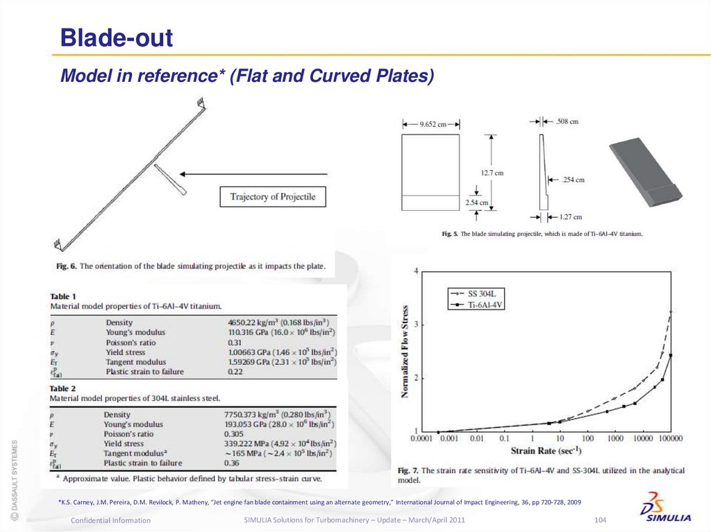
*K.S. Carney, J.M. Pereira, D.M. Revilock, P. Matheny, “Jet engine fan blade containment using an alternate geometry,” International Journal of Impact Engineering, 36, pp 720-728, 2009
Confidential Information
SIMULIA Solutions for Turbomachinery – Update – March/April 2011
103
97. Blade Analysis
Blade-outModel in reference* (Flat and Curved Plates)
*K.S. Carney, J.M. Pereira, D.M. Revilock, P. Matheny, “Jet engine fan blade containment using an alternate geometry,” International Journal of Impact Engineering, 36, pp 720-728, 2009
Confidential Information
SIMULIA Solutions for Turbomachinery – Update – March/April 2011
104
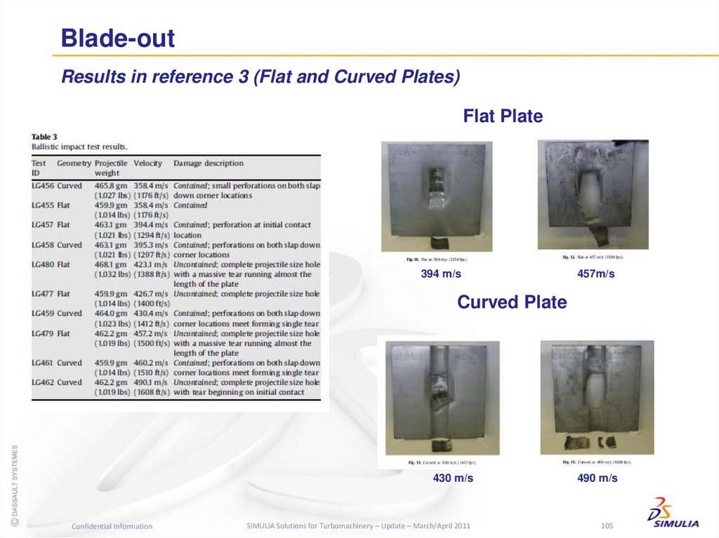
98. Blade Analysis
Blade-outResults in reference 3 (Flat and Curved Plates)
Flat Plate
394 m/s
457m/s
Curved Plate
430 m/s
Confidential Information
SIMULIA Solutions for Turbomachinery – Update – March/April 2011
490 m/s
105
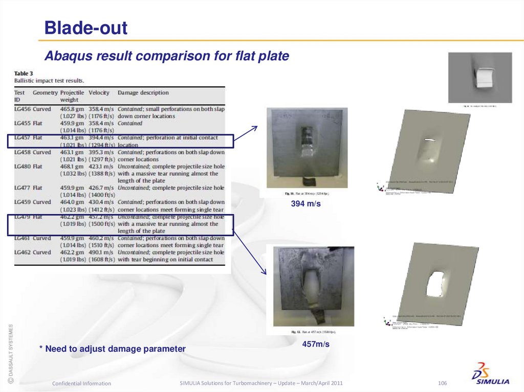
99. Blade Analysis
Blade-outAbaqus result comparison for flat plate
394 m/s
* Need to adjust damage parameter
Confidential Information
457m/s
SIMULIA Solutions for Turbomachinery – Update – March/April 2011
106
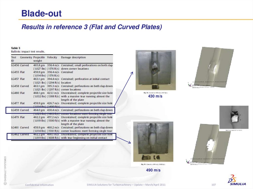
100. Blade Analysis
Blade-outResults in reference 3 (Flat and Curved Plates)
430 m/s
490 m/s
Confidential Information
SIMULIA Solutions for Turbomachinery – Update – March/April 2011
107
101. Blade Analysis
Blade-outResults in reference 3 (Flat and Curved Plates)
395 m/s
Confidential Information
430 m/s
SIMULIA Solutions for Turbomachinery – Update – March/April 2011
108
102. Blade-out Containment Analysis
Blade-outResults in reference 3 (Flat and Curved Plates)
LS-DYNA
Confidential Information
Abaqus
SIMULIA Solutions for Turbomachinery – Update – March/April 2011
109
103. Blade-out
Further Investigation for reference 3 (Flat and Curved Plates)Cross-section
M1
25.4 mm
21.17 mm
M2
15 mm
Height:
21.17 mm: Original Curved Plate
25.4 mm: Modified Curved Plate: Case M1
15.0 mm: Double Curved Plate: Case M2
Confidential Information
SIMULIA Solutions for Turbomachinery – Update – March/April 2011
110
104. Blade-out
Further Investigation for reference 3 (Flat and Curved Plates)Confidential Information
M1: 490 m/s
M1: 520 m/s
M2: 490 m/s
M2: 520 m/s
SIMULIA Solutions for Turbomachinery – Update – March/April 2011
111
105. Blade-out
Further Investigation for reference 3 (Flat and Curved Plates)M1: 520 m/s
M2: 520 m/s
Confidential Information
SIMULIA Solutions for Turbomachinery – Update – March/April 2011
112
106. Blade-out
Further Investigation for containment (1000 rad/s spin speed)DLOAD
Velocity
Forced Failure
Step 1
(Failure on Blade)
Step 2
(Failure on Containment)
Confidential
Information
A/Standard
SIMULIA Solutions for Turbomachinery – Update – March/April 2011
A/Explicit
113
107. Blade-out
Further Investigation for fan blade-out in simple containment designA
A
A
B
ORG (A=2mm)
Flat with the same thickness
ORG_10 (A=2 mm, B=4mm)
Flat with different thickness
M1 (a=2mm)
Curved with the same thickness
A
B
C
A
B
B
A
M8 (A=2mm, B=4mm)
M9 (A=2mm, B=4mm, C=2mm)
M7 (A=2mm, B=4mm)
Tapered
with
the
same
thickness
Tapered with the different thickness
Curved with different thickness
Confidential Information
SIMULIA Solutions for Turbomachinery – Update – March/April 2011
114
108. Blade-out
Further Investigation for fan blade-out in simple containment designORG
Flat with the same thickness
ORG_10
Flat with different thickness
M1
Curved with the same thickness
M8
M9
M7
Tapered
with
the
same
thickness
Tapered with the different thickness
Curved with different thickness
Confidential Information
SIMULIA Solutions for Turbomachinery – Update – March/April 2011
115
109. Blade-out
Further Investigation for fan blade-out in simple containment designORG
Flat with the same thickness
Confidential Information
M9
Tapered with the different thickness
SIMULIA Solutions for Turbomachinery – Update – March/April 2011
116
110. Blade-out
Further Investigation for fan blade-out in simple containment designORG
Flat with the same thickness
M9
Tapered with the different thickness
Confidential Information
SIMULIA Solutions for Turbomachinery – Update – March/April 2011
117
111. Blade-out
Further Investigation for fan blade-out in simple containment designORG_10
Flat with different thickness
Confidential Information
M9
Tapered with the different thickness
SIMULIA Solutions for Turbomachinery – Update – March/April 2011
118
112. Blade-out
Further Investigation for fan blade-out in simple containment designORG
Flat with the same thickness
ORG_10
Flat with different thickness
Confidential Information
M9
Tapered with the different thickness
SIMULIA Solutions for Turbomachinery – Update – March/April 2011
119
113. Blade-out
Further Investigation for fan blade-out in simple containment designThickness
ORG
ORG_10
M1
M7
Thickness
A = 2 mm
A = 2 mm
B = 4 mm
A = 2 mm
A = 2 mm
B = 4 mm
Containment Mass
(ton)
0.0234
0.0362
0.025
0.0381
M8
M9
A = 2 mm
B = 4 mm
A = 2 mm
B = 4 mm
A = 2 mm
0.0418
0.0386
ORG
ORG_10
M9
Confidential Information
SIMULIA Solutions for Turbomachinery – Update – March/April 2011
120
114. Blade-out
Foreign Object Impact AnalysisConfidential Information
SIMULIA Solutions for Turbomachinery – Update – March/April 2011
121
115. Blade-out
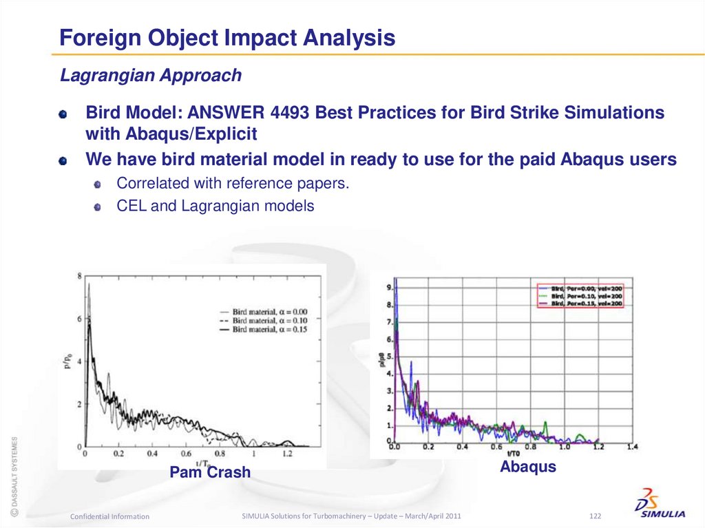
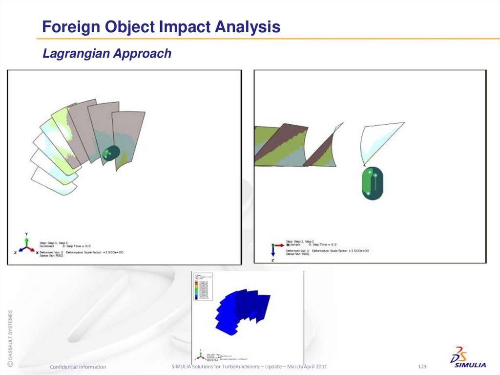
Foreign Object Impact AnalysisLagrangian Approach
Bird Model: ANSWER 4493 Best Practices for Bird Strike Simulations
with Abaqus/Explicit
We have bird material model in ready to use for the paid Abaqus users
Correlated with reference papers.
CEL and Lagrangian models
Pam Crash
Confidential Information
SIMULIA Solutions for Turbomachinery – Update – March/April 2011
Abaqus
122
116. Blade-out
Foreign Object Impact AnalysisLagrangian Approach
Confidential Information
SIMULIA Solutions for Turbomachinery – Update – March/April 2011
123
117. Blade-out
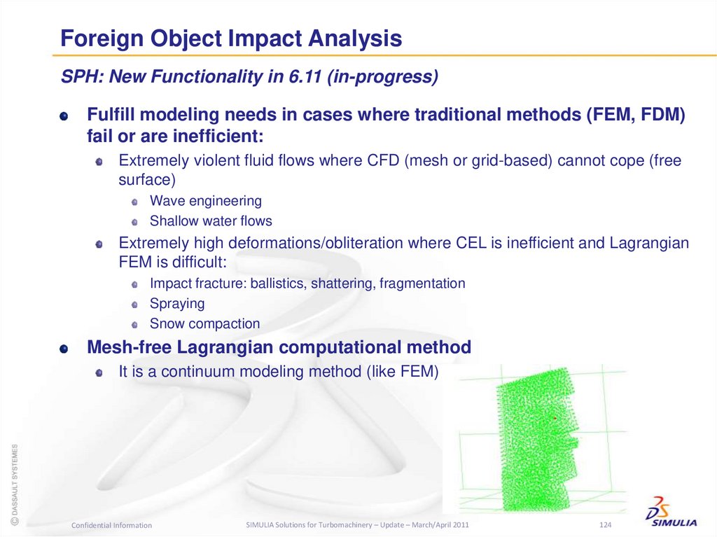
Foreign Object Impact AnalysisSPH: New Functionality in 6.11 (in-progress)
Fulfill modeling needs in cases where traditional methods (FEM, FDM)
fail or are inefficient:
Extremely violent fluid flows where CFD (mesh or grid-based) cannot cope (free
surface)
Wave engineering
Shallow water flows
Extremely high deformations/obliteration where CEL is inefficient and Lagrangian
FEM is difficult:
Impact fracture: ballistics, shattering, fragmentation
Spraying
Snow compaction
Mesh-free Lagrangian computational method
It is a continuum modeling method (like FEM)
Confidential Information
SIMULIA Solutions for Turbomachinery – Update – March/April 2011
124
118. Blade-out
Foreign Object Impact AnalysisSPH: New Functionality in 6.11 (in-progress)
A cylindrical bird strikes an initially straight edge of a rotating turbofan
blade
The blade deforms and the bird disintegrates
Contour plots of pressure shown
4.2 K particles
0:47 mins on a PC
EOS material with tensile
failure
Elasto-plastic blade
Confidential Information
SIMULIA Solutions for Turbomachinery – Update – March/April 2011
125
119. Blade-out
Thank you!Any questions?
youngwon.hahn@3ds.com
jack.cofer@3ds.com
www.simulia.com
SIMULIA Technical
Confidential
Marketing
Information
SIMULIA
SIMULIA
Solutions
Solutions
for for
Turbomachinery
Turbomachinery
– Update
– Update
– March/April
– January 2011
2011
126







 software
 mechanics


