


")


")


")


")


")
")


 software
Similar presentations:


What’s new in InventorCAM 2015
1. What’s new in InventorCAM 2015
InventorCAM 2015What’s new in InventorCAM 2015
www.inventorcam.com
2. General
InventorCAM 2015General
www.inventorcam.com
3. Templates: Default templates for 2.5D Mill operations
• Default templates are set in InventorCAM settings when new operation iscreated these templates are used
• Useful for example to have a default starting Tool
www.inventorcam.com
4. Quick Start settings - Skip “New CAM-part” dialog
• Options in SolidCAM settings to skip the first New CAM-part dialog with default values• Enables the user to start directly adding operations in a new Part
www.inventorcam.com
5. Feed units: mm/rev or mm/min by default
• Define default feed type for new CAM-parts in InventorCAM settingswww.inventorcam.com
6. CAM tree: Advanced sorting of operations
• Possibility to sort operations in CAM-tree by tool number and tool properties(Diameter, Tool Type)
www.inventorcam.com
7. CAM-tree: Show Tool Offset numbers
• Show Tool Offset numbers in CAM-treewww.inventorcam.com
8. Operations: Additional parameters to INFO dialog
• Show Cutting depth information and Additional tool data in Info dialogwww.inventorcam.com
9. Operations: Description of parameters in GUI
• Description of user-defined parameters is now visible inside the operationwww.inventorcam.com
10. Generate G-code per operation
• Generate separate file of G-code per each operationwww.inventorcam.com
11. Use split name as G-code file name
• Use name of Split as name of G-code filewww.inventorcam.com
12. Stock: Take target model dimensions by default
• When Stock definition mode is set to Absolute Coordinates – dimensions of Targetmodel will be taken automatically
www.inventorcam.com
13. High precision of box for CoordSys definition (facetting)
• “ High precision“ for box (facetting) set to ON always during CoordSys definitionwww.inventorcam.com
14. Rotate model to isometric in CoordSys manager
• Rotate model to isometric view when clicking on CoordSys in CoordSys managerwww.inventorcam.com
15. Defaults through Settings for Feed Link, Lead in, Lead out
• Possibility to define defaults through Settings for Feed Link, Lead In and Lead Outwww.inventorcam.com
16. MCO: Faster action definition
• Double click on the item in the „Action on...“ list automatically adds this item tothe Process list.
www.inventorcam.com
17. Machine ID: Change language of VMID
• Possibility to show MachineID editor fields in any language, independent frommain installation language
www.inventorcam.com
18. CoordSys
InventorCAM 2015CoordSys
www.inventorcam.com
19. CoordSys: Always build box around target model
• Create by default CoordSys envelope box around the target• Useful for CoordSys Origin definition
www.inventorcam.com
20. CoordSys: Changes in CoordSys dialog
• Radial movement levels are now on the main dialogue (instead of TAB)• Better noticed by user
www.inventorcam.com
21. CoordSys: Associativity with Inventor Coordinate System
• Support of associativity of a CAM CoordSys, that is built on a Inventor CoordSyswww.inventorcam.com
22. Copying of CoordSys in transformation style: Matrix
• Create copies of existing CoordSys in Matrix stylewww.inventorcam.com
23. Copying of CoordSys in transformation style: Custom Axis
• Create copies of existing CoordSys arounduser-defined axis
www.inventorcam.com
24. Copying of CoordSys in transformation style: Combined transformation
• Combine 2 styles of CoordSys copying• User can use each style of transformation only once
www.inventorcam.com
25. Select all operations of the same CoordSys
• Fast selection of all operations defined in the Coordsys (MAC ) and it‘s positionswww.inventorcam.com
26. Transformation
InventorCAM 2015Transformation
www.inventorcam.com
27. Transform: Matrix without original operation
• Possibility to make Matrix witout original operation toolpath• Useful for postponed transformed operations
www.inventorcam.com
28. Transform: Matrix sorting options
• Additional Sorting options in Matrix transformationwww.inventorcam.com
29. Transform: Marking of sorting types affected by optimization
• If Optimization of operation loops is turned on in *.VMID, the sorting types whichwill be affected by optimization, are marked by green color
www.inventorcam.com
30. Transform: Optimize Matrix Sorting in 4x transformation
• If “optimize Matrix sorting“ is checked – movements between 4th axis positionsare done to minimize tool movements
www.inventorcam.com
31. Transform: Clearance radius for movements between 4th axis positions
• Use Tool Z level from MACx-posN for movements between planes inTransformation around 4x
www.inventorcam.com
32. Transform: Access to transform from operation
• Possibility to open Transform dialog straight from the Operation dialogwww.inventorcam.com
33. Transformation of operations from one CoordSys to another
• Coordsys where operations should be copied to , should contain only 1 position(other positions will be created automatically )
• Useful for Tombstone operations as it enables the simple transfer of an operation
to any Coordinate system, created on any face of the Tombstone.
www.inventorcam.com
34. Tooltable
InventorCAM 2015Tooltable
www.inventorcam.com
35. Tooltable: Changes in STL holders library
• Combine Milling and Turning STL Holders under one machine librarywww.inventorcam.com
36. Tooltable: Update operation feeds/spins according to tooltable
• Possibilitiy to update feeds and spins in operations according to changes in tooltable• Available from tooltable and from CAM-tree
www.inventorcam.com
37. Tooltable: Permanent tool keeps it’s number during import
• If tool is marked as permanent – it will be imported without any change in any fieldwww.inventorcam.com
38. Tooltable: Insert only – add Lead angle
• Option to rotate insert, when working in Insert only mode, by setting Insert Lead anglewww.inventorcam.com
39. Geometry
InventorCAM 2015Geometry
www.inventorcam.com
40. Geometry: Filtering of Pocket Recognition faces by color
• Select only faces of specified color in Pocket Recognition geometrywww.inventorcam.com
41. Geometry: Automatic Curve propagaton with Tangent and Delta-Z
• Creating chain geometries has been made a lot easier - this option enables you to usea combination of Tangent and Delta Z to create Multi level Chains.
www.inventorcam.com
42. Geometry: Selection of faces by color
• Select only faces of specified color in HSS and 5x geometrieswww.inventorcam.com
43. Pocket geometry: Option to add Offset
• Option to add offset to geometry of Pocket operation• Enable user to handle tolerances, without defining new geometry
www.inventorcam.com
44. Slot geometry: Option to add Offset
• Option to add offset to geometry of Slot operation• Enable user to handle tolerances, without defining new geometry
www.inventorcam.com
45. Drill geometry: Modify option
• X and Y shiftings available per hole for Drilling geometrywww.inventorcam.com
46. 2D Geometry: Changes in wrapped geometry definition
• User Interface changes in Wrapped geometry definitionwww.inventorcam.com
47. 2D Geometry: Reverse geometry by F5 button
• Easy way to reverse geometry – press F5 button on keyboardwww.inventorcam.com
48. 2.5D Mill
InventorCAM 20152.5D Mill
www.inventorcam.com
49. Face milling: Vertical ramping option
• New option “Vertical“ for Ramping options in Face milling operationwww.inventorcam.com
50. Face milling: Cutting direction optimization
• For long geometriesthat require one way
face milling – there is
option to skip long noncutting tool moves
www.inventorcam.com
51. Face milling: Shifting from center
• Shift the single cutting pass by applying % of tool diameterwww.inventorcam.com
52. 2.5D Mill: Mark by icon changes of geometry offsets
• If in an operation, modification of geometry was applied – an icon indicating achange occured appears near Geometry button.
www.inventorcam.com
53. Profile: Helical movement improvement
• Different start positions: From top to bottom, From bottom to top• Optional flat circular movement at the bottom of helical cut
www.inventorcam.com
54. Profile: Lead in/out on each pass of Clear offset
• Use lead in/out on each cut of Clear offset strategywww.inventorcam.com
55. Pocket: Variable depth
• Define depth of pocket per chain => possibility to machine pockets with same start levelbut different depths, in same operation
www.inventorcam.com
56. Pocket: Several wall finish passes
• Several finish passes at the same place in Pocket operationwww.inventorcam.com
57. Toolbox
InventorCAM 2015Toolbox
www.inventorcam.com
58. Toolbox: Angled cylinder
• Machining of angled cylinder• Minimizing air cuts
www.inventorcam.com
59. Toolbox: Saw machining
• Special strategy for wood cuttingwww.inventorcam.com
60. Toolbox: Rib face milling
• Cleaning of rib faceswww.inventorcam.com
61. Toolbox: Roll into closed slot
• Constant tool loading, when entering a closed slotwww.inventorcam.com
62. Toolbox: Roll into open slot
• Constant tool loading when entering an open slotwww.inventorcam.com
63. Toolbox: Thin wall machining
• Special strategy for 2.5D thin wall machiningwww.inventorcam.com
64. Automatic Feature Recognition and Machining (AFRM)
InventorCAM 2015Automatic Feature Recognition and Machining (AFRM)
www.inventorcam.com
65. AFRM: Chamfer recognition and machining
• Automatic recognition and machining of edges where it is possible to apply chamferwww.inventorcam.com
66. AFRM: Chamfer recognition and machining
• The Automatic recognition of edges is smart and avoids gouging the wallswww.inventorcam.com
67. Automatic Hole Recognition and Machining (AHRM)
InventorCAM 2015Automatic Hole Recognition and Machining (AHRM)
www.inventorcam.com
68.
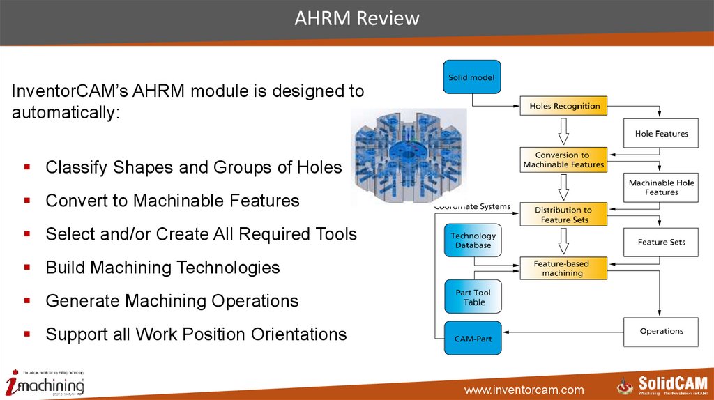
AHRM ReviewInventorCAM’s AHRM module is designed to
automatically:
Classify Shapes and Groups of Holes
Convert to Machinable Features
Select and/or Create All Required Tools
Build Machining Technologies
Generate Machining Operations
Support all Work Position Orientations
www.inventorcam.com
69.
AHRM review – Process stepsStep 1: Recognize Holes
(Shapes & Groups)
Step 2: Convert Holes to
Machinable Segments
Step 3: Distribute
Machinable Segments
to Feature Sets
Step 4: Choose
Technological Solution
for Machinable
Segments
Step 5: Generate all
Machining Operations
www.inventorcam.com
70.
AHRM review - Step 1: Recognize HolesStep 1: Recognize Holes
(Shapes & Groups)
www.inventorcam.com
71.
AHRM review - Step 2: Machinable segmentsStep 2: Convert Holes to
Machinable Segments
The Machinable Hole Feature
consists of one or more
Machinable Hole Feature
segments that can be machined
in one operation with the same
tool.
www.inventorcam.com
72.
AHRM review - Step 3: Feature SetsStep 3: Distribute
Machinable segments
to Feature sets
Feature Set is a
number of Machinable
segments that will be
machined within the
same setup using one
Coordinate System.
www.inventorcam.com
73.
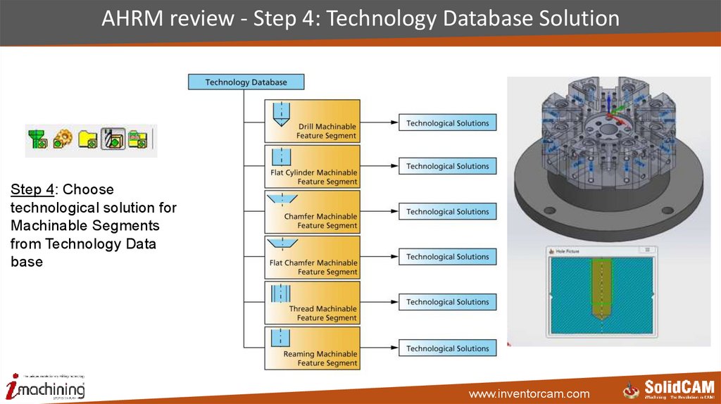
AHRM review - Step 4: Technology Database SolutionStep 4: Choose
technological solution for
Machinable Segments
from Technology Data
base
www.inventorcam.com
74.
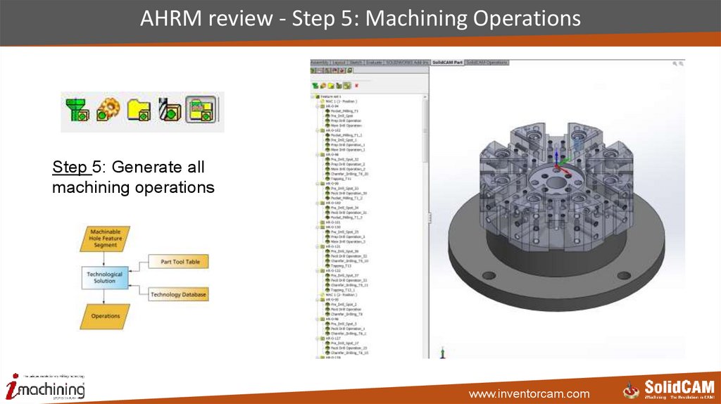
AHRM review - Step 5: Machining OperationsStep 5: Generate all
machining operations
www.inventorcam.com
75.
AHRM New: Limitless number of DataBase configurationsThe user can:
• Define as many DataBases as he wants
• Select any of them for the process
• Edit the “Part DataBase ” Independently
• Save active DataBase As a NEW one
www.inventorcam.com
76.
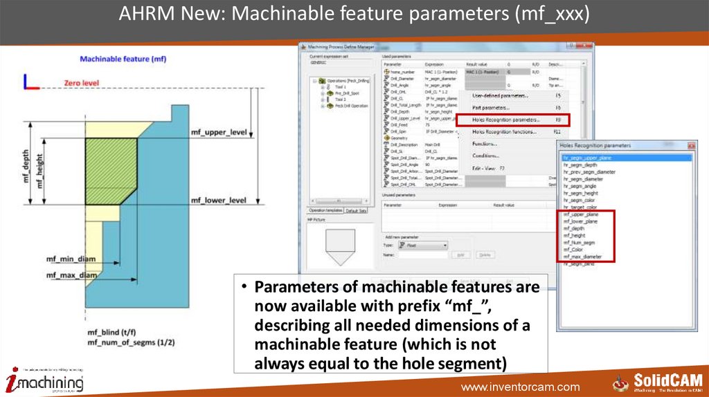
AHRM New: Machinable feature parameters (mf_xxx)• Parameters of machinable features are
now available with prefix “mf_”,
describing all needed dimensions of a
machinable feature (which is not
always equal to the hole segment)
www.inventorcam.com
77. AHRM New: Conditional Logic Support
• Apply different values to parameters, according to user-defined condition in theMachining Process of the AHRM (e.g. Enables Spot drills to be chosen according to
hole size)
www.inventorcam.com
78. iMachining 2D & 3D
InventorCAM2015iMachining 2D & 3D
www.inventorcam.com
79. Parallel calculation in iMachining
• Speeding up iMachining calculation by using multi cores & multi threading forparallel calculation
www.inventorcam.com
80. iDatabase Material: Machinability factor
• Increase/Decrease Cutting Conditions, based on Machinability of specific materialwww.inventorcam.com
81. iMachining: Constant chip thickness control for arcs
• Controls the feed correction for arcs• Value of 0 means no feed rate correction, resulting in faster cutting and higher tool wear
• Value of 100 means complete correction, slower cutting but less tool wear
www.inventorcam.com
82. iMachining 3D: Constant Step up
• iMachining 3D option: Constant Set up (as alternative to Scallop)www.inventorcam.com
83. iMachining 3D: Prismatic parts machining technology
• iMachining 3D technology for Prismatic Part Machining with automatic scallopcalculation
www.inventorcam.com
84. iMachining 3D: Floor offset
• Enables you to define a Floor offset that is separate from the Wall offsetwww.inventorcam.com
85. Show Cutting angle in simulation of iMachining
• Showing the cutting angle in iMachining simulationwww.inventorcam.com
86. 3D Milling
InventorCAM 20153D Milling
www.inventorcam.com
87. 3D Milling: Reposition options
2 options of tool reposition:• By Rapid move through clearance plane
• By Feed move through saftey distance from the surface
www.inventorcam.com
88. HSR/HSM
InventorCAM 2015HSR/HSM
www.inventorcam.com
89. HSR/HSM: Major Speeding up of updated stock calculation
• Choose in Settings option of speeding up Updated stock calculation, if all previousoperations are HSR/HSM
• Saving on average 40% in updated stock calculation time
www.inventorcam.com
90. HSR/HSM: Selection of non-calculated operations for updated stock
• Even if previous operations are not calculated , it‘s possibe to select them forfurther updated stock calculation in HSR Rest Roughing
www.inventorcam.com
91. HSR/HSM: Use updated Stock for linking
• Links the passes using dynamic stock(updated stock), instead of static stock (theinitial stock), resulting in a very efficient toolpath
www.inventorcam.com
92. HSM: Ramping options added to Constant-Z machining
• Ramping options, added to HSM Constant Z machining, similar to HSR operations, areuseful to increase tool life, when finishing is done immediately after roughing
www.inventorcam.com
93. HSR/HSM: Link by area added to HM Roughing
• Pockets are machined independently, but within a pocket, strict Z level ordering isenforced
www.inventorcam.com
94. Sim 5X Milling & HSS
InventorCAM 2015Sim 5X Milling & HSS
www.inventorcam.com
95. Feed Control
New Feed Control tab added.Feed Control enables the user to reduce/
increase cutting feed inside & outside defined
volumes.
www.inventorcam.com
96. Toolpath parameters: Synchronize points
Surface quality tab: New option of Synchronize points added.Option is available when the Distance check box is ON.
The Synchronize points option enables
you to equalize the spacing and
number of points on all contours, thus
getting better surface quality
Without Synchronization
With Synchronization
www.inventorcam.com
97. Sim 5x: Advanced mode button
• Only most used options are open in the standard interface, making it easier for customers• Advanced button opens additional control options, needed by advanced users
www.inventorcam.com
98. Sim5X - Tool axis control: Always closest to surface
In Tool axis direction/Tilted throughlines: New option of Always closest to
surface is added in the Use tilt through.
This option enables you to tilt the tool
as defined in the Tilt lines section,
maintaining always the tool at closest
distance to the surface, avoiding
sudden tilting
This option maintains the tilt by using
the tilt lines that are at the closest
distance to the surface.
www.inventorcam.com
99. Sim5X - Tool axis control: Tilted relative to contact point
In Tool axis direction: New option ofTilted relative to contact point is added.
This option is similar to “Tilted Relative
to Cutting Direction”, however in this
option instead of cutting direction, the
tool tilting will be relative to the contact
point of the tool with the surface.
www.inventorcam.com
100. New operation: Multiaxis Roughing
New Multiaxis Roughing operation is added for Roughing of parts, that need multiplesetup if done in 3X.
www.inventorcam.com
101. New operation: MultiAxis Roughing
This operation creates a multiaxis tool paththat can be used to rough out pocket shaped
geometries in full 5 Axis.
The user has to specify the floor, wall and
ceiling surfaces and the system automatically
creates the roughing tool path.
Adaptive roughing feature also available.
www.inventorcam.com
102. Contour 5x machining: Enforce cutting direction
• Direction is set according to direction of machining, ignoring the selected chaindirection
www.inventorcam.com
103. Contour 5x Machining: Tilt away from line
• Tilt away from line defines the side tilt of the tool relative to the contourwww.inventorcam.com
104. Multiblade Machining: Machine angle limits – Min & Max
Multiblade Machining: Machine angle limits – Min & Max• Machine angle limit is now controlled by two parameters: minimum and maximum
angle, rather than by only one limit angle in older versions, giving much better control
of angles in CNC machines that have less swivel
www.inventorcam.com
105. Multiblade Machining: Entry & Exit Safety distance
Multiblade Machining: Entry & Exit Safety distance• Safety distance is divided into two fields: Entry & Exit safety distance, providing better
control
www.inventorcam.com
106. Multiblade Machining: Additional Clearance type - Conical
• A new Tool Clearance type, Conical, is added to enable cutting more material andworking deeper, while avoiding gouging
www.inventorcam.com
107. Multiblade Machining: Levels section
Levels page: New Levels section is added to enable entry and exit safety distance.www.inventorcam.com
108. Multiblade Machining: Tool Axis Control Limits
Tool axis control page: Limits section has enhancements.www.inventorcam.com
109. Multiblade Machining: Plunge arc for link between slices or layers
• Option to use a plunge arc, while performing link between slices or layers, in order toprovide gradual entry into the material
• Enables you to specify the diameter of the approach & retreat arc, using the ratio of the
Arc diameter to the Tool diameter
www.inventorcam.com
110. Multiblade Machining: GUI Improvements
Tool path parameters page/Technology/ Options of Rest material, First slice, and Areaare available only when the Advanced check box is selected.
www.inventorcam.com
111. Multiblade Machining: GUI Improvements
Roughing and More is renamed as Stock and Transformation.www.inventorcam.com
112. Port Machining: Additional Clearance type - Conical
• A new Tool Clearance type, Conical, is added to enable cutting more material andworking deeper, while avoiding gouging
www.inventorcam.com
113. Port Machining: Tool axis control page
Tool axis control page added in order to provide smoother tool tilting during cuttingwww.inventorcam.com
114. Port Machining: Tool Axis Control - Minimize Tilting
Tool axis control: Minimize tilting isadded.
This option improves tool tilting by
minimizing angle changes and keeping
machine tilt motions to minimum.
www.inventorcam.com
115. SWARF Machining: Surface normal defines machining side
• Side of machining is determined according to the surface normal, simplifying thedetermination of the machining side when machining multiple surfaces
www.inventorcam.com
116. SWARF Machining: New Avoid gouge strategy and new Layout for gouge page
• New Avoid Gouge strategy, Avoid by Retracting, enables the user to avoidobstacles by retracting the tool.
• New simplified layout for gouge page.
www.inventorcam.com
117. SWARF Machining: Feed control
• More flexible control over cutting and retract speeds• Possibility to replace Rapid movements by G1 moves
www.inventorcam.com
118. SWARF Machining: Adding extensions to toolpath
• New option to add extensions to the tool path, to avoid direct entry into the material,thereby increasing tool life
www.inventorcam.com
119. SWARF Machining: Degouging strategy
Degouge option• New options to avoid gouges with drive surface
www.inventorcam.com
120. SWARF Machining: Rotate & Translate
SWARF Machining: Rotate & Translate• Rotate & Translate option is available for SWARF operation also
www.inventorcam.com
121. SWARF/MultiBlade/Port/MultiAxis Roughing: Custom triangulation
Provide more control over surfacetriangulation
Custom triangulation check box = OFF,
SolidCAM uses the native CAD
triangulation method.
Custom triangulation check box = ON,
5-Axis triangulation method is used to
define the Triangulation tolerance and
Max. edge length.
www.inventorcam.com
122. Multiaxis Drilling: retract tool along tool axis
• Avoid collisions by preventing sudden tool „jumps“www.inventorcam.com
123. Multiaxis Drilling: Use Cycle option
The Multiaxis Drilling Technologypage has a new option: Use cycle.
When this check box is ON, the
generated G-code uses canned drill
cycles, if CNC machine enables it.
If this check box is OFF, the output
is in the form of linear movements.
www.inventorcam.com
124. Convert HSM to Sim 5-Axis Milling: Autotilt
New Technology of Autotilt is added.This option enables the conversion of a
3-axis input tool path into a full automatic
collision-checked 5-axis tool path.
The main aim is to take the 3-axis tool path
and use it with a much shorter tool.
The automatic tilting now does compensate
the holder with the geometry and tilts it
away.
www.inventorcam.com
125. Convert HSM to Sim 5-Axis Milling: Autotilt
Tool axis control page has new options when Autotilt is selected as Technology.www.inventorcam.com
126. Convert HSM to Sim 5-Axis Milling: Autotilt - Workpiece Clearance
Source operation page has the newoption of Workpiece clearance.
The Workpiece clearance option
enables you to set a value by which the
tool clears the workpiece when moving
between two positions.
Note: This option is available only with
the Autotilt technology.
www.inventorcam.com
127. Roughing and More Page: Trim only full contours
Stock definition: New option of Trim only full contours is added.Enables you to keep the cuts that are partially within the stock and remove the cuts
which are completely outside the stock - enabling much smoother cuts and less jumps.
www.inventorcam.com
128. GUI Changes - Geometry Page
2D Boundary curves content is placed inside Geometry page.www.inventorcam.com
129. GUI Changes - Levels Page
Parameters divided into two tabs: Regular (most used) and Advanced.www.inventorcam.com
130. GUI Changes - Toolpath parameters Page
New Modify tab is added.Round corners, Extend/Trim, and Angle
range moved to this page from
Geometry page since they are related to
toolpath.
Modify tab is available only when the
Advanced check box is ON.
www.inventorcam.com
131. Gouge check Page: Smooth Retracts
Strategy: Retract along tool axis/ Advanced:New option of Smooth retracts is added.
The Smooth retracts check box enables
you to smooth the transition from the
collision free area to the tool retraction
area by avoiding sudden axis jumps.
The Smooth distance field determines
the start distance of the smoothing to
the collision area.
www.inventorcam.com
132. Gouge check Page: Renaming of strategies
The Gouge check strategies are logically namedwww.inventorcam.com
133. Gouge check Clearance data Page
Remaining collisions section is updated – one option removed.www.inventorcam.com
134. Turning
InventorCAM 2015Turning
www.inventorcam.com
135. Turning: Torochoidal Turning operation
• iMachining-style torochoidal moves of round grooving tool in turningwww.inventorcam.com
136. Turning: Use all milling tools in turning drilling
• Possibility to use Milling tools in Turning Drilling operationwww.inventorcam.com
137. Turning: Offset types in face turning
@turning ==> work_type:rough semi_finish:false finish:false..> label:5002 start_line:10 end_line:12
..> process_type:face turning_mode:external
..> is_line:false num_points:0
..> rough_offset_x:0.000 rough_offset_z:0.200
..> semi_offset_x:0.000 semi_offset_z:0.000
..> first_pos_x:26.600 first_pos_z:0.000
..> last_pos_x:5.600 last_pos_z:0.000
..> down_step:1.000 safety:2.000
..> retreat_distance:0.200
• Output offset value in Face turning cycle
www.inventorcam.com
138. Turning: Negative X output
• Possibility to get (-X) cutting toolpath with start/end points in (+X)www.inventorcam.com
139. Turning: Non-descending motion on face surfaces also
• Option to avoid penetration to slots on face surfaces alsowww.inventorcam.com
140. Turning: Auto Lead in/out cancelled
IC2014IC2015
• In previous versions, an additional movement before Lead in/out was added
automatically. In this version they are not added; user defines lead-in and lead-out
www.inventorcam.com
141. Turning: Lead in/out Used in rough turning also
IC2014IC2015
without Lead in
with Lead in
IC2015
without Lead in
• In previous versions, we had only an automatic lead in/out for roughing
• Now the automatic lead in/out is cancelled and manual lead in/out, if defined,will
be applied to Rough toolpath also
www.inventorcam.com
142. Turning: Split long lines of turning toolpath
• Split long lines of turning toolpath to short lines, according to the distance definedwww.inventorcam.com
143. Mill-Turn
InventorCAM 2015Mill-Turn
www.inventorcam.com
144. Machine ID: Machine orientation
Z- Blue, X- Red• World CoordSys is always with Z vertically UP
• Machine orientation (vertical, horizontal) is defined in World CoordSys
www.inventorcam.com
145. Turret: New style of station creation in VMID
• Easy way to create multiple stations in VMIDwww.inventorcam.com
146. MCO: Calculate all related operations when MCO changes
• Automatic calculation of changed MCO‘s related operationswww.inventorcam.com
147. MCO: Move Part by turret or any other device
• Possibility to move the CAM-part from Table to Table by turret or any other devicewww.inventorcam.com
148. Tooltable: new mounting interface
• New tool mounting interface – based on station and device CoordSys• Shown as it actually looks in CNC Machine
www.inventorcam.com
149. Tooltable: Show station name
• Show station name in the List of stations in Tooltablewww.inventorcam.com
150. Update material boundary (for mill-turn)
• Take into account HSR/HSM operations when updating stock for further turningoperations
www.inventorcam.com
151. Definition of Cross Control
• By default – cross control isalways turned on
• *.VMID allows to cancel Cross
Control (access to devices from
opposite channel), if it is not
supported by the machine.
Cross control: yes
Cross control:no
All devices are
available in MCO
Devices in MCO are
filtered by channels
www.inventorcam.com
152. Channels definition in VMID
• Custom channels definition• Definition of channels by submachines, not turrets
• Enables synchronisation
process between tables (Swiss
Type lathes)
www.inventorcam.com
153. Full support of Mazak Mill Turn machines
Opposite spindle
Rotary turret
Simultaneous 5 axes
Balanced turning
Part transfer
Additional devices
www.inventorcam.com
154. Full support of Fanuc Mill Turn machines
• Opposite spindle• Rotary turret with milling
functionality
• Simultaneous 5 axes
• Balanced turning
• Part transfer
• Additional devices
www.inventorcam.com
155. Support of machines with combined turrets
Opposite spindle
Rotary turret as B-axis
Linear turrets
Simultaneous 5 axes
Synchronization
Part transfer
Combined turrets
www.inventorcam.com
156. Support of Multi-station Combined-turrets Mill-Turn machines
Quicktech Ultimate I42• Two spindles, Each turret is a combined turret (Rotary type and Linear type)
• Channel synchronization by tables
www.inventorcam.com
157. Support of Willemin-style Mill-Turn machines
Willemin 508 MTCutting Video 1
Cutting Video2
• Willemin-style: Two spindles, B-axis, Additional devices (Clamps and tail Stock)
• Additional devices support by MCO, with full machine simulation
www.inventorcam.com
158. Support of Chiron-style Mill-Turn machines
Chiron FZ 12 MT• Chiron-style: Main spindle, Rotary Turret, B-axis, Tilting of back spindle
• Full support of MCO operations with full machine simulation
• Working with Synchronization (Multi-Channel)
www.inventorcam.com
159. Support of Index-style Mill-Turn machines
Index R200• Index-style: Two spindles, Each turret is a combined turret (B-axis type and Linear type)
• Full support of MCO operations, with full machine simulation
• Programming by Channels (not by Turrets)
www.inventorcam.com
160. Simulation
InventorCAM2015Simulation
www.inventorcam.com
161. Simulation: Show STL holders in simulation
• Show STL holders in simulation and in gouge checkingwww.inventorcam.com
162. Simulation: Show current CoordSys in SolidVerify simulation
• Show current CoordSys in SolidVerify simulation• Useful for Shop Floor Editor, where SolidCAM runs standalone.
www.inventorcam.com
163. Tool Libraries integrations
InventorCAM 2015Tool Libraries integrations
www.inventorcam.com
164.
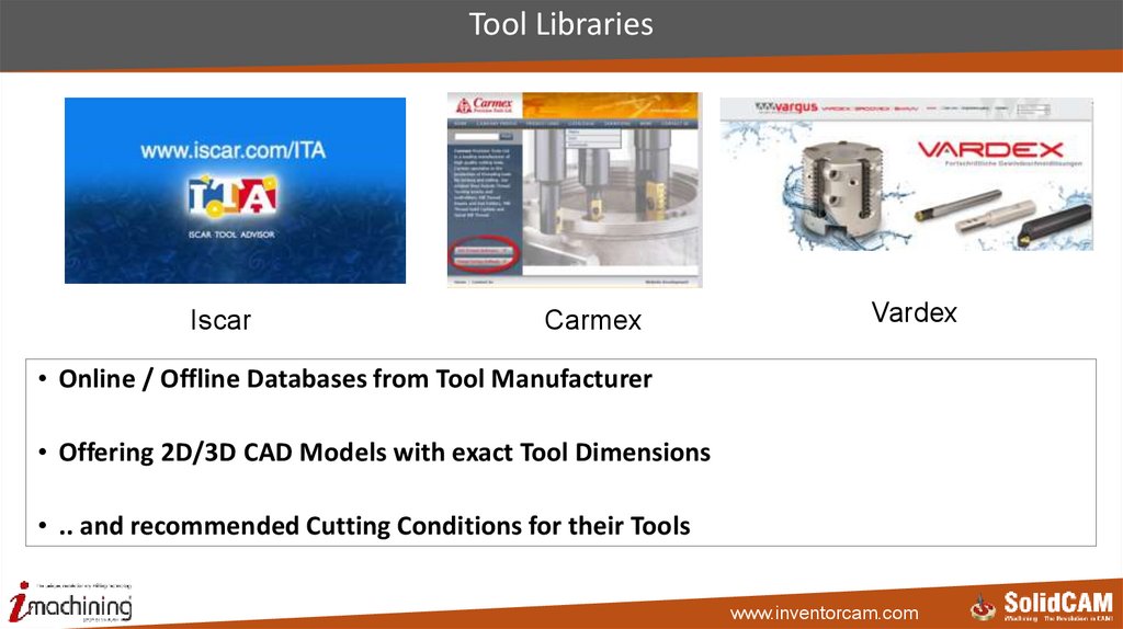
Tool LibrariesIscar
Carmex
Vardex
• Online / Offline Databases from Tool Manufacturer
• Offering 2D/3D CAD Models with exact Tool Dimensions
• .. and recommended Cutting Conditions for their Tools
www.inventorcam.com
165. ISCAR Tool Advisor (ITA)
• Online Catalog with assistance to guide users to the best ISCAR Toolswww.inventorcam.com
166. Integration with ISCAR Tool Advisor (ITA)
http://www.iscar.com/ita/MainPage.aspx• At the Import Option of the Tool Table, select ISCAR Tool Advisor to launch it
www.inventorcam.com
167. Carmex
http://www.carmex.com• Carmex is specialized in the Production of Threading Tools for Turning and Milling
www.inventorcam.com
168. Integration with Carmex Tool Library
( Carmex software should be installed )• Integration at the Tool Type Thread Mill in the Table of Pitch / Standard
• Select Carmex from the List - Carmex Tool Recommendation Software starts
www.inventorcam.com
169. Vardex
http://www.vargus.de/• Vardex is a Product Line from Vargus for Threading Tools
www.inventorcam.com
170. Integration with Vardex Tool Library
( Vardex software should be installed )• Integration at the Tool Type Thread Mill in the Table of Pitch / Standard
• Select Vardex from the List - The Vardex TM Assistant starts
www.inventorcam.com
171. Tool Management Softwares Integration
InventorCAM 2015Tool Management Softwares Integration
www.inventorcam.com
172. Tool Data Management Softwares
TDMWinTool
• Software to manage the overall information of Tools
www.inventorcam.com
173.
Tool Data Management (TDM) SoftwareCutting Conditions
Production Information
2D / 3D CAD Model
Tool Presetting
www.inventorcam.com
174.
Workflow using TDM SoftwareCollect Data
e.g. downloaded 2D/3D
CAD Models
Create a Tool with a combination
of Data
Build a Tool as a combination of
different CAD Models and Information
Use in InventorCAM
Import Tool Option
Tool with Holder imported
from TDM Software
www.inventorcam.com
175. TDM Version 4.6
http://youtu.be/A3a-jyhMmUYwww.inventorcam.com
176. Management of Tools and Manufacturing Data in TDM
Collect componentsAssemble it
Export to CAM
• Users collect the models form online Recourses and build the Assembly of the whole
Tool inside TDM
• TDM generates automatically ready to use Data for the InventorCAM Tool Table
www.inventorcam.com
177. Integration with TDM
(TDM should be installed at the Client / Server)Tool Import filtering dialog
• At the InventorCAM Import Option of Tool table, select TDM – tool import filtering
dialog opens
www.inventorcam.com
178. WinTool Professional 2012
The Framework for higher EfficiencyManagement of Tools and Manufacturing Data
Tool Catalogs
WinTool
Setup + Machining
Documents + Planning
Integration and Simplification
Job Lists + Presetting
Storage Systems
© WinTool AG – www.wintool.com
For more nformation
click to the Logo
• WinTool - Software for Tool Data Management
www.inventorcam.com
Assembly + Logistics
1
179. Management of Tools and Manufacturing Data
Collect componentsAssemble it
Export to CAM
• Users collect the Models form Online Recourses and build the Assembly of the whole Tool
inside WinTool
• WinTool generates ready to use Tool Data to import to InventorCAM ToolTable
www.inventorcam.com
180. Integration with WinTool
(WinTool Professional should be installed and started)• At the InventorCAM Import Option of the Tool table, select Wintool - Tool Export Dialog
opens
www.inventorcam.com