


")


")


 mechanics
Similar presentations:

Rotordynamics
1.
Rotordynamics withANSYS Mechanical
Solutions
ANSYS, Inc. Proprietary
© 2009 ANSYS, Inc. All rights reserved.
1-1
April 30, 2009
Inventory #002764
2.
Rotordynamics with ANSYS Mechanical SolutionsTraining Manual
Inventory Number: 002764
1st Edition
ANSYS Release: 12.0
Published Date: April 30, 2009
Registered Trademarks:
ANSYS® is a registered trademark of SAS IP Inc.
All other product names mentioned in this manual are trademarks or registered trademarks of their respective
manufacturers.
Disclaimer Notice:
This document has been reviewed and approved in accordance with the ANSYS, Inc. Documentation Review and
Approval Procedures. “This ANSYS Inc. software product (the Program) and program documentation
(Documentation) are furnished by ANSYS, Inc. under an ANSYS Software License Agreement that contains
provisions concerning non-disclosure, copying, length and nature of use, warranties, disclaimers and remedies,
and other provisions. The Program and Documentation may be used or copied only in accordance with the
terms of that License Agreement.”
Copyright © 2009 SAS IP, Inc.
Proprietary data. Unauthorized use, distribution, or duplication is prohibited.
All Rights Reserved.
ANSYS, Inc. Proprietary
© 2009 ANSYS, Inc. All rights reserved.
1-2
April 30, 2009
Inventory #002764
3. Agenda
1.2.
3.
4.
5.
6.
7.
8.
9.
10.
11.
Training Manual
Why / what is Rotordynamics
Equations for rotating structures
Rotating and stationary reference frame
Elements for Rotordynamics
Commands for Rotordynamics
Campbell diagram - Multi-spool rotors
Backward / forward whirl & orbit plots
Forced response
Instability
Rotordynamics analysis guide
Examples
ANSYS, Inc. Proprietary
© 2009 ANSYS, Inc. All rights reserved.
1-3
April 30, 2009
Inventory #002764
4. Rotordynamics - why / what is rotordynamics ?
Training Manual• High speed machinery such as Turbine
Engine Rotors, Computer Disk Drives, etc.
• Very small rotor-stator clearances
• Flexible bearing supports – rotor instability
Finding critical speeds
Unbalance response calculation
Response to Base Excitation
Rotor whirl and system stability
predictions
• Transient start-up and stop
• Model gyroscopic moments generated by
rotating parts.
• Account for bearing flexibility (oil film bearings)
• Model rotor imbalance and other excitation
forces (synchronous and asynchronous
excitation).
ANSYS, Inc. Proprietary
© 2009 ANSYS, Inc. All rights reserved.
1-4
April 30, 2009
Inventory #002764
5. Rotordynamics features
Training Manual• Pre-processing:
–
–
–
–
–
–
Appropriate element formulation for all geometries
Gyroscopic moments generated by rotating parts
Bearings
Rotor imbalance and other excitation forces
Rotational velocities
Structural damping
• Solution:
– Complex eigensolver for modal analysis
– Harmonic analysis
– Transient analysis
ANSYS, Inc. Proprietary
© 2009 ANSYS, Inc. All rights reserved.
1-5
April 30, 2009
Inventory #002764
6. Rotordynamics features
Training Manual• Post-processing
–
–
–
–
Campbell diagrams
Mode animation
Orbit plots
Transient plots and animations
• User’s guide
• Advanced features:
– Component Mode Synthesis for static parts
ANSYS, Inc. Proprietary
© 2009 ANSYS, Inc. All rights reserved.
1-6
April 30, 2009
Inventory #002764
7. Rotordynamics - theory
ANSYS, Inc. Proprietary© 2009 ANSYS, Inc. All rights reserved.
Training Manual
1-7
April 30, 2009
Inventory #002764
8. Rotordynamics - theory
Training Manual• In a stationary reference frame, we are solving
the following equation:
M u C G u K B u f
• M, C & K are the standard mass, damping and
stiffness matrices
• G & B represent respectively the gyroscopic and
the rotating damping effect
ANSYS, Inc. Proprietary
© 2009 ANSYS, Inc. All rights reserved.
1-8
April 30, 2009
Inventory #002764
9.
Rotordynamics - theoryTraining Manual
Dynamic equation in rotating reference frame
M { u r } ( C [Ccor ]){u r } ( K [K spin ]){u r } F
Coriolis matrix in dynamic analyses:
T
[Ccor ] 2 dv
0
z
y
0
x
x
0
z
y
By extension, the Coriolis force in a static analysis:
{f c } [C cor ]{u r }
ANSYS, Inc. Proprietary
© 2009 ANSYS, Inc. All rights reserved.
1-9
April 30, 2009
Inventory #002764
10.
Rotordynamics – theoryTraining Manual
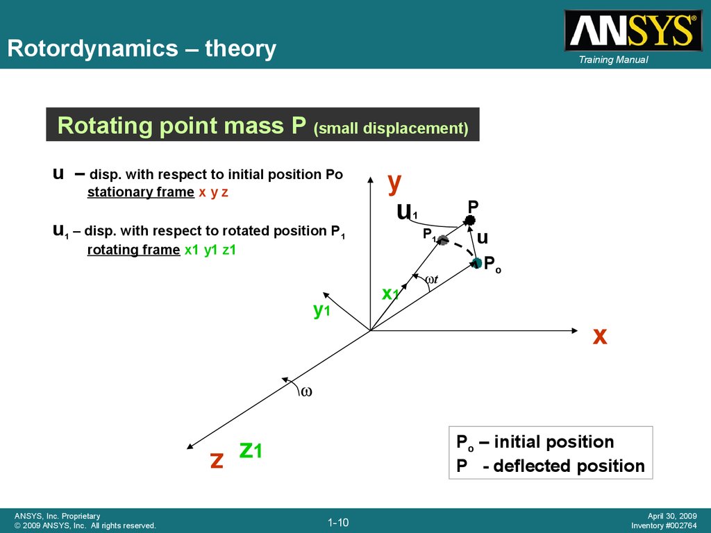
Rotating point mass P (small displacement)
u – disp. with respect to initial position Po
stationary frame x y z
u1 – disp. with respect to rotated position P1
y
u
P1
rotating frame x1 y1 z1
y1
P
1
x1
t
u
Po
x
z
ANSYS, Inc. Proprietary
© 2009 ANSYS, Inc. All rights reserved.
Po – initial position
P - deflected position
z1
1-10
April 30, 2009
Inventory #002764
11.
Rotordynamics - theoryTraining Manual
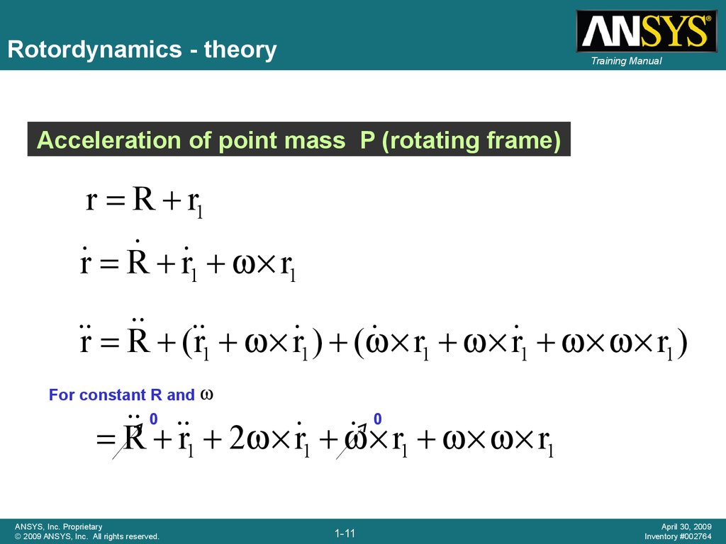
Acceleration of point mass P (rotating frame)
r R r1
r R r 1 r1
( r r ) (
r R
r1 r 1 r1 )
1
1
For constant R and
0
0
r 2 r
r1 r1
R
1
1
ANSYS, Inc. Proprietary
© 2009 ANSYS, Inc. All rights reserved.
1-11
April 30, 2009
Inventory #002764
12.
Rotordynamics - theoryTraining Manual
Acceleration of point mass due to deflection Po – P
(small displacement - rotating frame)
r r0 r r r0 u r1 r10 r1 r10 u1
Acceleration vector
u u
1
2 u 1
u1
Coriolis
ANSYS, Inc. Proprietary
© 2009 ANSYS, Inc. All rights reserved.
spin softening
1-12
r10
centrifugal
April 30, 2009
Inventory #002764
13. Rotordynamics - reference frames
Training Manual• Rotordynamics simulation can be performed in two different
reference frames:
– Stationary reference frame:
• Applies to a rotating structure (rotor) along with a stationary
support structure
• Rotating part of the structure to be modeled must be axisymmetric
– Rotating reference frame:
• The structure has no stationary parts and the entire structure is
rotating
• Consider only the Coriolis force
ANSYS, Inc. Proprietary
© 2009 ANSYS, Inc. All rights reserved.
1-13
April 30, 2009
Inventory #002764
14.
Rotordynamics - reference framesStationary Reference Frame
Training Manual
Rotating Reference Frame
Not applicable in static analysis
Applicable in static analysis
Can generate Campbell plots for
computing rotor critical speeds.
Campbell plots are not applicable for
computing rotor critical speeds.
Structure must be axisymmetric
about spin axis.
Structure need not be axisymmetric
about spin axis.
Rotating structure can be part of
a stationary structure.
Rotating structure must be the only
part of an analysis model (ex: gas
turbine engine rotor).
Supports more than one rotating
structure spinning at different
rotational speeds about different
axes of rotation (ex: a multi-spool
gas turbine engine).
Supports only a single rotating
structure (ex: a single-spool gas
turbine engine).
Our focus in this presentation
ANSYS, Inc. Proprietary
© 2009 ANSYS, Inc. All rights reserved.
1-14
April 30, 2009
Inventory #002764
15.
Rotordynamics - ANSYS elementsTraining Manual
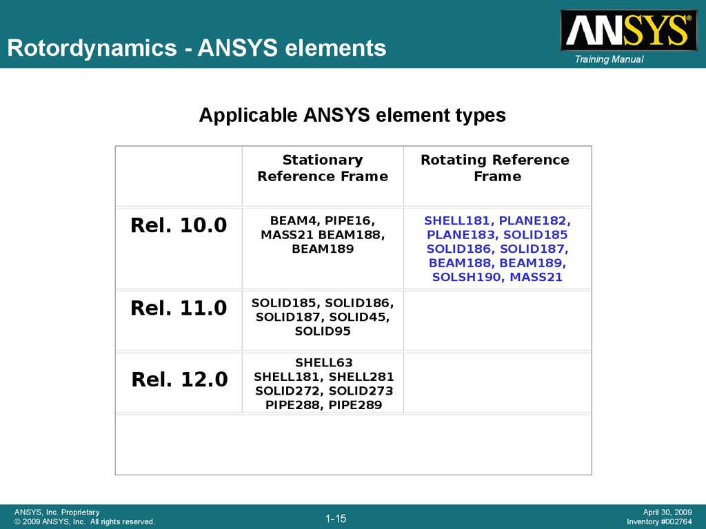
Applicable ANSYS element types
Stationary
Reference Frame
Rotating Reference
Frame
Rel. 10.0
BEAM4, PIPE16,
MASS21 BEAM188,
BEAM189
SHELL181, PLANE182,
PLANE183, SOLID185
SOLID186, SOLID187,
BEAM188, BEAM189,
SOLSH190, MASS21
Rel. 11.0
SOLID185, SOLID186,
SOLID187, SOLID45,
SOLID95
Rel. 12.0
ANSYS, Inc. Proprietary
© 2009 ANSYS, Inc. All rights reserved.
SHELL63
SHELL181, SHELL281
SOLID272, SOLID273
PIPE288, PIPE289
1-15
April 30, 2009
Inventory #002764
16. Rotating damping
Training Manual• Considered if the rotating
structure has:
• structural damping (MP,
DAMP or BETAD)
• or a localized rotating
viscous damper (bearing)
• The damping forces can induce
unstable vibrations.
• The rotating damping effect is
activated along with the Coriolis
effect (CORIOLIS command).
ANSYS, Inc. Proprietary
© 2009 ANSYS, Inc. All rights reserved.
1-16
Damper
COMBI214
Beam
BEAM4, PIPE16
BEAM188, BEAM189
Solid
SOLID45, SOLID95
SOLID185, SOLID186,
SOLID187
SOLID272, SOLID273
(new in V 12.0 )
General
axisymmetric
Elements supporting rotating damping
April 30, 2009
Inventory #002764
17. General axisymmetric element
In v12.0, the new SOLID272(4nodes) and SOLID273
(8nodes) generalized
axisymmetric elements:
• are computationally efficient
when compared to 3D solid
Training Manual
Example of mesh for SOLID272
element with 3 circumferential
nodes.
Only (I1 J1 K1 L1) are input while
all others nodes are
automatically generated.
• support 3D non axisymmetric
loading
ANSYS, Inc. Proprietary
© 2009 ANSYS, Inc. All rights reserved.
1-17
April 30, 2009
Inventory #002764
18. Generalized axisymmetric element
• Allow a very fast setup ofaxisymmetric 3D parts:
• Slice an axisymmetric 3D CAD
geometry to get planar model
• Mesh with 272/273 elements
• No need to calculate equivalent
beam sections
• Can be combined with full 3D
models, including contact
Training Manual
2D axisymmetric mesh
3D representation
• Support Gyroscopic effect in
the stationary reference
frame
3D results (not necessarily axisymmetric)
ANSYS, Inc. Proprietary
© 2009 ANSYS, Inc. All rights reserved.
1-18
April 30, 2009
Inventory #002764
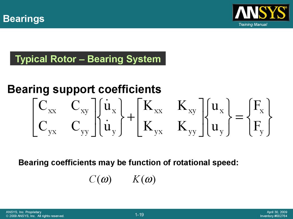
19.
BearingsTraining Manual
Typical Rotor – Bearing System
Bearing support coefficients
C xx
C
yx
C xy u x K xx
C yy u y K yx
K xy u x Fx
K yy u y Fy
Bearing coefficients may be function of rotational speed:
C ( )
ANSYS, Inc. Proprietary
© 2009 ANSYS, Inc. All rights reserved.
K ( )
1-19
April 30, 2009
Inventory #002764
20. Bearings
Training Manual• 2D spring/damper with cross-coupling terms:
– Real constants are stiffness and damping
coefficients and can vary with spin velocity w
• Bearing element choice depends on:
– Shape (1D, 2D, 3D)
– Cross terms
– Nonlinearities
ANSYS, Inc. Proprietary
© 2009 ANSYS, Inc. All rights reserved.
Description
Stiffness and Damping
cross terms
Nonlinear stiffness
and damping
characteristics
COMBIN14
Uniaxial
spring/damper
No
No
COMBI214
2-D spring/damper
Unsymmetric
Function of the
rotational velocity
MATRIX27
General stiffness or
damping matrix
Unsymmetric
No
MPC184
Multipoint constraint
element
Symmetric for linear
characteristics - None for
nonlinear characteristics
Function of the
displacement
1-20
April 30, 2009
Inventory #002764
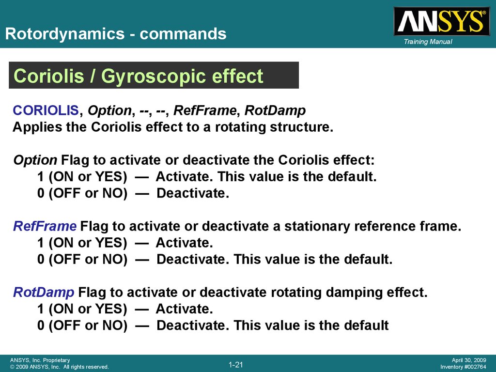
21.
Rotordynamics - commandsTraining Manual
Coriolis / Gyroscopic effect
CORIOLIS, Option, --, --, RefFrame, RotDamp
Applies the Coriolis effect to a rotating structure.
Option Flag to activate or deactivate the Coriolis effect:
1 (ON or YES) — Activate. This value is the default.
0 (OFF or NO) — Deactivate.
RefFrame Flag to activate or deactivate a stationary reference frame.
1 (ON or YES) — Activate.
0 (OFF or NO) — Deactivate. This value is the default.
RotDamp Flag to activate or deactivate rotating damping effect.
1 (ON or YES) — Activate.
0 (OFF or NO) — Deactivate. This value is the default
ANSYS, Inc. Proprietary
© 2009 ANSYS, Inc. All rights reserved.
1-21
April 30, 2009
Inventory #002764
22. Rotordynamics - commands
Eigensolver
Input
Training Manual
Usages
Applicable
Matrices
Extraction
Technique
QR
Damped
MODOPT,
QRDAMP
− Brake squeal and rotordynamics
eigenproblems
− Able to extract complex
eigenvalues resulting from
damping in the system (ALPHAD,
BETAD, etc. )
− Performance is similar to Block
Lanczos
− Good for up to, say 1 million
DOF’s extracting, say less than
100 modes.
K, C, M
(non-symmetric
except M)
Block lanczos and QR
algorithm for the modal
subspace matrices
Damped
MODOPT,
DAMP
− Rotordynamics eigenproblems
− Noise Vibration Harshness
(NVH) problems with structural
acoustics coupling and damping
− Optimal performance up to
about 200K DOF’s, extracting, say
100 modes
− Doesn’t support modal
superposition transient or
harmonic analysis
K, C, M
(non-symmetric)
A subspace method based
on Variational
Technology (VT)
algorithm
ANSYS, Inc. Proprietary
© 2009 ANSYS, Inc. All rights reserved.
1-22
April 30, 2009
Inventory #002764
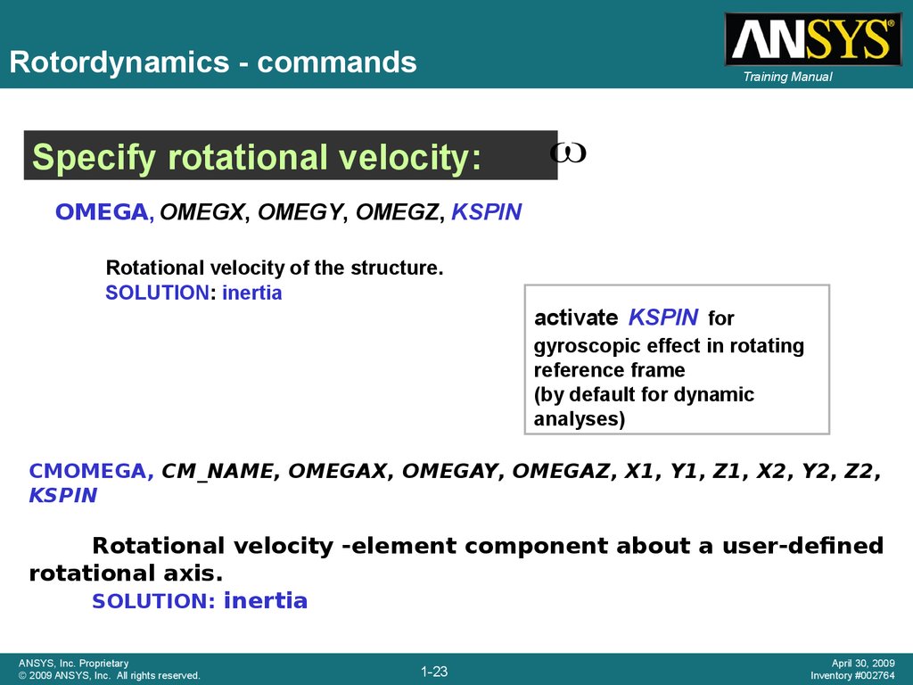
23.
Rotordynamics - commandsTraining Manual
Specify rotational velocity:
ω
OMEGA, OMEGX, OMEGY, OMEGZ, KSPIN
Rotational velocity of the structure.
SOLUTION: inertia
activate KSPIN for
gyroscopic effect in rotating
reference frame
(by default for dynamic
analyses)
CMOMEGA, CM_NAME, OMEGAX, OMEGAY, OMEGAZ, X1, Y1, Z1, X2, Y2, Z2,
KSPIN
Rotational velocity -element component about a user-defined
rotational axis.
SOLUTION: inertia
ANSYS, Inc. Proprietary
© 2009 ANSYS, Inc. All rights reserved.
1-23
April 30, 2009
Inventory #002764
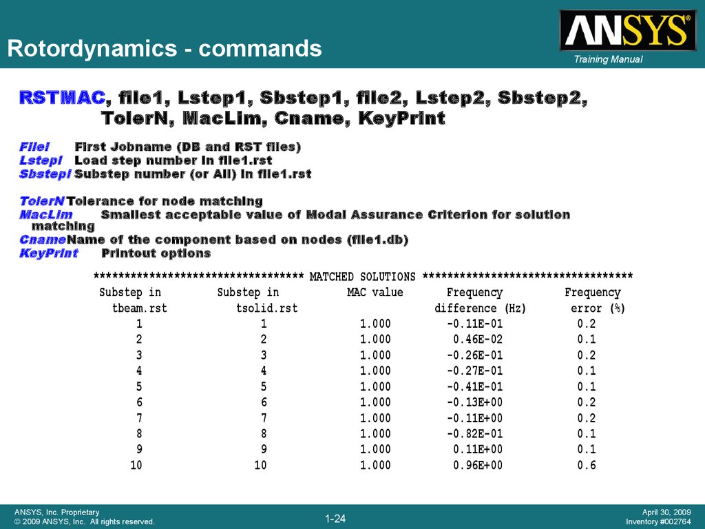
24.
Rotordynamics - commandsTraining Manual
RSTMAC, file1, Lstep1, Sbstep1, file2, Lstep2, Sbstep2,
TolerN, MacLim, Cname, KeyPrint
Filei
First Jobname (DB and RST files)
Lstepi Load step number in file1.rst
Sbstepi Substep number (or All) in file1.rst
TolerN Tolerance for node matching
MacLim
Smallest acceptable value of Modal Assurance Criterion for solution
matching
Cname Name of the component based on nodes (file1.db)
KeyPrint
Printout options
********************************** MATCHED SOLUTIONS **********************************
Substep in
Substep in
MAC value
Frequency
Frequency
tbeam.rst
tsolid.rst
difference (Hz)
error (%)
1
1
1.000
-0.11E-01
0.2
2
2
1.000
0.46E-02
0.1
3
3
1.000
-0.26E-01
0.2
4
4
1.000
-0.27E-01
0.1
5
5
1.000
-0.41E-01
0.1
6
6
1.000
-0.13E+00
0.2
7
7
1.000
-0.11E+00
0.2
8
8
1.000
-0.82E-01
0.1
9
9
1.000
0.11E+00
0.1
10
10
1.000
0.96E+00
0.6
ANSYS, Inc. Proprietary
© 2009 ANSYS, Inc. All rights reserved.
1-24
April 30, 2009
Inventory #002764
25. Rotordynamics - Campbell diagram
Training ManualCampbell diagram
• Variation of the rotor natural frequency with respect to rotor speed ω
• In modal analysis perform multiple load steps at different angular
velocities ω
• Campbell commands
– CAMPB: support Campbell for prestressed structures (/SOLU)
– PLCAMP: display Campbell diagram
(/POST1)
– PRCAMP: print frequencies and critical speeds
(/POST1)
ANSYS, Inc. Proprietary
© 2009 ANSYS, Inc. All rights reserved.
1-25
April 30, 2009
Inventory #002764
26. Rotordynamics - Campbell diagram
Training ManualCampbell diagram
PLCAMP, Option, SLOPE, UNIT, FREQB, Cname,
STABVAL
Option
Flag to activate or deactivate sorting
SLOPE
The slope of the line which represents the
number of excitations per revolution of the rotor.
UNIT
Specifies the unit of measurement for rotational
angular velocities
FREQB
The beginning, or lower end, of the frequency
range of interest.
Cname
The rotating component name
STABVAL
Plot the real part of the eigenvalue (Hz)
ANSYS, Inc. Proprietary
© 2009 ANSYS, Inc. All rights reserved.
1-26
April 30, 2009
Inventory #002764
27. Rotordynamics – multi-spool rotors
Training ManualMore than 1 spool and / or non-rotating parts, use components
(CM) and component rotational velocities (CMOMEGA).
PLCAMP, Option, SLOPE, UNIT, FREQB, Cname
component name
SPOOL1
ANSYS, Inc. Proprietary
© 2009 ANSYS, Inc. All rights reserved.
1-27
April 30, 2009
Inventory #002764
28. Rotordynamics – multi-spool rotor
Training ManualWhirl animation (ANHARM command)
ANSYS, Inc. Proprietary
© 2009 ANSYS, Inc. All rights reserved.
1-28
April 30, 2009
Inventory #002764
29. Campbell diagrams & whirl
Campbell diagrams & whirlTraining Manual
• Variation of the rotor natural
frequencies with respect to
rotor speed
• In modal analysis perform
multiple load steps at
different angular velocities
• As frequencies split with
increasing spin velocity,
ANSYS identifies:
– forward (FW) and
backward (BW) whirl
– stable / unstable
operation
– critical speeds
• Also available for multispool
models
ANSYS, Inc. Proprietary
© 2009 ANSYS, Inc. All rights reserved.
1-29
April 30, 2009
Inventory #002764
30. Rotor whirl
Training Manual• Forward whirl:
when and the
whirl motion are
rotating in the same
direction
• Backward whirl:
when and the
whirl motion are
rotating in opposite
directions
ANSYS, Inc. Proprietary
© 2009 ANSYS, Inc. All rights reserved.
1-30
April 30, 2009
Inventory #002764
31. Orbit plots
Training Manual• In a plane perpendicular to the
spin axis, the orbit of a node is
an ellipse
• It is defined by three
characteristics: semi axes A, B
and phase in a local
coordinate system (x, y, z) where
x is the rotation axis
• Angle is the initial position of
the node with respect to the
major semi-axis A.
Plot orbit: PLORB
• Orbit plots are available for
beam models
Print orbit: PRORB
ANSYS, Inc. Proprietary
© 2009 ANSYS, Inc. All rights reserved.
1-31
April 30, 2009
Inventory #002764
32. Rotordynamics – forced response
Training ManualPossible excitations caused by rotation velocity are:
– Unbalance ( )
– Coupling misalignment (2* )
– Blade, vane, nozzle, diffusers (s* )
– Aerodynamic excitations as in centrifugal compressors
(0.5* )
ANSYS, Inc. Proprietary
© 2009 ANSYS, Inc. All rights reserved.
1-32
April 30, 2009
Inventory #002764
33. Rotordynamics – forced response
Rotordynamics – forcedforced response
response
Ansys command for
SYNCHRO, ratio,
– ratio
Training Manual
synchronous and asynchronous forces
cname
• The ratio between the frequency of excitation, f, and the frequency of the rotational velocity of the
structure.
– Cname
• The name of the rotating component on which to apply the harmonic excitation.
Note: The SYNCHRO command is valid only for full harmonic analysis (HROPT,Method =
FULL)
= 2πf / ratio
where, f = excitation frequency (defined in HARFRQ)
The rotational velocity, ω, is applied along the direction cosines of the
rotation axis (specified via an OMEGA or CMOMEGA command)
ANSYS, Inc. Proprietary
© 2009 ANSYS, Inc. All rights reserved.
1-33
April 30, 2009
Inventory #002764
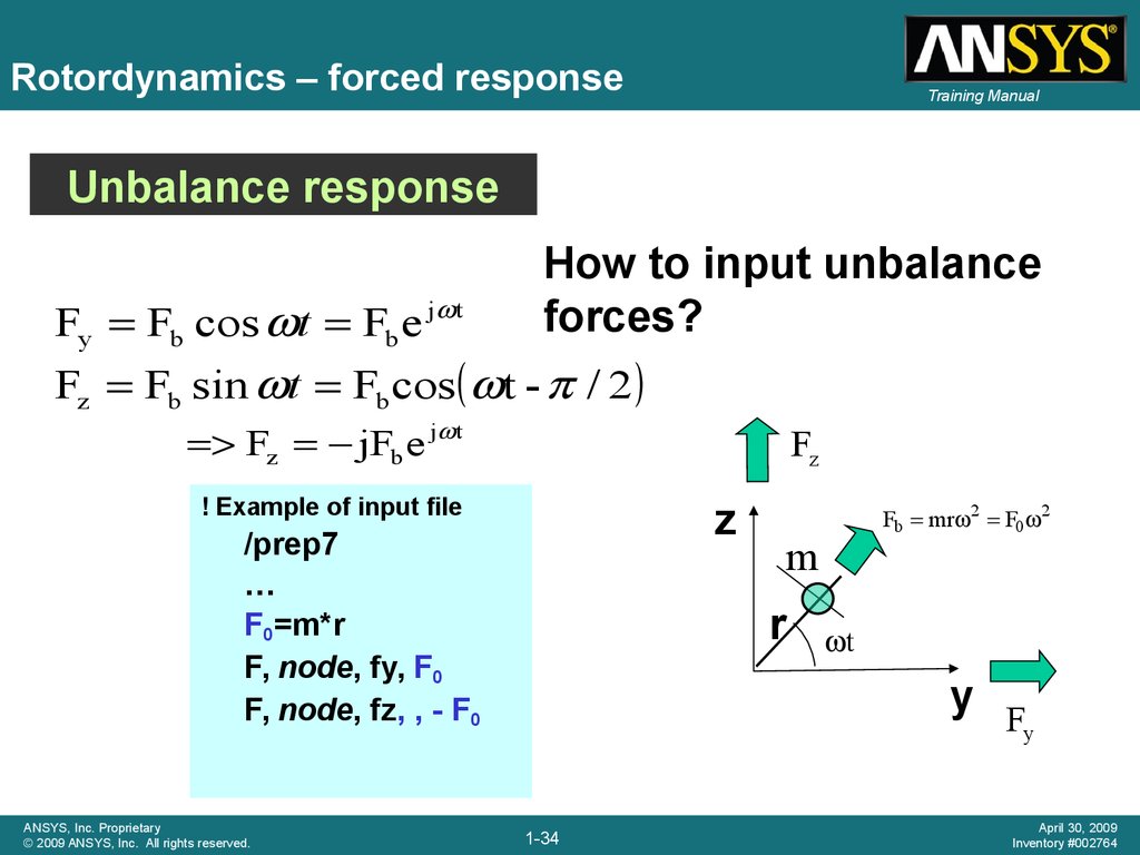
34.
Rotordynamics – forced responseTraining Manual
Unbalance response
Fy Fb cos t Fb e j t
How to input unbalance
forces?
Fz Fb sin t Fb cos t - / 2
Fz jFb e j t
Fz
! Example of input file
z
/prep7
…
F0=m*r
F, node, fy, F0
F, node, fz, , - F0
ANSYS, Inc. Proprietary
© 2009 ANSYS, Inc. All rights reserved.
Fb mr 2 F0 2
m
r
t
y F
y
1-34
April 30, 2009
Inventory #002764
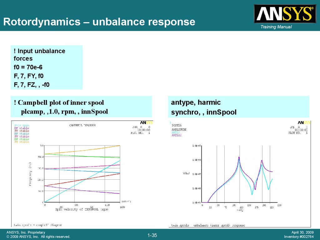
35.
Rotordynamics – unbalance responseTraining Manual
! Input unbalance
forces
f0 = 70e-6
F, 7, FY, f0
F, 7, FZ, , -f0
antype, harmic
synchro, , innSpool
! Campbell plot of inner spool
plcamp, ,1.0, rpm, , innSpool
ANSYS, Inc. Proprietary
© 2009 ANSYS, Inc. All rights reserved.
1-35
April 30, 2009
Inventory #002764
36. Stability
Training Manual• Self-excited vibrations in a rotating structure cause an increase of the
vibration amplitude over time such as shown below.
• Such instabilities, if unchecked, can result in equipment damage.
• The most common sources of instability are:
– Bearing characteristics
– Internal rotating damping (material damping)
– Contact between rotating and static parts
• Instabilities can be identified by performing a transient analysis or a modal
analysis (complex frequencies)
ANSYS, Inc. Proprietary
© 2009 ANSYS, Inc. All rights reserved.
1-36
April 30, 2009
Inventory #002764
37. Stability
ANSYS, Inc. Proprietary© 2009 ANSYS, Inc. All rights reserved.
Training Manual
1-37
April 30, 2009
Inventory #002764
38. Stability
Training ManualStable at 30,000
rpm (3141.6 rad/sec)
ANSYS, Inc. Proprietary
© 2009 ANSYS, Inc. All rights reserved.
Unstable at 60,000
rpm (6283.2 rad/sec)
1-38
April 30, 2009
Inventory #002764
39. Rotordynamics analysis guide
Training Manual• New at release
12.0
• Provides a
detailed
description of
capabilities
• Provides
guidelines for
rotordynamics
model setup
ANSYS, Inc. Proprietary
© 2009 ANSYS, Inc. All rights reserved.
1-39
April 30, 2009
Inventory #002764
40. Sample models available
ANSYS, Inc. Proprietary© 2009 ANSYS, Inc. All rights reserved.
Training Manual
1-40
April 30, 2009
Inventory #002764
41. Some examples
© 2009 ANSYS, Inc. All rights reserved.1-41
ANSYS, Inc. Proprietary
42. Validation examples
© 2009 ANSYS, Inc. All rights reserved.1-42
ANSYS, Inc. Proprietary
43. Generic validation model
Training Manual• Modal analysis of a
3D beam (solid
elements), =30000
rpm
• Excellent agreement
between simulation
and theory
• Ref: Gerhard Sauer & Michael
Wolf, ‘FEA of Gyroscopic
effects,’ Finite Elements in
Analysis & Design, 5, (1989),
131-140
ANSYS, Inc. Proprietary
© 2009 ANSYS, Inc. All rights reserved.
1-43
April 30, 2009
Inventory #002764
44. Nelson rotor (beams & bearings)
Nelson rotor (beams & bearings)Training Manual
Damped Natural Frequencies (Hz)
Whirl
0 rpm
70,000 rpm
[1]
Ansys
F (Hz)
Ansys
[1]
Ansys
[1]
1
BW
BW
271.2
271.1
214.5
213.6
2
FW
FW
271.2
271.1
329.8
330.6
3
BW
BW
808.8
806.4
762.4
760.0
4
FW
FW
808.8
806.4
844.9
842.6
5
BW
BW
1272.0
1273.0
1068.7
1066.5
6
FW
FW
1272.0
1273.0
1516.2
1522.0
Critical speeds (rpm)
Ansys
[1]
15,494
15,470
17,146
17,159
46,729
46,612
50,114
49,983
64,924
64,752
95,747
96,457
ANSYS, Inc. Proprietary
© 2009 ANSYS, Inc. All rights reserved.
Ref. [1]: ‘Dynamics of
rotor-bearing systems
using finite elements,’ J.
of Eng. for Ind., May
1976
1-44
April 30, 2009
Inventory #002764
45. Instability analysis – transient analysis
Training Manual30,000 rpm; closed
trajectory: stable
Rotor with unsymmetrical
bearings
ANSYS, Inc. Proprietary
© 2009 ANSYS, Inc. All rights reserved.
60,000 rpm; open
trajectory: unstable
1-45
April 30, 2009
Inventory #002764
46. Instability analysis – modal analysis
Training Manual30,000
30,000
rpm
rpm
All complex frequencies’ real
parts are negative: stable
60,000
60,000
rpm
rpm
Results obtained from a
modal analysis with QRDAMP
solver
One complex frequency has a
positive real part: unstable
ANSYS, Inc. Proprietary
© 2009 ANSYS, Inc. All rights reserved.
1-46
April 30, 2009
Inventory #002764
47. Effect of rotating damping
© 2009 ANSYS, Inc. All rights reserved.1-47
ANSYS, Inc. Proprietary
48. Rotating damping example
Training Manual• Comparison of the dynamics of a
simple model with and without
rotating damping effect activated:
– Rotating beam
– Isotropic bearings
– Proportional damping
• Ref: ANSYS VM 261
• E.S. Zorzi, H.D. Nelson, “Finite element simulation of rotorbearing systems with internal damping,” ASME Journal of
Engineering for Power, Vol. 99, 1976, pg 71-76.
ANSYS, Inc. Proprietary
© 2009 ANSYS, Inc. All rights reserved.
1-48
April 30, 2009
Inventory #002764
49. Campbell diagrams
Training ManualNo damping
With damping
Frequencies
Stability
ANSYS, Inc. Proprietary
© 2009 ANSYS, Inc. All rights reserved.
All
All
modes
modes
are
are
stable
stable
1-49
Instable
Instable
modes
modes
April 30, 2009
Inventory #002764
50. Transient analysis
Training ManualNo damping
With damping
Closed
Closed
trajector
trajector
y, stable
stable
y,
ANSYS, Inc. Proprietary
© 2009 ANSYS, Inc. All rights reserved.
1-50
Open
Open
trajector
trajector
y,
y,
unstable
unstable
April 30, 2009
Inventory #002764
51. Rotordynamics with ANSYS Workbench
© 2009 ANSYS, Inc. All rights reserved.1-51
ANSYS, Inc. Proprietary
52. Geometry & model definition
Geometry & model definitionTraining Manual
• The database
contains a
generic steel
rotor created in
ANSYS
DesignModeler
to which two
“Springs to
Ground” have
been added.
ANSYS, Inc. Proprietary
© 2009 ANSYS, Inc. All rights reserved.
1-52
April 30, 2009
Inventory #002764
53. Bearing definition
Training Manual• The standard
Simulation
springs are
changed to
bearing
elements
utilizing the
parameter, _sid
to change the
spring element
types to 214.
• The stiffness
and damping
values are
defined with the
input argument
values shown in
the Details
window.
ANSYS, Inc. Proprietary
© 2009 ANSYS, Inc. All rights reserved.
1-53
April 30, 2009
Inventory #002764
54. Solution settings for modal analysis
Training Manual• A commands object inserted into the analysis branch switches the default modal
solver to QRDAMP and requests complex mode shapes.
• A spin rate of 100 radians per sec. is specified about the z axis and coriolis
effects in the stationary reference frame are requested.
ANSYS, Inc. Proprietary
© 2009 ANSYS, Inc. All rights reserved.
1-54
April 30, 2009
Inventory #002764
55. Solution information
Training Manual• While the solution is running,
the solution output can be
monitored.
• The output shown is the
undamped and damped
frequencies.
• The real component of the
complex frequency is the
stability number, the
exponent in the expression
for damped free vibration.
• A negative number indicates
the mode is stable.
ANSYS, Inc. Proprietary
© 2009 ANSYS, Inc. All rights reserved.
1-55
April 30, 2009
Inventory #002764
56. Modal results
Training Manual• Complex
modal results
are shown in
the tabular
view of the
results.
• Complex
eigenshapes
can be
animated.
ANSYS, Inc. Proprietary
© 2009 ANSYS, Inc. All rights reserved.
1-56
April 30, 2009
Inventory #002764
57. Animated modal shape
ANSYS, Inc. Proprietary© 2009 ANSYS, Inc. All rights reserved.
Training Manual
1-57
April 30, 2009
Inventory #002764
58. Compressor model Solid model & casing simulation
Compressor modelSolid model & casing simulation
© 2009 ANSYS, Inc. All rights reserved.
1-58
ANSYS, Inc. Proprietary
59. Compressor: free-free testing apparatus used for initial model calibration
Training Manual+Z
Courtesy of Trane, a business of American Standard, Inc.
ANSYS, Inc. Proprietary
© 2009 ANSYS, Inc. All rights reserved.
1-59
April 30, 2009
Inventory #002764
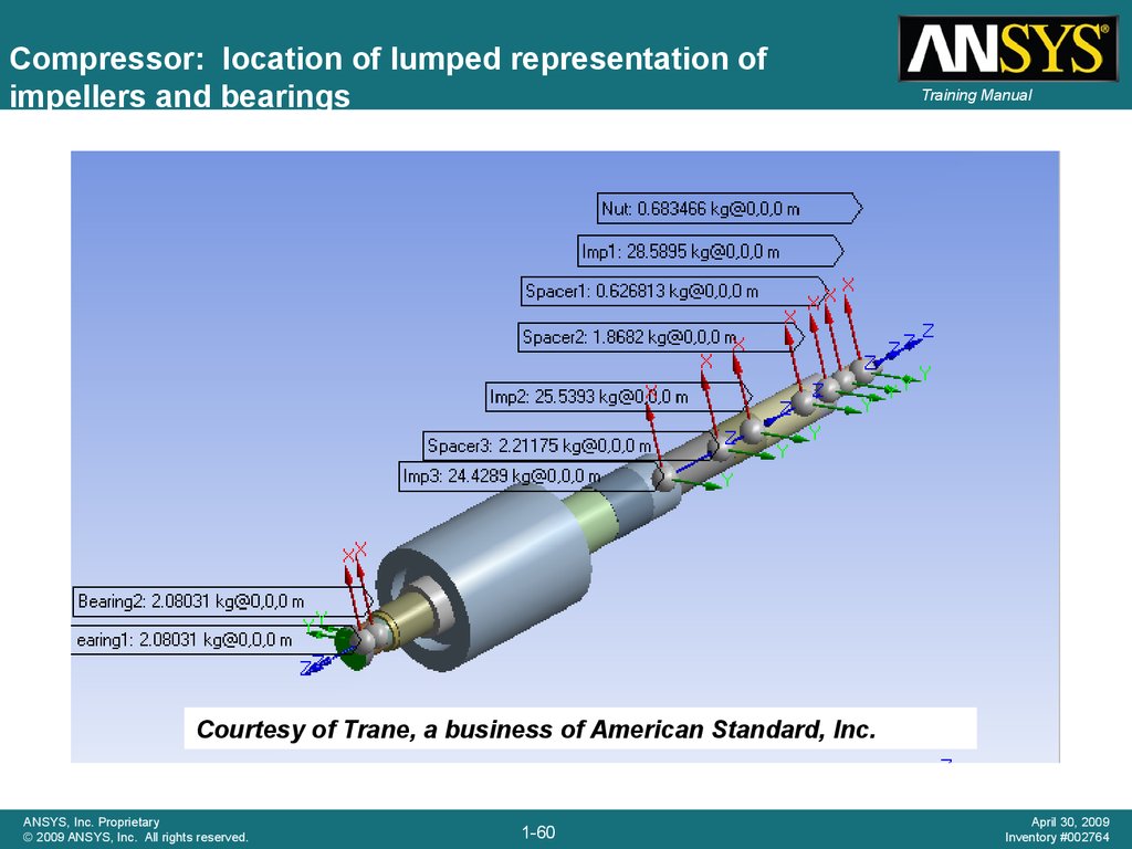
60.
Compressor: location of lumped representation ofimpellers and bearings
Training Manual
Courtesy of Trane, a business of American Standard, Inc.
ANSYS, Inc. Proprietary
© 2009 ANSYS, Inc. All rights reserved.
1-60
April 30, 2009
Inventory #002764
61. Compressor: SOLID185 mesh of shaft
Training ManualVery stiff symmetric
contact between axial
segments
ANSYS, Inc. Proprietary
© 2009 ANSYS, Inc. All rights reserved.
1-61
April 30, 2009
Inventory #002764
62. Compressor: forward whirl mode
Training ManualCourtesy of Trane, a business of American Standard, Inc.
ANSYS, Inc. Proprietary
© 2009 ANSYS, Inc. All rights reserved.
1-62
April 30, 2009
Inventory #002764
63. Compressor: backward whirl mode
Training ManualCourtesy of Trane, a business of American Standard, Inc.
ANSYS, Inc. Proprietary
© 2009 ANSYS, Inc. All rights reserved.
1-63
April 30, 2009
Inventory #002764
64. Compressor: Campbell diagram with variable bearings
ANSYS, Inc. Proprietary© 2009 ANSYS, Inc. All rights reserved.
1-64
Training Manual
April 30, 2009
Inventory #002764
65. Solid model of rotor with chiller assembly
Training ManualCourtesy of Trane, a business of American Standard, Inc.
ANSYS, Inc. Proprietary
© 2009 ANSYS, Inc. All rights reserved.
1-65
April 30, 2009
Inventory #002764
66. Meshed rotor and chiller assembly
Training ManualCourtesy of Trane, a business of American Standard, Inc.
ANSYS, Inc. Proprietary
© 2009 ANSYS, Inc. All rights reserved.
1-66
April 30, 2009
Inventory #002764
67. Analysis model – supporting structure represented by CMS superelement
Training ManualFinite element model of
rotor and impellers
Housing and entire chiller
assembly represented by
a CMS superelement
Courtesy of Trane, a business of American Standard, Inc.
ANSYS, Inc. Proprietary
© 2009 ANSYS, Inc. All rights reserved.
1-67
April 30, 2009
Inventory #002764
68. Analysis model
Training ManualBearing
locations
Impellers
Outline of
CMS
superelement
Courtesy of Trane, a business of American Standard, Inc.
ANSYS, Inc. Proprietary
© 2009 ANSYS, Inc. All rights reserved.
1-68
April 30, 2009
Inventory #002764
69. Typical mode animation
Training ManualCourtesy of Trane, a business of American Standard, Inc.
ANSYS, Inc. Proprietary
© 2009 ANSYS, Inc. All rights reserved.
1-69
April 30, 2009
Inventory #002764
70. Blower shaft model Transient startup & effect of prestress
Blower shaft modelTransient startup & effect of prestress
© 2009 ANSYS, Inc. All rights reserved.
1-70
ANSYS, Inc. Proprietary
71. Blower shaft - model
Training ManualImpeller to pump hot hydrogen
rich mix of gas and liquid into
solid oxyde fluid cell
Spin 10,000 rpm
ANSYS model of
rotating part
99 beam elements & 2
bearing elements
ANSYS, Inc. Proprietary
© 2009 ANSYS, Inc. All rights reserved.
1-71
April 30, 2009
Inventory #002764
72. Blower shaft - modal analysis
Training ManualFrequencies and corresponding mode shapes orbits
ANSYS, Inc. Proprietary
© 2009 ANSYS, Inc. All rights reserved.
1-72
April 30, 2009
Inventory #002764
73. Blower shaft – modal analysis
Training ManualStability
Frequencies
ANSYS, Inc. Proprietary
© 2009 ANSYS, Inc. All rights reserved.
1-73
April 30, 2009
Inventory #002764
74. Blower shaft – critical speed
ANSYS, Inc. Proprietary© 2009 ANSYS, Inc. All rights reserved.
Training Manual
1-74
April 30, 2009
Inventory #002764
75. Blower shaft – unbalance response
Training ManualHarmonic response to disk unbalance
- Disk eccentricity is .002”
- Disk mass is .0276 lbf-s2/in.
- Sweep frequencies 0-10000 rpm
Amplitude of displacement at disk
ANSYS, Inc. Proprietary
© 2009 ANSYS, Inc. All rights reserved.
1-75
Orbits at critical speed
April 30, 2009
Inventory #002764
76. Blower Shaft – unbalance response
Training ManualBearings reactions
Forward bearing
is more loaded
than rear one as
first mode is a
disk mode.
ANSYS, Inc. Proprietary
© 2009 ANSYS, Inc. All rights reserved.
1-76
April 30, 2009
Inventory #002764
77. Blower shaft – start up
Training ManualTransient analysis
- Ramped rotational velocity over 4 seconds
- Unbalance transient forces FY and FZ at disk
Zoom of
transient
force
ANSYS, Inc. Proprietary
© 2009 ANSYS, Inc. All rights reserved.
1-77
April 30, 2009
Inventory #002764
78. Blower shaft – start up
Training ManualDisplacement UY and UZ at disk
zoom on critical speed passage
Amplitude of
displacement at disk
Ampl U y2 U z2
ANSYS, Inc. Proprietary
© 2009 ANSYS, Inc. All rights reserved.
1-78
April 30, 2009
Inventory #002764
79. Blower shaft – start up
Training ManualTransient orbits
0 to 4 seconds
3 to 4 seconds
As bearings are symmetric, orbits are circular
ANSYS, Inc. Proprietary
© 2009 ANSYS, Inc. All rights reserved.
1-79
April 30, 2009
Inventory #002764
80. Blower shaft – prestress
Training ManualInclude prestress due to thermal loading:
Thermal body load up to 1500 deg F
Resulting static displacements
ANSYS, Inc. Proprietary
© 2009 ANSYS, Inc. All rights reserved.
1-80
April 30, 2009
Inventory #002764
81. Blower shaft – Campbell diagram comparison
No prestressANSYS, Inc. Proprietary
© 2009 ANSYS, Inc. All rights reserved.
Training Manual
With thermal prestress
1-81
April 30, 2009
Inventory #002764
82. Demo’s Agenda
Training Manual• 3D model
• Point mass by user
• Automatic Rigid Body
• B.C. / Remote displacement
• Bearing (Combi214)
• Joint (Cylindrical, Spherical, BUSHING)
Relative to ground / to stator
ANSYS, Inc. Proprietary
© 2009 ANSYS, Inc. All rights reserved.
1-82
April 30, 2009
Inventory #002764
83. Rotordynamics with ANSYS Workbench A workflow example
© 2009 ANSYS, Inc. All rights reserved.1-83
ANSYS, Inc. Proprietary
84. Storyboard
Training Manual• The geometry is provided in form of a Parasolid file
• Part of the shaft must be reparametrized to allow for diameter
variations
• A disk must be added to the geometry
• Simulation will be performed using the generalized axisymmetric
elements, mixing WB features and APDL scripting
• Design analysis will be made with variations of bearings properties
and geometry
ANSYS, Inc. Proprietary
© 2009 ANSYS, Inc. All rights reserved.
1-84
April 30, 2009
Inventory #002764
85. Project view
Training Manual• Upper part of the schematics
defines the simulation process
(geometry to mesh to
simulation)
Parameters of the model are
gathered in one location
(geometry, bearing stiffness)
Lower part of the schematics
contains the design
exploration tools
ANSYS, Inc. Proprietary
© 2009 ANSYS, Inc. All rights reserved.
1-85
April 30, 2009
Inventory #002764
86. Geometry setup
Training Manual• Geometry is
imported in Design
Modeler
• A part of the shaft
is redesigned with
parametric
dimensions
• Model is sliced to
be used with
axisymmetric
elements
• Bearing locations
are defined
• A disc is added to
the geometry
Initial 3D geometry
Final axisymmetric model
Additional disk
Bearings location
ANSYS, Inc. Proprietary
© 2009 ANSYS, Inc. All rights reserved.
1-86
April 30, 2009
Inventory #002764
87. Geometry details
Training Manual3D Model sliced to create
axisymmetric model
Part of the original shaft is
removed and recreated with
parametric radius
Additional disk created with
parameters (the outer diameter
will be used for design analysis)
ANSYS, Inc. Proprietary
© 2009 ANSYS, Inc. All rights reserved.
Bearing locations and named selections are created (named selections
will be transferred as node components for the simulation)
1-87
April 30, 2009
Inventory #002764
88. Mesh
Training Manual• The model is
meshed using the
WB meshing tools
ANSYS, Inc. Proprietary
© 2009 ANSYS, Inc. All rights reserved.
1-88
April 30, 2009
Inventory #002764
89. Simulation
Training Manual• Simulation is
performed using an
APDL script that
defines:
– Element types
– Bearings
– Boundary
conditions
– Solutions settings
(Qrdamp solver…)
– Post-processing
(Campbell plots
and extraction of
critical speeds)
Axisymmetric model
with boundary
conditions
Expanded view
ANSYS, Inc. Proprietary
© 2009 ANSYS, Inc. All rights reserved.
1-89
April 30, 2009
Inventory #002764
90. APDL script
Training ManualMesh transferred
as mesh200
elements,
converted to
solid272
Spring1 component
comes from named
selection
ANSYS, Inc. Proprietary
© 2009 ANSYS, Inc. All rights reserved.
1-90
April 30, 2009
Inventory #002764
91. Simulation results
Training Manual• The APDL scripts
can create plots
and animations
• The results can
also be analyzed
within the
Mechanical APDL
interface
• Results are
extracted using
*get commands
and exposed as
WB parameters
(showing the
performance of
the design)
ANSYS, Inc. Proprietary
© 2009 ANSYS, Inc. All rights reserved.
1-91
April 30, 2009
Inventory #002764
92. Mode animation (expanded view)
ANSYS, Inc. Proprietary© 2009 ANSYS, Inc. All rights reserved.
1-92
Training Manual
April 30, 2009
Inventory #002764
93. Design exploration
Training Manual• The model has 2 geometry
parameters (disc and shaft
radius) as well as a stiffness
parameters (bearings stiffness)
• 4 output parameters are
investigated: first and second
critical speeds at 2xRPM and
4xRPM (obtained from
theCampbell diagrams and
*get commands)
ANSYS, Inc. Proprietary
© 2009 ANSYS, Inc. All rights reserved.
1-93
April 30, 2009
Inventory #002764
94. Sample results
Training Manual• A response surface of
the model is created
using a Design of
Experiments
Sensitivity plots:
the bearing
stiffness has no
influence on the
first and second
critical speeds,
the disc radius is
the key
parameter
• Curves, surfaces and
sensitivity plots are
created and the design
can be investigated
Evolution of
critical speed
with shaft and
disc radius
• Optimization tools are
also available
ANSYS, Inc. Proprietary
© 2009 ANSYS, Inc. All rights reserved.
1-94
April 30, 2009
Inventory #002764
95. Optimization
Training Manual• A multi-objective
optimization is
described and
possible
candidates are
found (usually,
there are
multiple
acceptable
configurations)
• Trade-off plots
give an
indication about
the achievable
performance
ANSYS, Inc. Proprietary
© 2009 ANSYS, Inc. All rights reserved.
1-95
April 30, 2009
Inventory #002764