


 physics
 electronics
Similar presentations:


PID controller Design
1.
Review past lectures & Continuation ofPID Controller Design
Md Hazrat Ali
Department of Mechanical Engineering
School of Engineering,
Nazarbayev University
2.
Today’s Quote:“Good, better, best. Never let it rest. Til your good is better
and your better is best.”
― St. Jerome
3.
Classical ControllerPID Controller4.
IntroductionDesign PID control
Know mathematical model various design techniques
Plant is complicated, can’t obtain mathematical model
experimental approaches to the tuning of PID controllers
5. PID Control
PID ControlA closed loop (feedback) control system, generally with
Single InputSingle Output (SISO)
A portion of the signal being fed back is:
Proportional to the signal (P)
Proportional to integral of the signal (I)
Proportional to the derivative of the signal (D)
6. Output equation of PID controller in time domain
7.
The Characteristics of P, I, and D controllersCL RESPONSE
RISE TIME
OVERSHOOT
SETTLING TIME
S-S ERROR
Kp
Decrease
Increase
Small Change
Decrease
Ki
Decrease
Increase
Increase
Eliminate
Kd
Small Change
Decrease
Decrease
Small Change
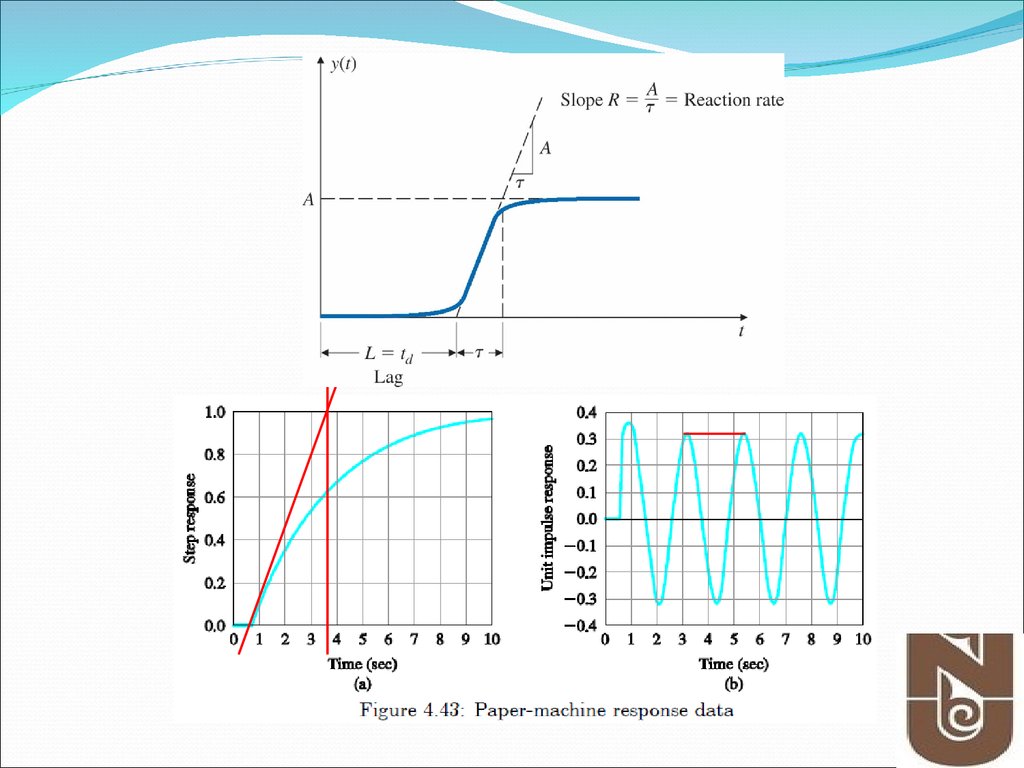
8. Figure 4.11 Process reaction curve
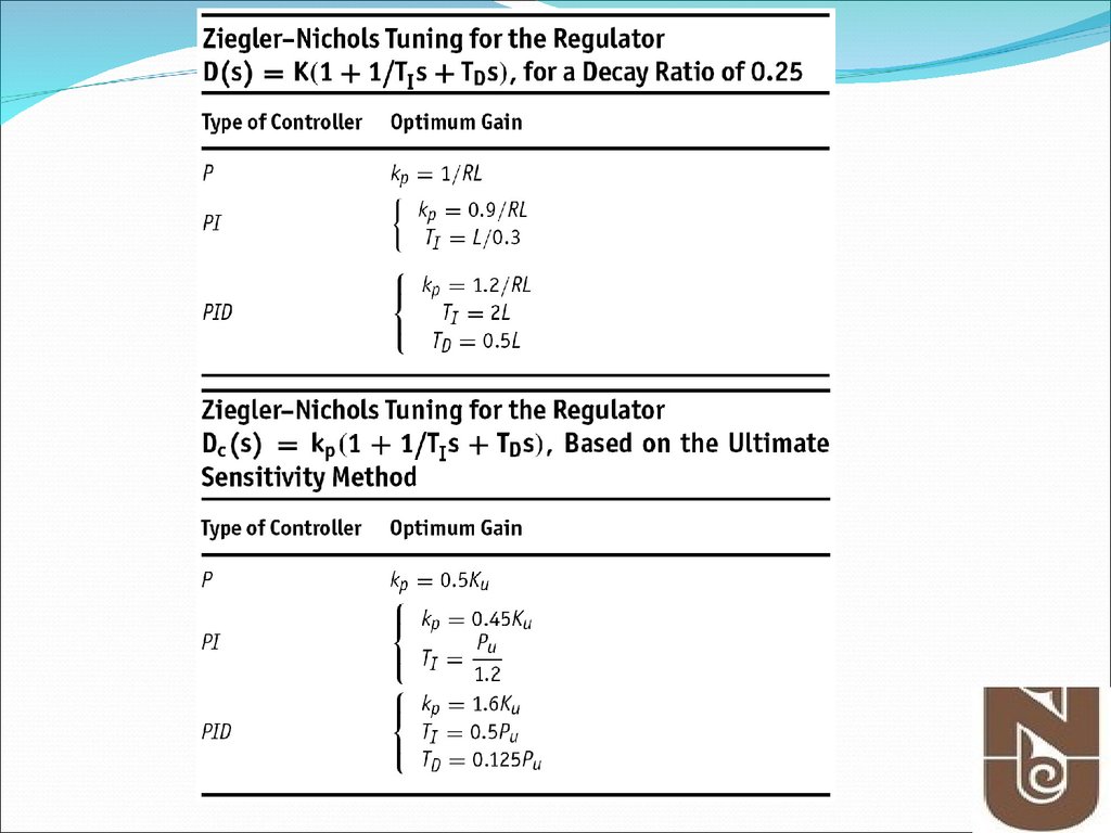
PID Controller- Ziegler Method #1Figure 4.11 Process reaction curve
9.
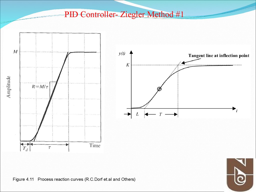
PID Controller- Ziegler Method #1Figure 4.11 Process reaction curves (R.C.Dorf et.al and Others)
10. Figure 4.12 Quarter decay ratio
PID Controller- Ziegler Method #1Figure 4.12 Quarter decay ratio
11.
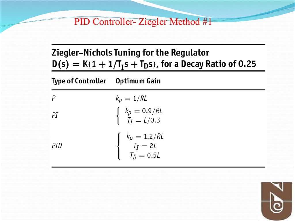
PID Controller- Ziegler Method #112. Figure 4.13 Determination of ultimate gain and period
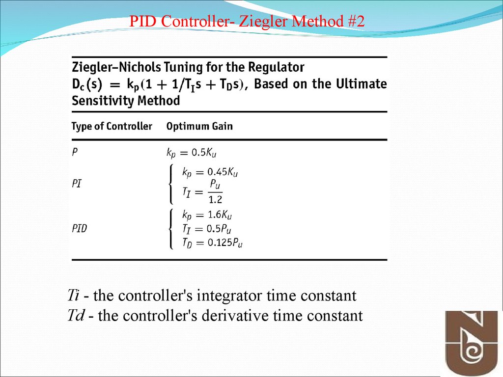
PID Controller- Ziegler Method #2Figure 4.13 Determination of ultimate gain and period
13. Figure 4.14 Neutrally stable system
PID Controller- Ziegler Method #2Figure 4.14 Neutrally stable system
14.
PID Controller- Ziegler Method #2Ti - the controller's integrator time constant
Td - the controller's derivative time constant
15.
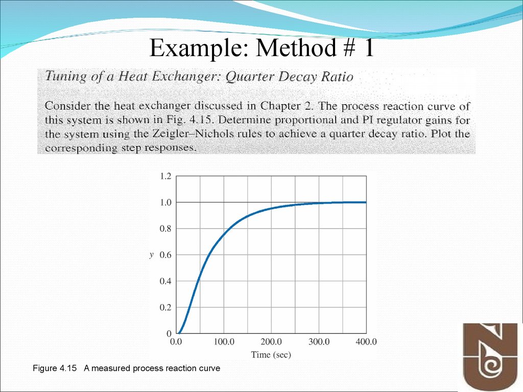
Example: Method # 1Figure 4.15 A measured process reaction curve
16.
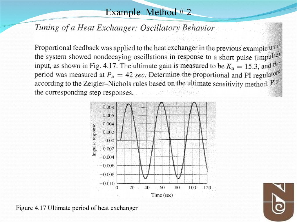
Example: Method # 2Figure 4.17 Ultimate period of heat exchanger
17.
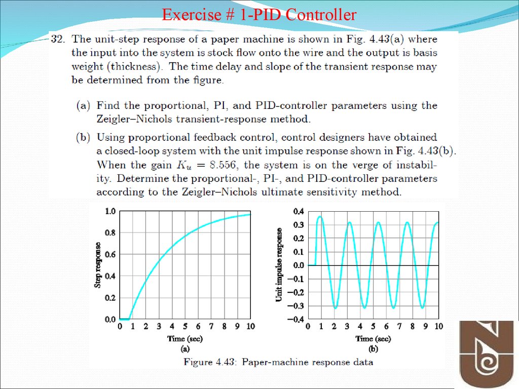
Exercise # 1-PID Controller18.
19.
20.
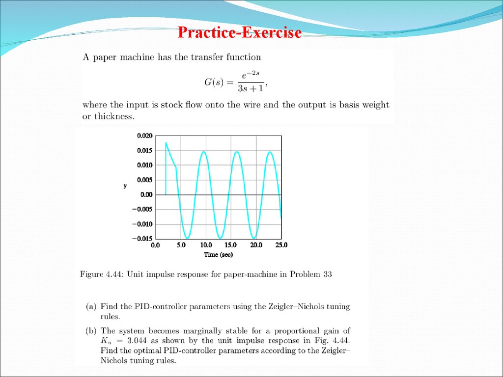
Practice-Exercise21. Further Reading
Franklin, et. al., Chapter 4Section 4.3
Richard C. Dorf et.al, Chapter 6,
Chapter 6.2