


 chemistry
Similar presentations:


![A structural specificity of radical cation salts based on BEDT-TTF with [ReX6]2- (X=Cl or Br) anion](https://cf2.ppt-online.org/files2/thumb/y/yf3MOn0a7lkIvUr28jmYWBtQGJKT5zHNAxc1dV.jpg "A structural specificity of radical cation salts based on BEDT-TTF with [ReX6]2- (X=Cl or Br) anion")
The structure of Metals
1.
CHAPTER 3: The STRUCTURE ofMetals
ISSUES TO ADDRESS...
• How do atoms assemble into solid structures?
(for now, focus on metals)
• How does the density of a material depend on
its structure?
• When do material properties vary with the
sample (i.e., part) orientation?
Chapter 3-1
2.
Chapter 3-23.
Chapter 3-34.
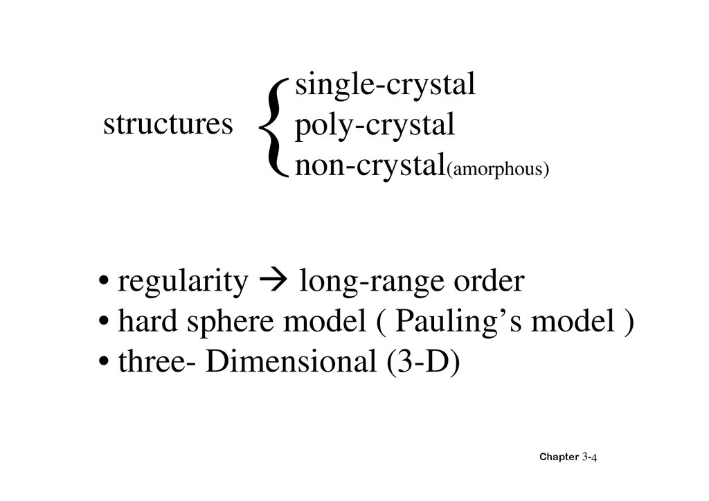
structuressingle-crystal
poly-crystal
non-crystal(amorphous)
• regularity long-range order
• hard sphere model ( Pauling’s model )
• three- Dimensional (3-D)
Chapter 3-4
5.
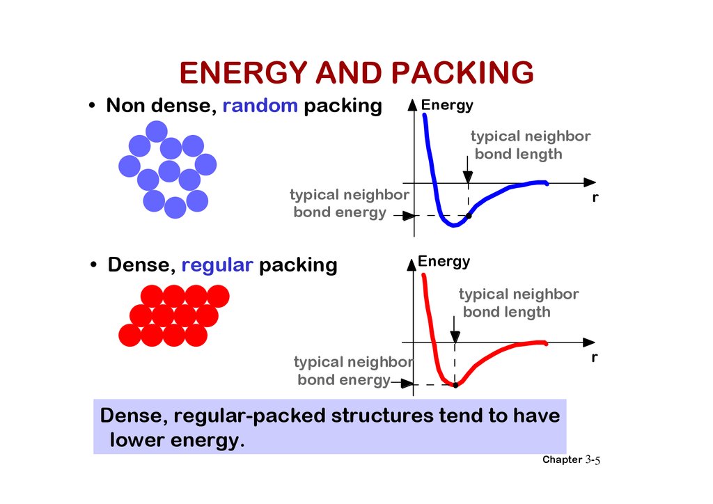
ENERGY AND PACKING• Non dense, random packing
Energy
typical neighbor
bond length
typical neighbor
bond energy
• Dense, regular packing
r
Energy
typical neighbor
bond length
r
typical neighbor
bond energy
Dense, regular-packed structures tend to have
lower energy.
Chapter 3-5
6.
MATERIALS AND PACKINGCrystalline materials...
• atoms pack in periodic, 3D arrays
• typical of: -metals
-many ceramics
-some polymers
crystalline SiO2
Adapted from Fig. 3.18(a),
Callister 6e.
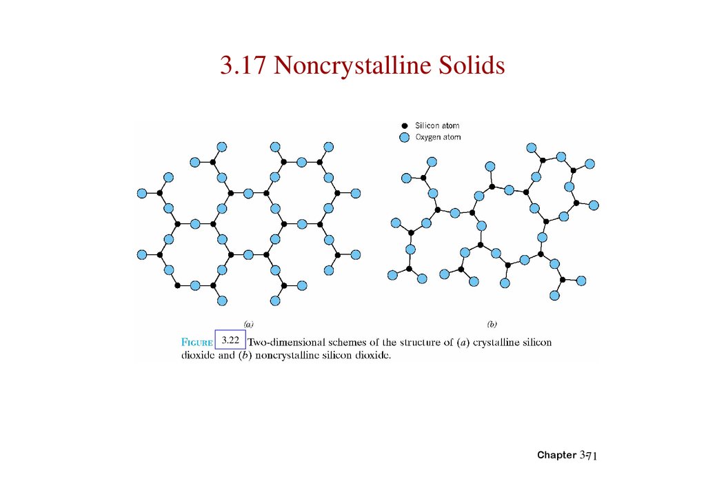
Noncrystalline materials...
• atoms have no periodic packing
• occurs for: -complex structures
-rapid cooling
"Amorphous" = Noncrystalline
Si
Oxygen
noncrystalline SiO2
Adapted from Fig. 3.18(b),
Callister 6e.
Chapter 3-6
7.
3.1 Introduction• Various types of atomic bonding
• Unit cell
• Three common crystal structures found in
metals
• Crystallographic points, directions, and
planes
Chapter 3-7
8.
Crystal Structures3.2 Fundamental Concepts
• A crystalline material is one in which the atoms
are situated in repeating or periodic array over
large atomic distances.
• Lattice means a three-dimensional array of point
coinciding with atom positions.
Chapter 3-8
9.
3.3 Unit Cells• Crystal structure is often convenient to
subdivide the structure into a small repeat
entities called unit cells.
Chapter 3-9
10.
3.4 METALLIC CRYSTAL Structures• tend to be densely packed.
• have several reasons for dense packing:
-Typically, only one element is present, so all atomic
radii are the same.
-Metallic bonding is not directional.
-Nearest neighbor distances tend to be small in
order to lower bond energy.
• have the simplest crystal structures.
We will look at three such structures...
Chapter 3-10
11.
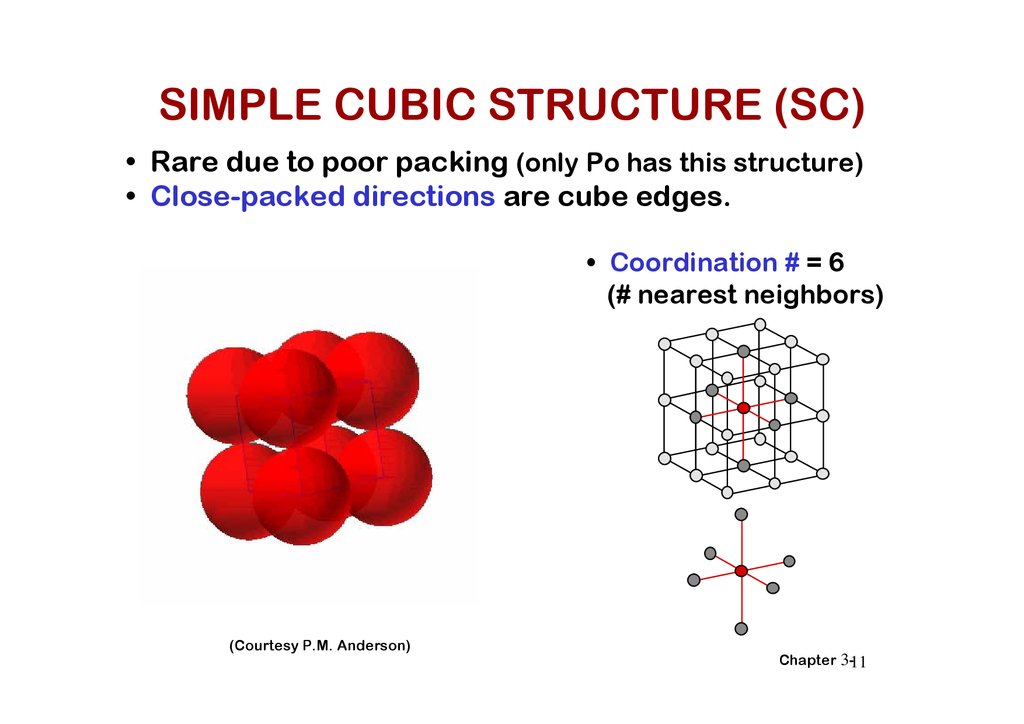
SIMPLE CUBIC STRUCTURE (SC)• Rare due to poor packing (only Po has this structure)
• Close-packed directions are cube edges.
• Coordination # = 6
(# nearest neighbors)
(Courtesy P.M. Anderson)
Chapter 3-11
12.
ATOMIC PACKING FACTORAPF =
Volume of atoms in unit cell*
Volume of unit cell
*assume hard spheres
• APF for a simple cubic structure = 0.52
atoms
unit cell
a
R=0.5a
close-packed directions
contains 8 x 1/8 =
1 atom/unit cell
APF =
volume
atom
4
(0.5a)3
1
3
a3
volume
unit cell
Adapted from Fig. 3.19,
Callister 6e.
Chapter 3-12
13.
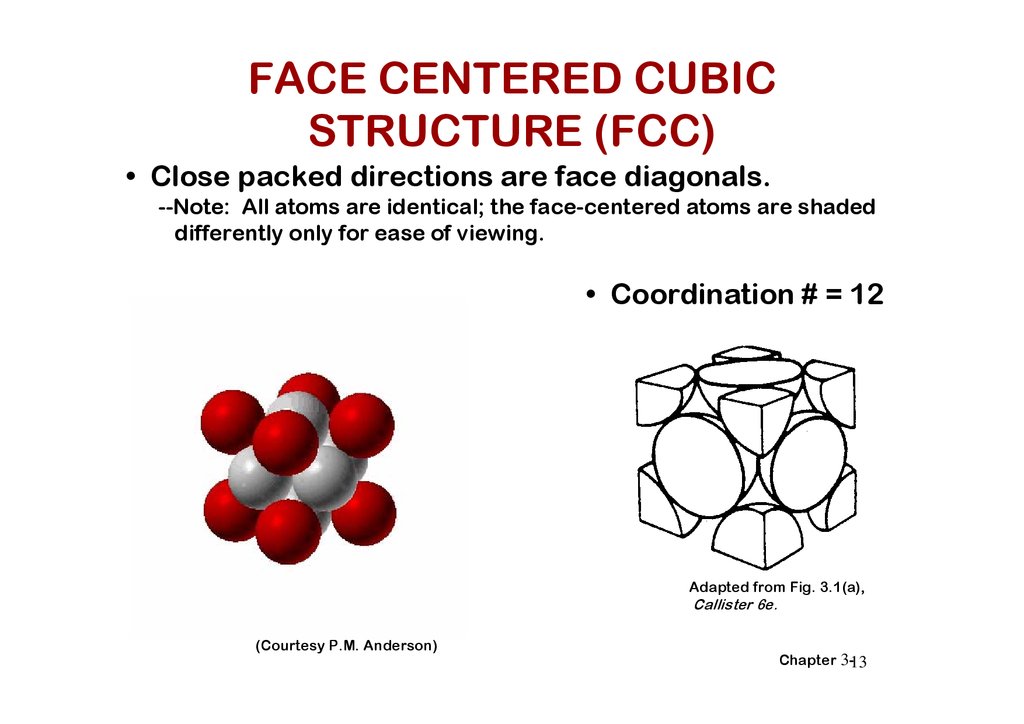
FACE CENTERED CUBICSTRUCTURE (FCC)
• Close packed directions are face diagonals.
--Note: All atoms are identical; the face-centered atoms are shaded
differently only for ease of viewing.
• Coordination # = 12
Adapted from Fig. 3.1(a),
Callister 6e.
(Courtesy P.M. Anderson)
Chapter 3-13
14.
Chapter 3-1415.
ATOMIC PACKING FACTOR: FCC• APF for a FCC structure = 0.74
Close-packed directions:
length = 4R
= 2a
a
Adapted from
Fig. 3.1(a),
Callister 6e.
Unit cell contains:
6 x 1/2 + 8 x 1/8
= 4 atoms/unit cell
atoms
volume
4
3
( 2a/4)
4
unit cell
atom
3
APF =
volume
3
a
unit cell
Chapter 3-15
16.
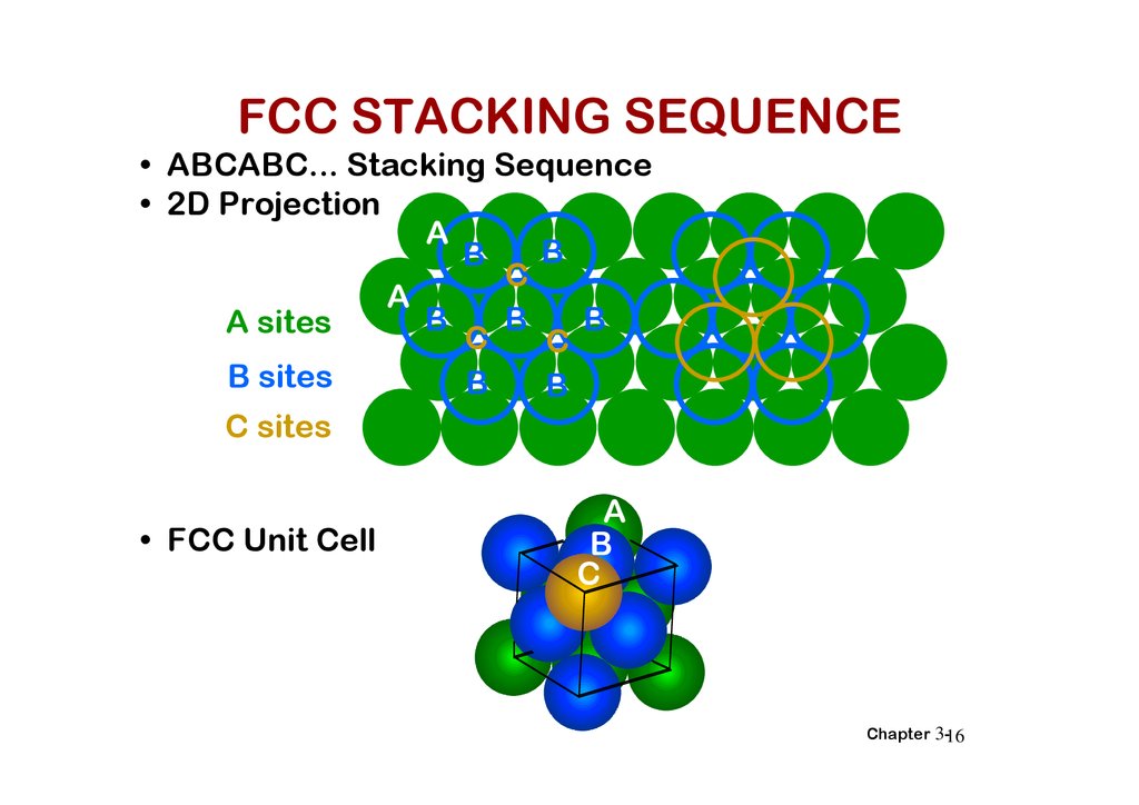
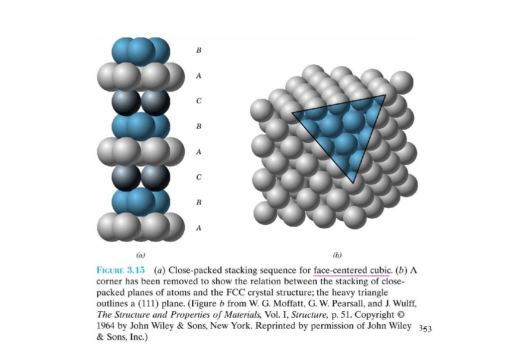
FCC STACKING SEQUENCE• ABCABC... Stacking Sequence
• 2D Projection
A
B
B
C
A
B
B
B
A sites
C
C
B sites
B
B
C sites
• FCC Unit Cell
A
B
C
Chapter 3-16
17.
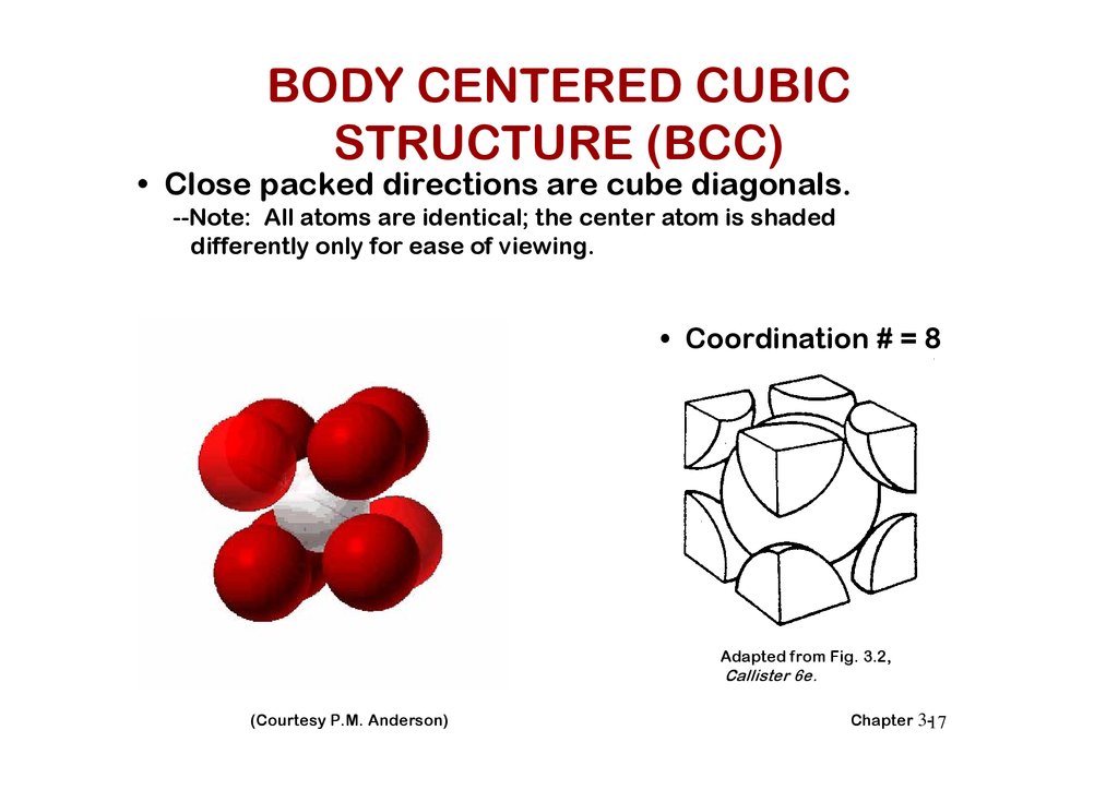
BODY CENTERED CUBICSTRUCTURE (BCC)
• Close packed directions are cube diagonals.
--Note: All atoms are identical; the center atom is shaded
differently only for ease of viewing.
• Coordination # = 8
Adapted from Fig. 3.2,
Callister 6e.
(Courtesy P.M. Anderson)
Chapter 3-17
18.
4Ra
Chapter 3-18
19.
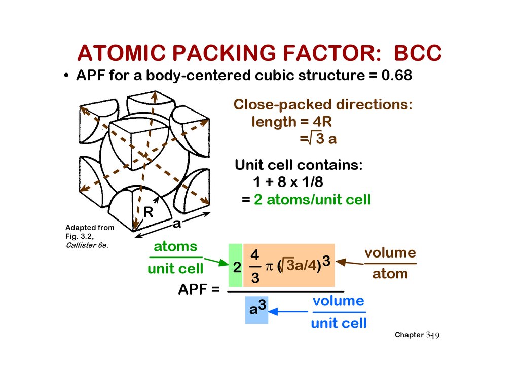
ATOMIC PACKING FACTOR: BCC• APF for a body-centered cubic structure = 0.68
Close-packed directions:
length = 4R
= 3a
R
Adapted from
Fig. 3.2,
Callister 6e.
Unit cell contains:
1 + 8 x 1/8
= 2 atoms/unit cell
a
atoms
volume
4
3
( 3a/4)
2
unit cell
atom
3
APF =
volume
3
a
unit cell
Chapter 3-19
20.
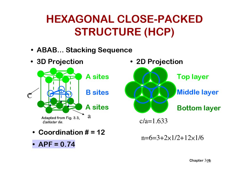
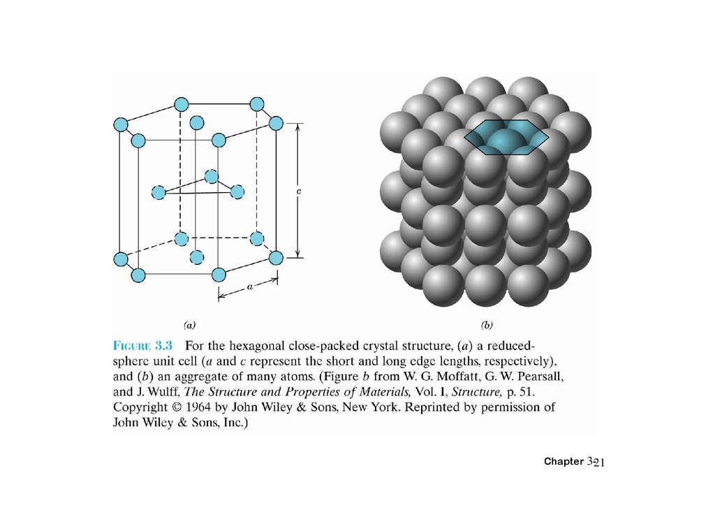
HEXAGONAL CLOSE-PACKEDSTRUCTURE (HCP)
• ABAB... Stacking Sequence
• 3D Projection
C
Adapted from Fig. 3.3,
• 2D Projection
A sites
Top layer
B sites
Middle layer
A sites
a
Bottom layer
Callister 6e.
• Coordination # = 12
• APF = 0.74
c/a=1.633
n=6=3+2×1/2+12×1/6
Chapter 3-20
1
21.
Chapter 3-2122.
Chapter 3-2223.
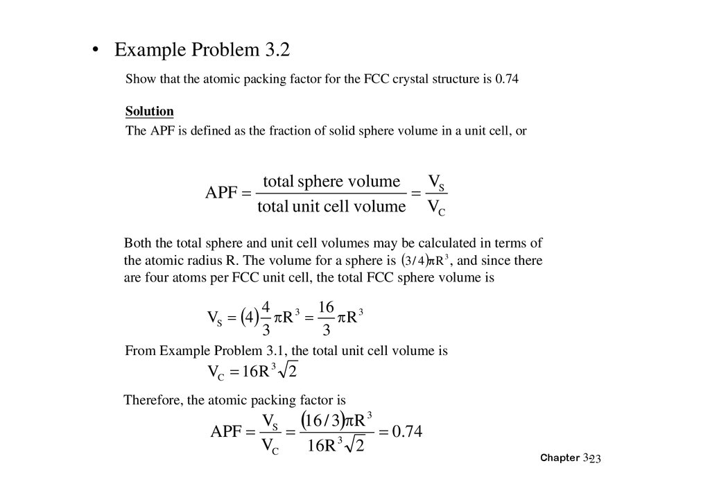
• Example Problem 3.2Show that the atomic packing factor for the FCC crystal structure is 0.74
Solution
The APF is defined as the fraction of solid sphere volume in a unit cell, or
APF
total sphere volume
V
S
total unit cell volume VC
Both the total sphere and unit cell volumes may be calculated in terms of
the atomic radius R. The volume for a sphere is 3 / 4 R 3 , and since there
are four atoms per FCC unit cell, the total FCC sphere volume is
16
4
VS 4 R 3 R 3
3
3
From Example Problem 3.1, the total unit cell volume is
VC 16 R 3 2
Therefore, the atomic packing factor is
VS 16 / 3 R 3
APF
0.74
3
VC
16 R 2
Chapter 3-23
24.
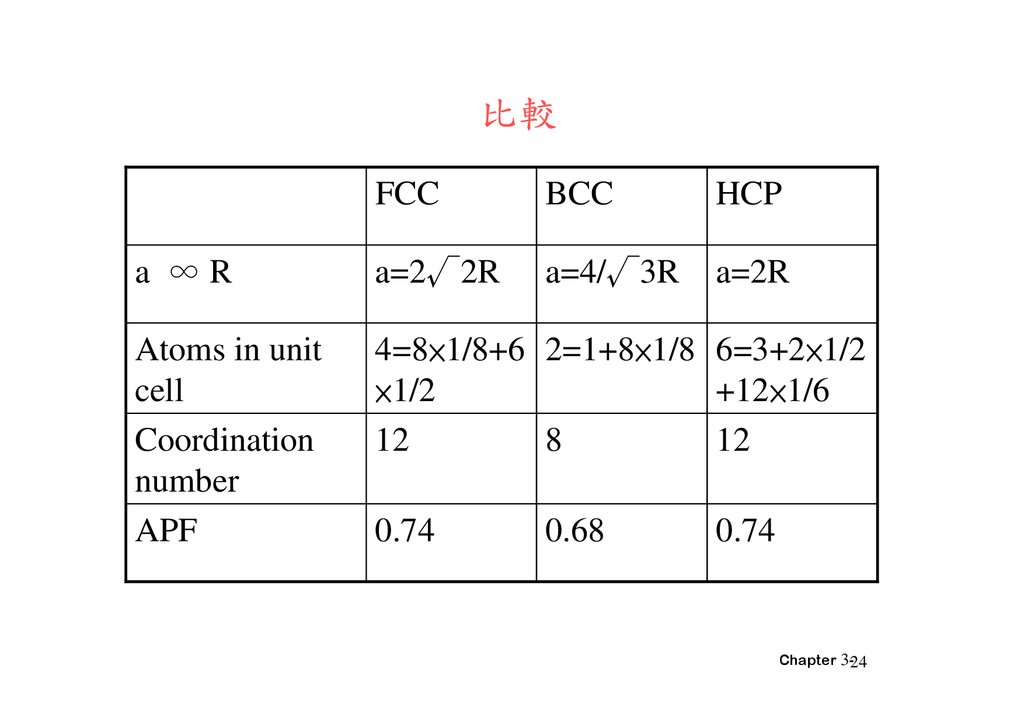
比較FCC
BCC
HCP
a ∞R
a=2√2R
a=4/√3R
a=2R
Atoms in unit
cell
Coordination
number
APF
4=8×1/8+6 2=1+8×1/8 6=3+2×1/2
×1/2
+12×1/6
12
8
12
0.74
0.68
0.74
Chapter 3-24
25.
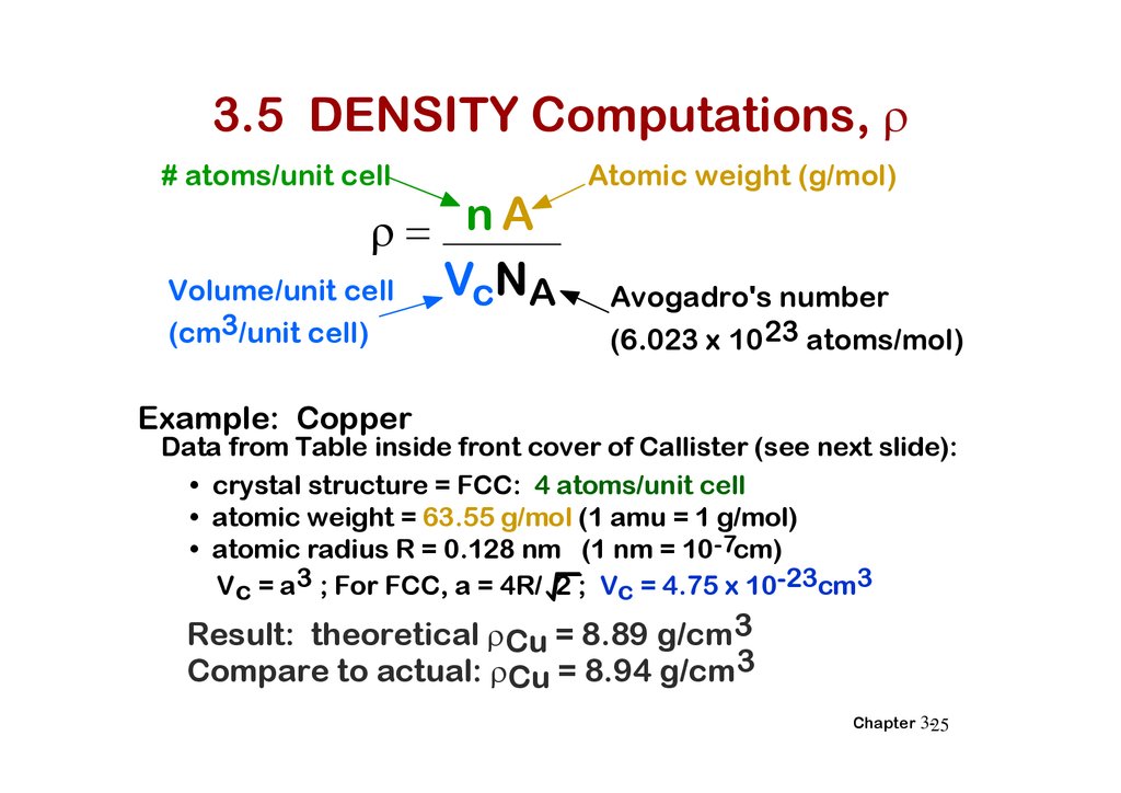
3.5 DENSITY Computations,# atoms/unit cell
nA
VcNA
Volume/unit cell
(cm3/unit cell)
Atomic weight (g/mol)
Avogadro's number
(6.023 x 10 23 atoms/mol)
Example: Copper
Data from Table inside front cover of Callister (see next slide):
• crystal structure = FCC: 4 atoms/unit cell
• atomic weight = 63.55 g/mol (1 amu = 1 g/mol)
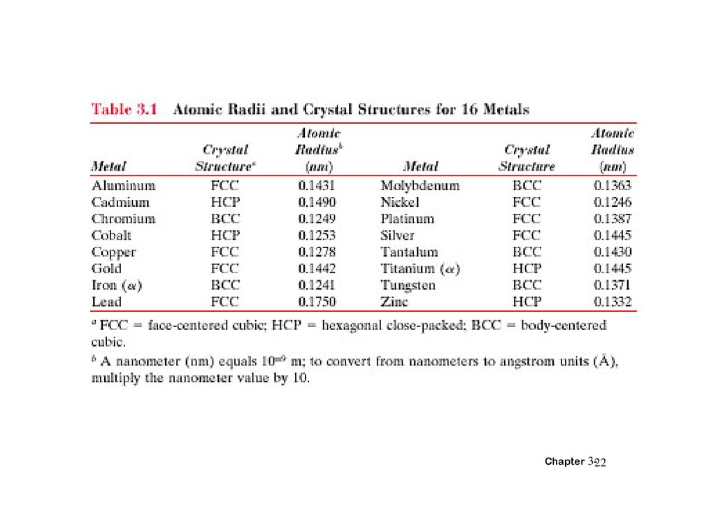
• atomic radius R = 0.128 nm (1 nm = 10-7cm)
Vc = a3 ; For FCC, a = 4R/ 2 ; Vc = 4.75 x 10⁻²³cm3
Result: theoretical Cu = 8.89 g/cm3
Compare to actual: Cu = 8.94 g/cm3
Chapter 3-25
26.
求 FCC 的 密Compare to actual: Cu = 8.94 g/cm3
Chapter 3-26
27.
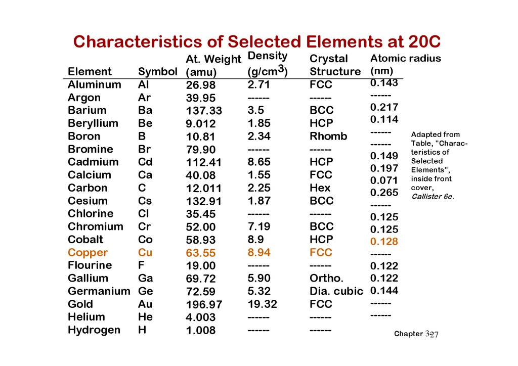
Characteristics of Selected Elements at 20CAt. Weight
Symbol (amu)
Element
Aluminum Al
26.98
Ar
Argon
39.95
Ba
Barium
137.33
Be
Beryllium
9.012
B
Boron
10.81
Br
Bromine
79.90
Cd
Cadmium
112.41
Ca
Calcium
40.08
C
Carbon
12.011
Cs
Cesium
132.91
Cl
Chlorine
35.45
Chromium Cr
52.00
Co
Cobalt
58.93
Cu
Copper
63.55
F
Flourine
19.00
Ga
Gallium
69.72
Germanium Ge
72.59
Au
Gold
196.97
He
Helium
4.003
H
Hydrogen
1.008
Density
(g/cm3)
2.71
-----3.5
1.85
2.34
-----8.65
1.55
2.25
1.87
-----7.19
8.9
8.94
-----5.90
5.32
19.32
-----------
Crystal
Structure
FCC
-----BCC
HCP
Rhomb
-----HCP
FCC
Hex
BCC
-----BCC
HCP
FCC
-----Ortho.
Dia. cubic
FCC
-----------
Atomic radius
(nm)
0.143
-----0.217
0.114
-----Adapted from
Table, "Charac-----of
0.149 teristics
Selected
0.197 Elements",
0.071 inside front
cover,
0.265 Callister 6e.
-----0.125
0.125
0.128
-----0.122
0.122
0.144
----------Chapter 3-27
28.
DENSITIES OF MATERIAL CLASSESmetals? ceramics? polymers
Why?
30
Ceramics have...
(g/cm3)
Metals have...
• close-packing
(metallic bonding)
• large atomic mass
• less dense packing
(covalent bonding)
• often lighter elements
Polymers have...
• poor packing
(often amorphous)
• lighter elements (C,H,O)
Composites have...
• intermediate values
Metals/
Alloys
20
Platinum
Gold, W
Tantalum
10
Silver, Mo
Cu,Ni
Steels
Tin, Zinc
5
4
3
2
1
0.5
0.4
0.3
Titanium
Aluminum
Magnesium
Graphite/
Ceramics/ Polymers
Semicond
Composites/
fibers
Based on data in Table B1, Callister
*GFRE, CFRE, & AFRE are Glass,
Carbon, & Aramid Fiber-Reinforced
Epoxy composites (values based on
60% volume fraction of aligned fibers
in an epoxy matrix).
Zirconia
Al oxide
Diamond
Si nitride
Glass-soda
Concrete
Silicon
Graphite
Glass fibers
PTFE
Silicone
PVC
PET
PC
HDPE, PS
PP, LDPE
GFRE*
Carbon fibers
CFRE*
Aramid fibers
AFRE*
Wood
Data from Table B1, Callister 6e.
Chapter 3-28
29.
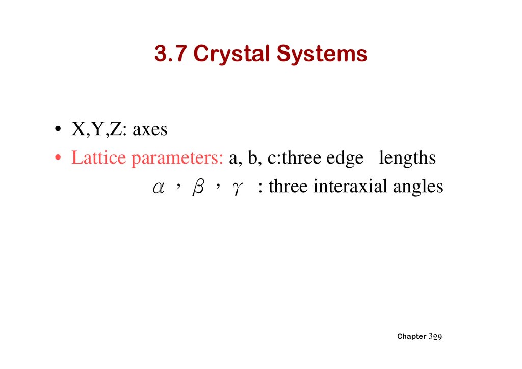
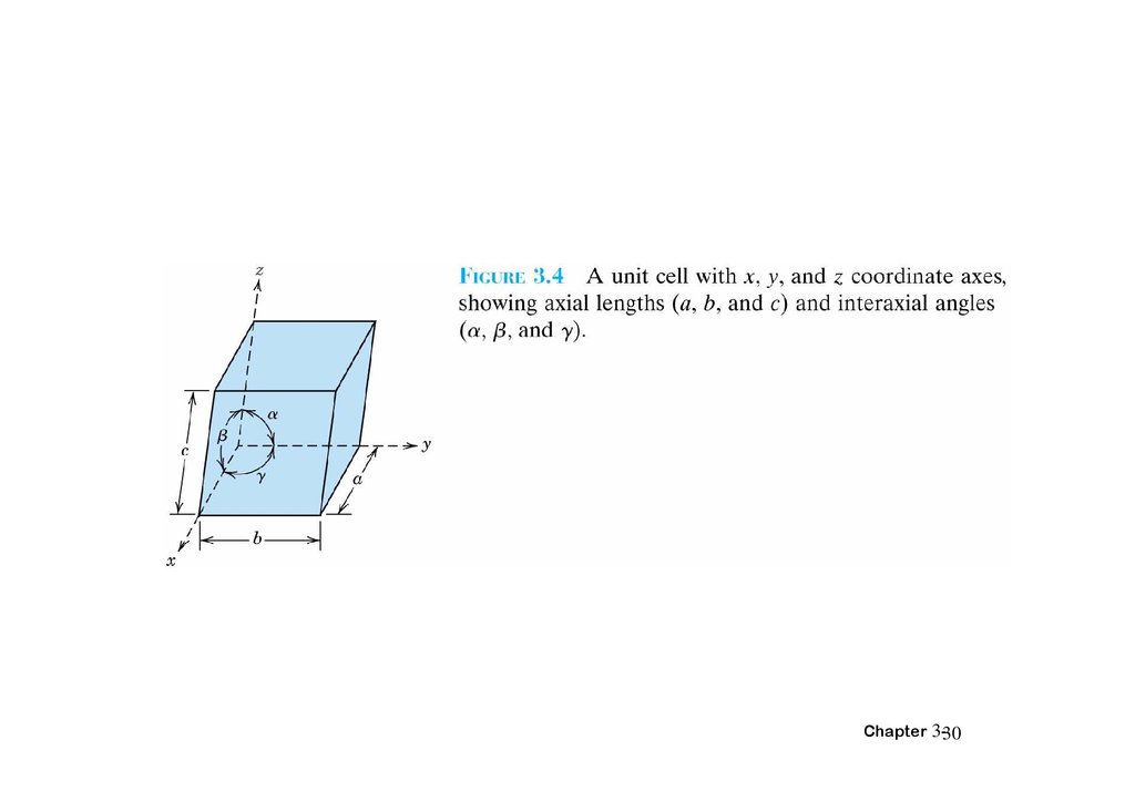
3.7 Crystal Systems• X,Y,Z: axes
• Lattice parameters: a, b, c:three edge lengths
α β γ : three interaxial angles
Chapter 3-29
30.
Chapter 3-3031.
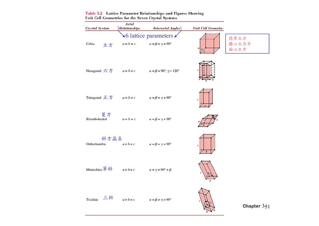
6 lattice parameters方
簡單 方
體心 方
面心 方
方
正方
方
斜方晶系
單斜
三斜
Chapter 3-31
32.
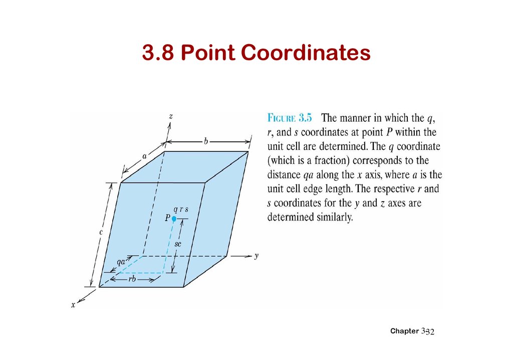
3.8 Point CoordinatesChapter 3-32
33.
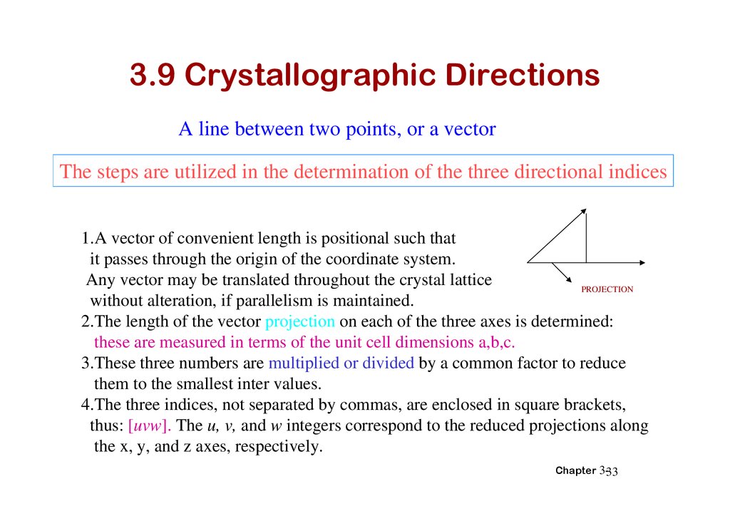
3.9 Crystallographic DirectionsA line between two points, or a vector
The steps are utilized in the determination of the three directional indices
1.A vector of convenient length is positional such that
it passes through the origin of the coordinate system.
Any vector may be translated throughout the crystal lattice
PROJECTION
without alteration, if parallelism is maintained.
2.The length of the vector projection on each of the three axes is determined:
these are measured in terms of the unit cell dimensions a,b,c.
3.These three numbers are multiplied or divided by a common factor to reduce
them to the smallest inter values.
4.The three indices, not separated by commas, are enclosed in square brackets,
thus: [uvw]. The u, v, and w integers correspond to the reduced projections along
the x, y, and z axes, respectively.
Chapter 3-33
34.
Miller indices[direction]
( plane )
Chapter 3-34
35.
Example Problem 3.6Determine the indices for the direction shown in the accompanying figure.
z
Projection on
x axis (a/2)
Projection on
y axis (b)
c
x
This procedure may be summarized as follows:
x
Projections
a/2
Projections (in terms of a, b, and c)
1/2
Reduction
1
Enclosure
y
y
b
1
2
[120]
z
0c
0
0
Chapter 3-35
36.
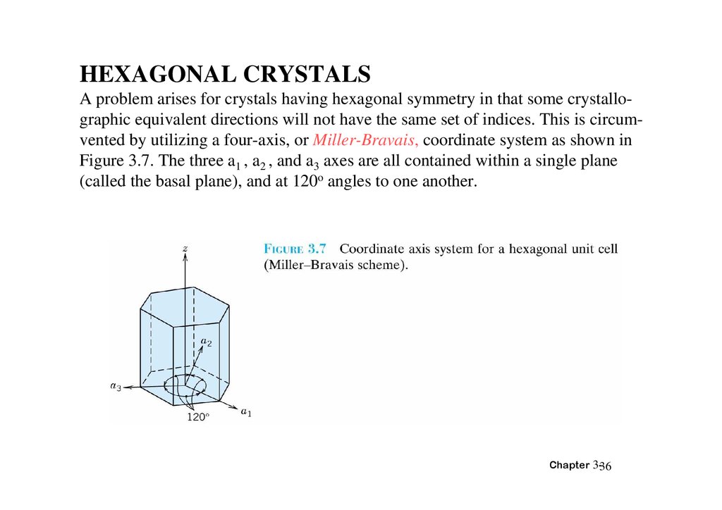
HEXAGONAL CRYSTALSA problem arises for crystals having hexagonal symmetry in that some crystallographic equivalent directions will not have the same set of indices. This is circumvented by utilizing a four-axis, or Miller-Bravais, coordinate system as shown in
Figure 3.7. The three a1 , a2 , and a3 axes are all contained within a single plane
(called the basal plane), and at 120o angles to one another.
Chapter 3-36
37.
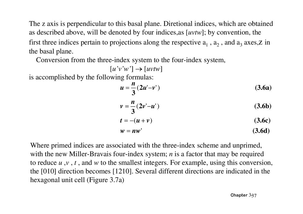
The z axis is perpendicular to this basal plane. Diretional indices, which are obtainedas described above, will be denoted by four indices,as [uvtw]; by convention, the
first three indices pertain to projections along the respective a1 , a2 , and a3 axes,z in
the basal plane.
Conversion from the three-index system to the four-index system,
[u’v’w’] [uvtw]
is accomplished by the following formulas:
n
(3.6a)
u ( 2u' v ' )
3
n
(3.6b)
v ( 2v ' u' )
3
(3.6c)
t ( u v )
(3.6d)
w nw'
Where primed indices are associated with the three-index scheme and unprimed,
with the new Miller-Bravais four-index system; n is a factor that may be required
to reduce u ,v , t , and w to the smallest integers. For example, using this conversion,
the [010] direction becomes [1210]. Several different directions are indicated in the
hexagonal unit cell (Figure 3.7a)
Chapter 3-37
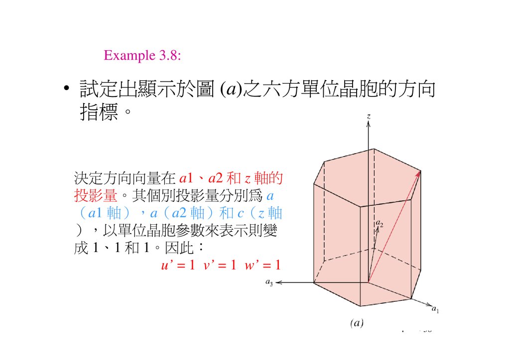
38.
Example 3.8:• 試定出顯示於圖 (a)之 方單位晶胞的方向
指標。
決定方向向 在 a1、a2 和 z 軸的
投影 。其個別投影 分別為 a
a1 軸 a a2 軸 和 c z 軸
以單位晶胞 表示則變
成 1、1 和 1。因此
u’ = 1 v’ = 1 w’ = 1
Chapter 3-38
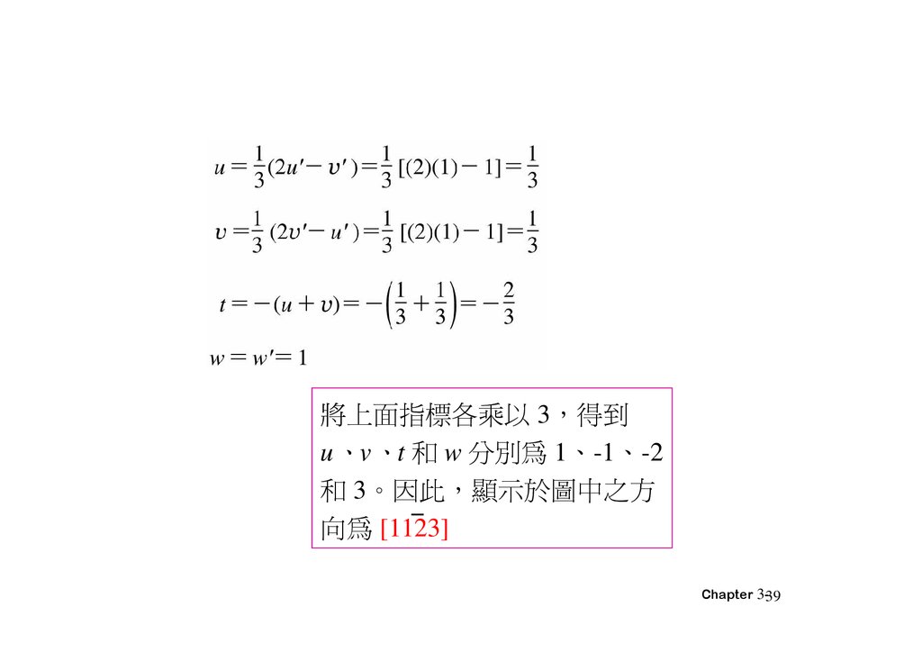
39.
將上面指標各乘以 3 得到u、v、t 和 w 分別為 1、-1、-2
和 3。因此 顯示於圖中之方
向為 [1123]
Chapter 3-39
40.
截距:1∞1倒 =101=(hkl)
i=-(h+k)=-(1+0)=-1
(hkil)= 1011
Chapter 3-40
41.
3.10 Crystallographic PlanesThe procedure determine the h, k, l Miller index numbers
1.If the plane passes through the selected origin, either another parallel plane must be
constructed within the unit cell by an appropriate translation, or a new origin must be
established at the corner of another unit cell.
2.At this point the crystallographic plane either intersects or parallels each of the three
axes; the length of the planar intercept for each axis is determined in terms of the lattice
parameters a, b, and c.
3.The reciprocals of these numbers are taken. A plane that parallels an axis may be
considered to have an infinite intercept, and, therefore, a zero index.
4.If necessary, these three numbers are changed to the set of smallest integers by
multiplication or division by a common factor.
5.Finally, the integer indices, not separated by commas, are enclosed within parentheses,
thus: (hkl).
Chapter 3-41
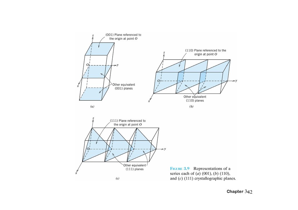
42.
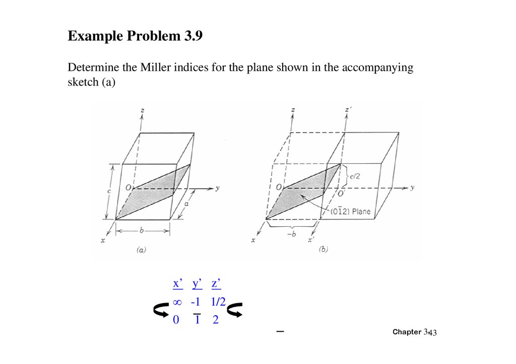
Chapter 3-4243.
Example Problem 3.9Determine the Miller indices for the plane shown in the accompanying
sketch (a)
x’ y’ z’
-1 1/2
0 1 2
Chapter 3-43
44.
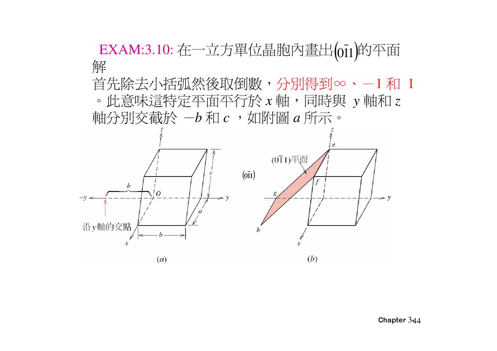
EXAM:3.10: 在一 方單位晶胞內畫出 011 的平面解
首先除去小括弧然後取倒 分別得到∞、 1 和 1
。此意味這特定平面平 於 x 軸 同時與 y 軸和 z
軸分別交截於 b 和 c 如附圖 a 所示。
011
Chapter 3-44
45.
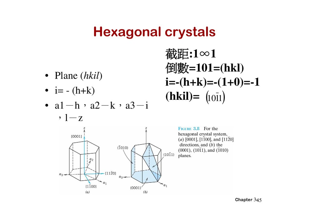
Hexagonal crystals• Plane (hkil)
• i= - (h+k)
• a1 h a2 k a3 i
l z
截距:1∞1
倒 =101=(hkl)
i=-(h+k)=-(1+0)=-1
(hkil)= 1011
Chapter 3-45
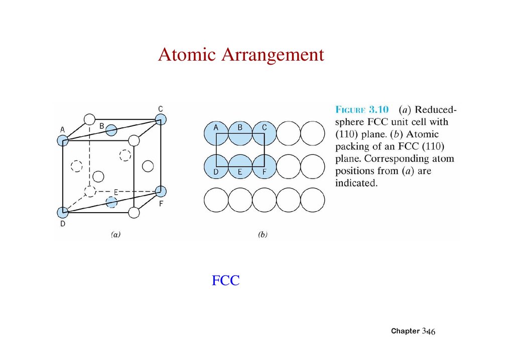
46.
Atomic ArrangementFCC
Chapter 3-46
47.
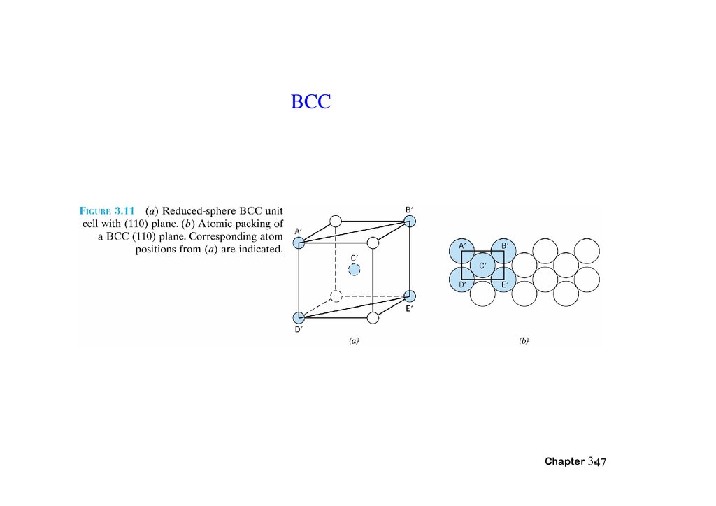
BCCChapter 3-47
48.
3.11 Linear and Planar Densities• LD:linear density
• LD=number of atom centered on direction
vector/length of direction vector
Chapter 3-48
49.
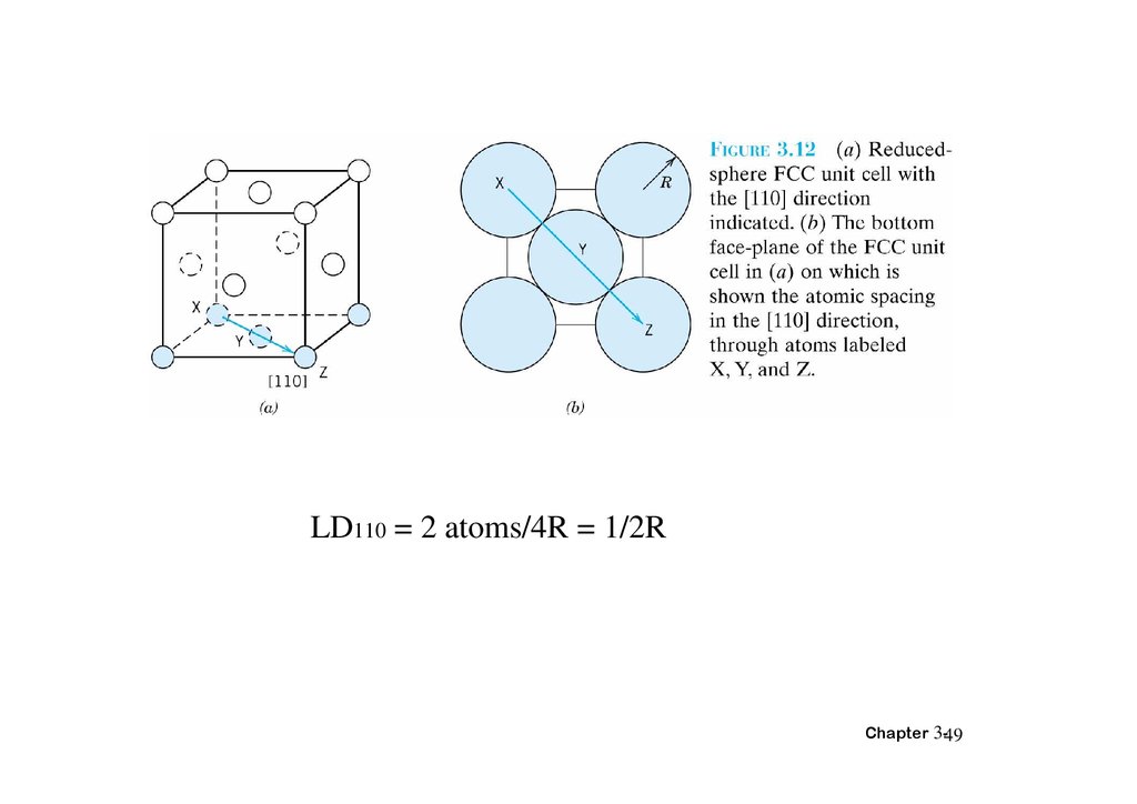
LD110 = 2 atoms/4R = 1/2RChapter 3-49
50.
PD = Planar density• PD = number of atoms centered on a plane/area
of plane
2
• PD110 = 2atoms/(4R) ×(2√2R)= 1/4R √2
(Fig3.10b)
Chapter 3-50
51.
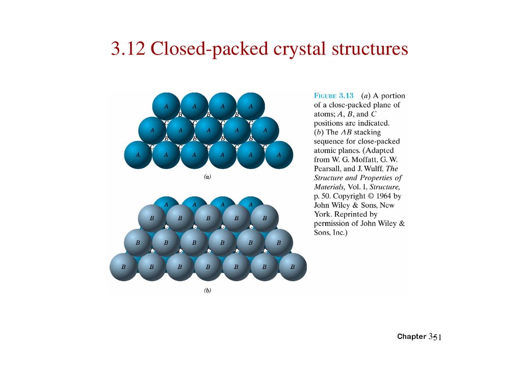
3.12 Closed-packed crystal structuresChapter 3-51
52.
Chapter 3-5253.
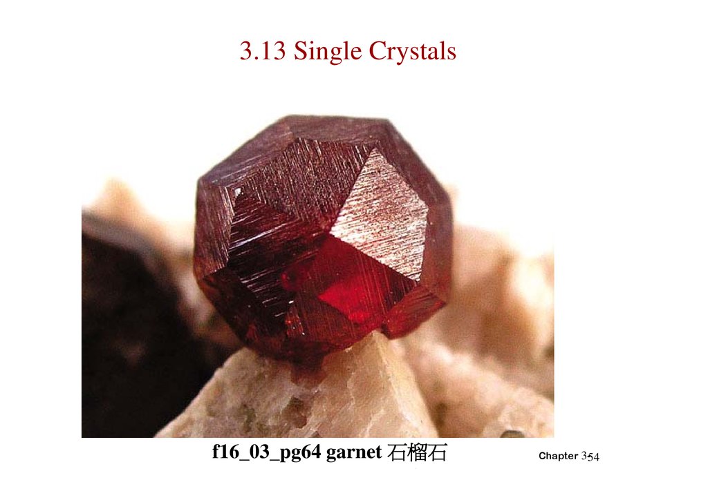
Chapter 3-5354.
3.13 Single Crystalsf16_03_pg64 garnet 石榴石
Chapter 3-54
55.
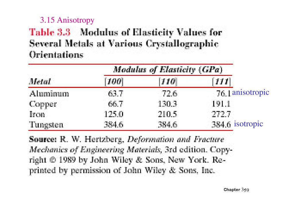
SINGLE VS POLYCRYSTALS• Single Crystals
E (diagonal) = 273 GPa
Data from Table 3.3,
Callister 6e.
(Source of data is
R.W. Hertzberg,
-Properties vary with
direction: anisotropic.
-Example: the modulus
of elasticity (E) in BCC iron:
• Polycrystals
-Properties may/may not
vary with direction.
-If grains are randomly
oriented: isotropic.
(Epoly iron = 210 GPa)
-If grains are textured,
anisotropic.
Deformation and
Fracture Mechanics of
Engineering Materials,
3rd ed., John Wiley
and Sons, 1989.)
E (edge) = 125 GPa
200 m
Adapted from Fig.
4.12(b), Callister 6e.
(Fig. 4.12(b) is
courtesy of L.C. Smith
and C. Brady, the
National Bureau of
Standards,
Washington, DC [now
the National Institute
of Standards and
Technology,
Gaithersburg, MD].)
Chapter 3-55
56.
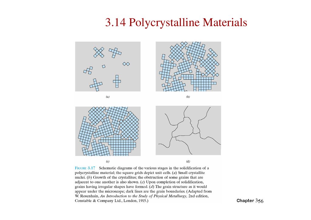
3.14 Polycrystalline MaterialsChapter 3-56
57.
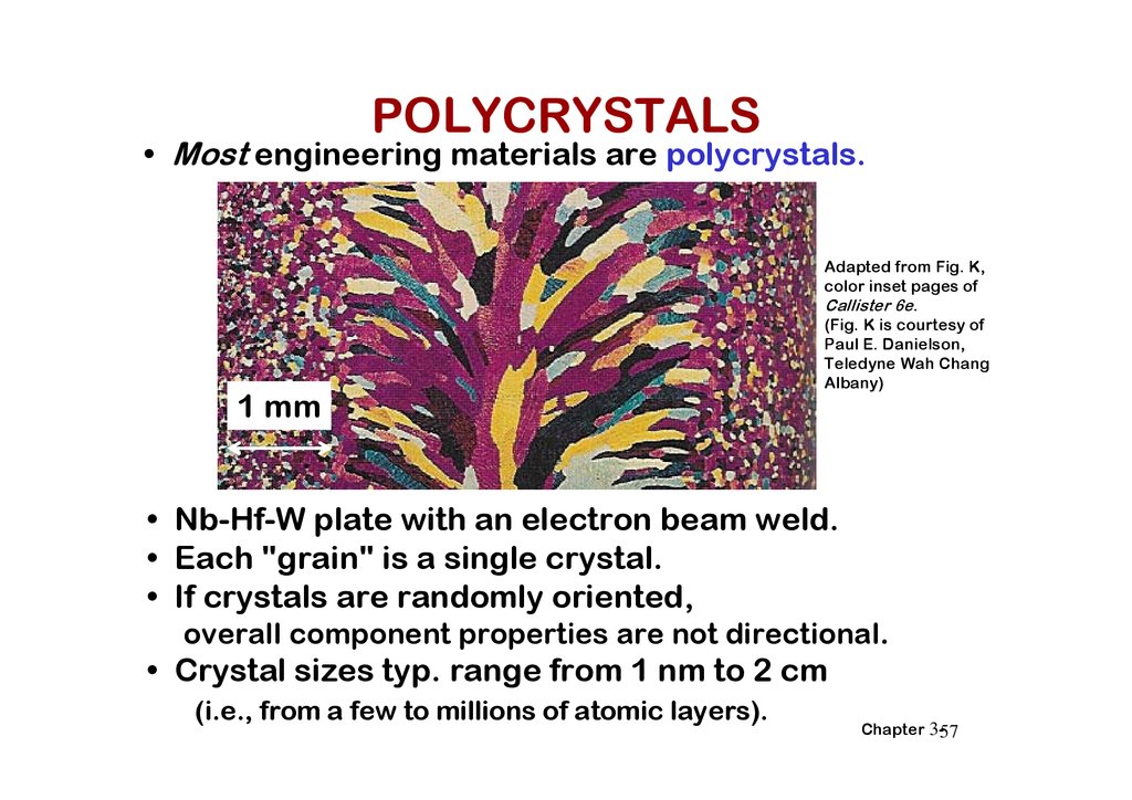
POLYCRYSTALS• Most engineering materials are polycrystals.
1 mm
Adapted from Fig. K,
color inset pages of
Callister 6e.
(Fig. K is courtesy of
Paul E. Danielson,
Teledyne Wah Chang
Albany)
• Nb-Hf-W plate with an electron beam weld.
• Each "grain" is a single crystal.
• If crystals are randomly oriented,
overall component properties are not directional.
• Crystal sizes typ. range from 1 nm to 2 cm
(i.e., from a few to millions of atomic layers).
Chapter 3-57
58.
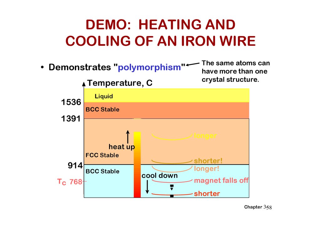
DEMO: HEATING ANDCOOLING OF AN IRON WIRE
• Demonstrates "polymorphism"
Temperature, C
1536
The same atoms can
have more than one
crystal structure.
Liquid
BCC Stable
1391
longer
heat up
FCC Stable
914
Tc 768
BCC Stable
cool down
shorter!
longer!
magnet falls off
shorter
Chapter 3-58
59.
3.15 Anisotropyanisotropic
isotropic
Chapter 3-59
60.
3.16 X-ray diffraction: Determination ofcrystal structures
Acrobat 文件
Chapter 3-60
61.
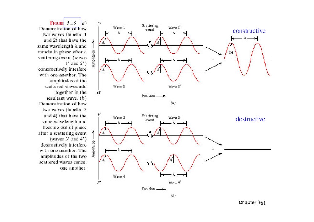
3.18constructive
destructive
Chapter 3-61
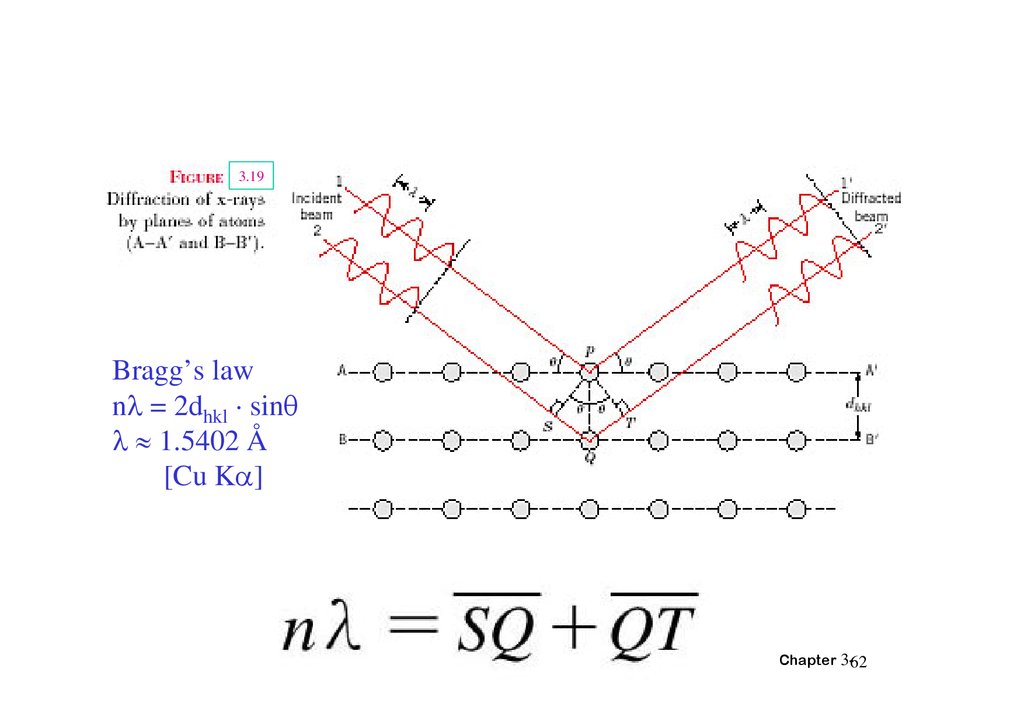
62.
3.19Bragg’s law
n = 2dhkl · sin
1.5402 Å
[Cu K ]
Chapter 3-62
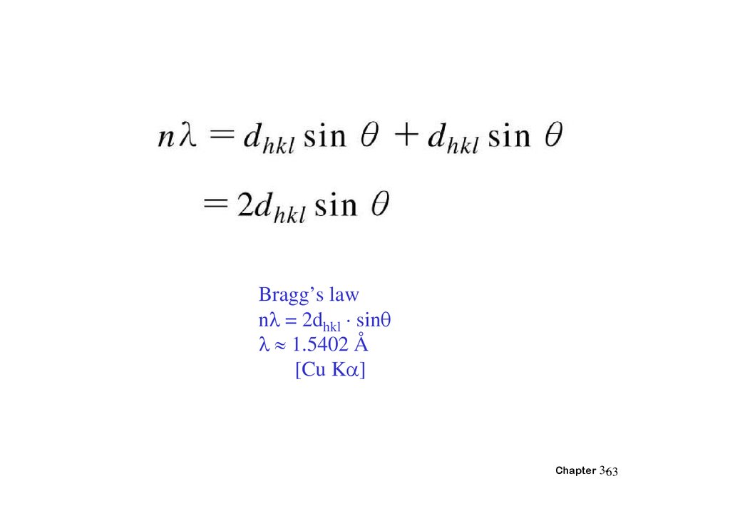
63.
Bragg’s lawn = 2dhkl · sin
1.5402 Å
[Cu K ]
Chapter 3-63
64.
X-光繞射和布 格定方體:
Chapter 3-64
65.
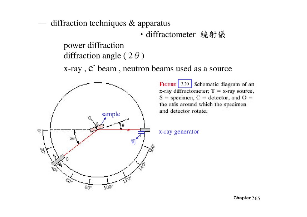
— diffraction techniques & apparatus‧diffractometer 繞射儀
power diffraction
diffraction angle ( 2θ)
-
x-ray , e beam , neutron beams used as a source
3.20
sample
x-ray generator
閘
Chapter 3-65
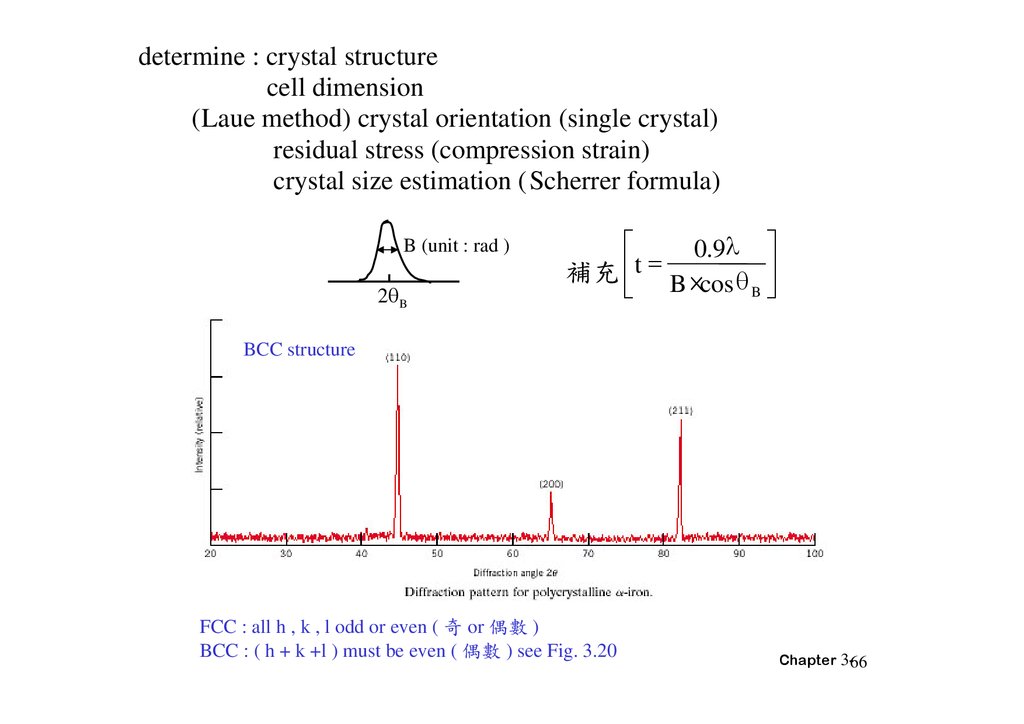
66.
determine : crystal structurecell dimension
(Laue method) crystal orientation (single crystal)
residual stress (compression strain)
crystal size estimation (Scherrer formula)
B (unit : rad )
2 B
0.9
補充 t B ×cos
B
BCC structure
FCC : all h , k , l odd or even ( 奇 or 偶 )
BCC : ( h + k +l ) must be even ( 偶 ) see Fig. 3.20
Chapter 3-66
67.
Figure3.21 Diffraction pattern for powdered lead.Chapter 3-67
68.
題 3.12 球平面間距 與繞射角對 BCC 鐵而言 計算(220)平面組之 (a)平面間距 與 (b)繞
射角。Fe 的晶格 為 0.2866nm。同時 假設所使用之單
光 射波長為 0.1790nm 且反射級 為 1。
解
(a) 平面間距dnkl之值可用 3.16 式決定 同時 a = 2.866nm
且h = 2 k = 2 及 l = 0 由於我們考慮的是 (220) 平面 因此
Chapter 3-68
P. 83
69.
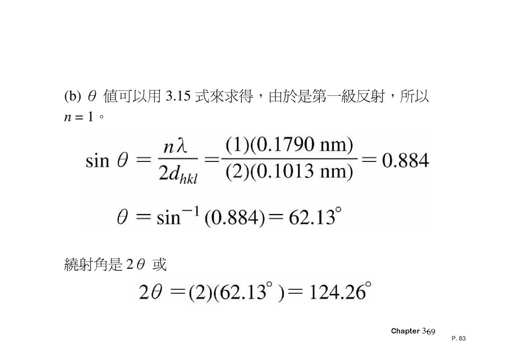
(b) θ 值可以用 3.15 式 求得 由於是第一級反射 所以n = 1。
繞射角是 2θ 或
Chapter 3-69
P. 83
70.
example ()‧Fe(BCC) a=0.2866 , h,k,l = (2,1,1)
d hkl
a
2 1 1
2
2
2
0.117nm
λ=0.1542nm
‧Cu Kα1 x-ray
n‧λ = 2‧dhkl‧sinθhkl n=1
1 0.1542
sin 2 0.117 0.659
∴ 2 2 sin 1 82.44 o
Chapter 3-70
71.
3.17 Noncrystalline Solids3.22
Chapter 3-71
72.
SUMMARY• Atoms may assemble into crystalline or
amorphous structures.
• We can predict the density of a material,
provided we know the atomic weight, atomic
radius, and crystal geometry (e.g., FCC,
BCC, HCP).
• Material properties generally vary with single
crystal orientation (i.e., they are anisotropic),
but properties are generally non-directional
(i.e., they are isotropic) in polycrystals with
randomly oriented grains.
Chapter 3-72