


 mechanics
Similar presentations:


")


 - Technical Highlights")
How To - Understanding Clutches
1. How To – Understanding Clutches
How To – Understanding ClutchesThis presentation deals with the PT Tech 12” Dry, 12” Wet and 14” Wet clutches, Desch clutch and has the
following appendices:
Appendix A:
Appendix B:
Appendix C:
Appendix C:
Ref #: tdoc00061
Rev: 3
Date: 24-11-2017
Aut: N McClelland
Troubleshooting using the PT Tech Display
SPN FMI codes
Machine Types Vs Controller types
Desch clutch
1
2.
How To – Understanding ClutchesSafety Alert Symbol
This is the safety alert symbol. It is used in this manual to alert you to potential personal injury hazards. Obey all
safety messages that follow this symbol to avoid possible injury or death.
Before you start
The information included in this document is intended for experienced personnel familiar with this type of
equipment.
Only trained and competent personnel should perform the work outlined in this document.
If there are any questions regarding the information provided or the application of the provided information, please
contact, techtraining@terex.com
Operation and maintenance of the machine must be done in accordance with the instructions in the operation
manual for the machine.
Review the safety, operation, and maintenance sections of the operation manual prior to performing this work.
Ref #: tdoc00061
Rev: 3
Date: 24-11-2017
Aut: N McClelland
2
3.
How To – Understanding ClutchesLockout / Tagout
WHEN CARRYING OUT MAINTENANCE OR ADJUSTMENT THE FOLLOWING
LOCKOUT / TAGOUT PROCEDURE MUST BE FOLLOWED:
1.
2.
3.
4.
5.
6.
7.
Ensure the machine is empty prior to shut down.
Disengage each machine component (e.g. conveyors, etc.) using the control levers.
Note: Turning off all machine components at once causes a pressure spike in the hydraulic circuit.
A slight pause between disengaging each component can prevent this spike from taking place.
Turn components off in the order:
A. Component one (e.g. Feeder)
B. Component two (e.g. Side Conveyor or Main Conveyor)
C. Component three (e.g. Crushing Chamber or Screenbox/Fines Conveyor)
D. Component four (e.g. Product Conveyor or RH/LH Side Conveyor)
Switch off engine and remove ignition key. Carry the key with you.
Engage emergency stop.
Use padlock to secure machine isolator at powerunit to prevent restart.
Place appropriate maintenance warning sign.
NEVER WORK ALONE
Ref #: tdoc00061
Rev: 3
Date: 24-11-2017
Aut: N McClelland
3
4.
How To – Understanding ClutchesHydraulic System Safety
Fluid escaping under pressure can penetrate skin and result in death or serious injury.
Relieve pressure before disconnecting hydraulic lines.
Stay clear of leaks and pin holes. Use a piece of cardboard or wood to search for leaks. Do not use you hands to check for
leaks.
Fluid injected into skin must be surgically removed within a few hours by a doctor familiar with this type of injury, or
gangrene will result.
High pressure fluid is present in operational hydraulic systems.
Fluids under pressure are hazardous and can cause serious injury or death.
Always consider gravity before carrying out any work on a hydraulic machine (stored energy risk).
Any part of a hydraulic circuit that is supporting a load can remain pressurized (stored energy risk).
Even after the system has been shut down, attempting to remove a hydraulic line or component that is supporting a load
can result in a sudden release of pressure and/or uncontrolled movement of the load, causing serious personal injury
and/or property damage.
Modifications to hydraulic systems require written approval from Terex.
Do not make repairs or adjustments to any hydraulic system unless you are competent or working under competent
supervision.
If in doubt, consult the technical support department.
Ref #: tdoc00061
Rev: 3
Date: 24-11-2017
Aut: N McClelland
4
5.
How To – Understanding ClutchesStay Safe
ALWAYS use gloves or barrier cream.
ALWAYS Lockout / Tagout machine prior to carrying out any work.
ALWAYS immediately clean up any spilled hydraulic oil with correct absorbent material.
NEVER work alone.
NEVER use your hands to check for leaks (skin injection risk).
REMEMBER: Hydraulic systems use fluids under high pressure which can cause major injury or death.
REMEMBER: STAY SAFE, STAY ALIVE
Ref #: tdoc00061
Rev: 3
Date: 24-11-2017
Aut: N McClelland
5
6.
How To – Understanding ClutchesPersonal Protective Equipment (PPE)
Your personal safety is the number one priority. Before performing any task or procedure you should wear the
following personal protective equipment as required:
Safety glasses
Steel toed safety boots
Hearing defenders
Hard hat
Gloves (heat resistant gloves if performing hot work)
Tight fitting overalls (fire retardant overalls if performing hot work)
High visibility vest
Full body harness (if working at height)
Ref #: tdoc00061
Rev: 3
Date: 24-11-2017
Aut: N McClelland
6
7.
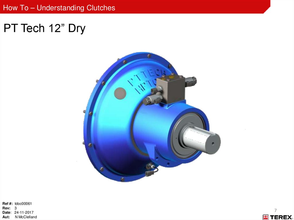
How To – Understanding ClutchesPT Tech 12” Dry
Ref #: tdoc00061
Rev: 3
Date: 24-11-2017
Aut: N McClelland
7
8.
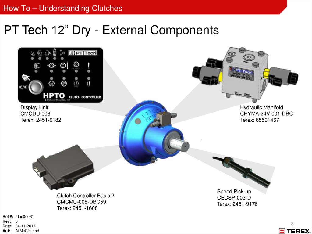
How To – Understanding ClutchesPT Tech 12” Dry - External Components
Display Unit
CMCDU-008
Terex: 2451-9182
Clutch Controller Basic 2
CMCMU-008-DBC59
Terex: 2451-1608
Ref #: tdoc00061
Rev: 3
Date: 24-11-2017
Aut: N McClelland
Hydraulic Manifold
CHYMA-24V-001-DBC
Terex: 65501467
Speed Pick-up
CECSP-003-D
Terex: 2451-9176
8
9.
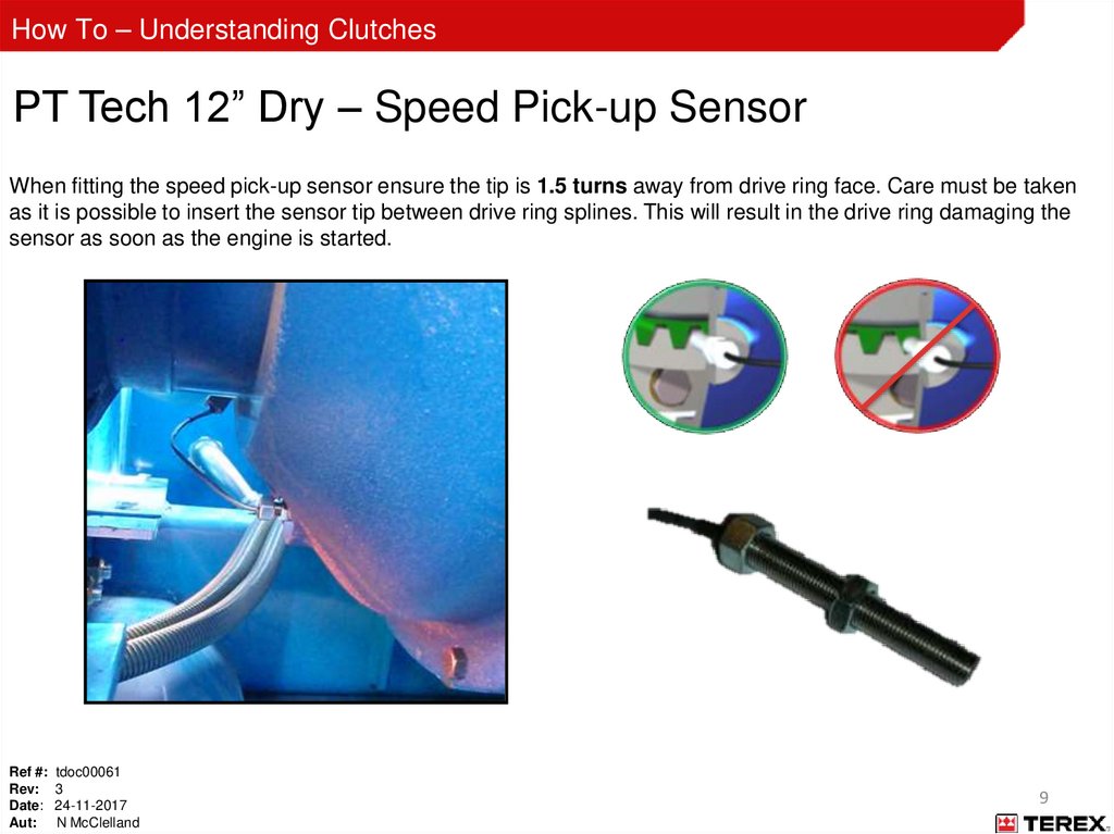
How To – Understanding ClutchesPT Tech 12” Dry – Speed Pick-up Sensor
When fitting the speed pick-up sensor ensure the tip is 1.5 turns away from drive ring face. Care must be taken
as it is possible to insert the sensor tip between drive ring splines. This will result in the drive ring damaging the
sensor as soon as the engine is started.
Ref #: tdoc00061
Rev: 3
Date: 24-11-2017
Aut: N McClelland
9
10.
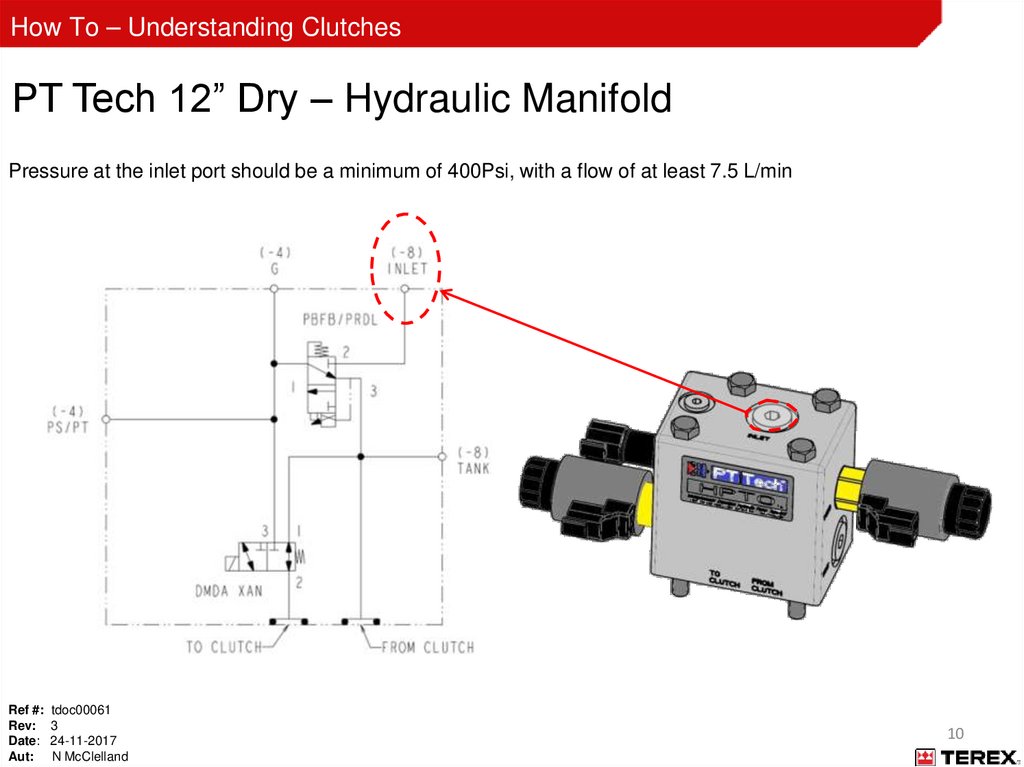
How To – Understanding ClutchesPT Tech 12” Dry – Hydraulic Manifold
Pressure at the inlet port should be a minimum of 400Psi, with a flow of at least 7.5 L/min
Ref #: tdoc00061
Rev: 3
Date: 24-11-2017
Aut: N McClelland
10
11.
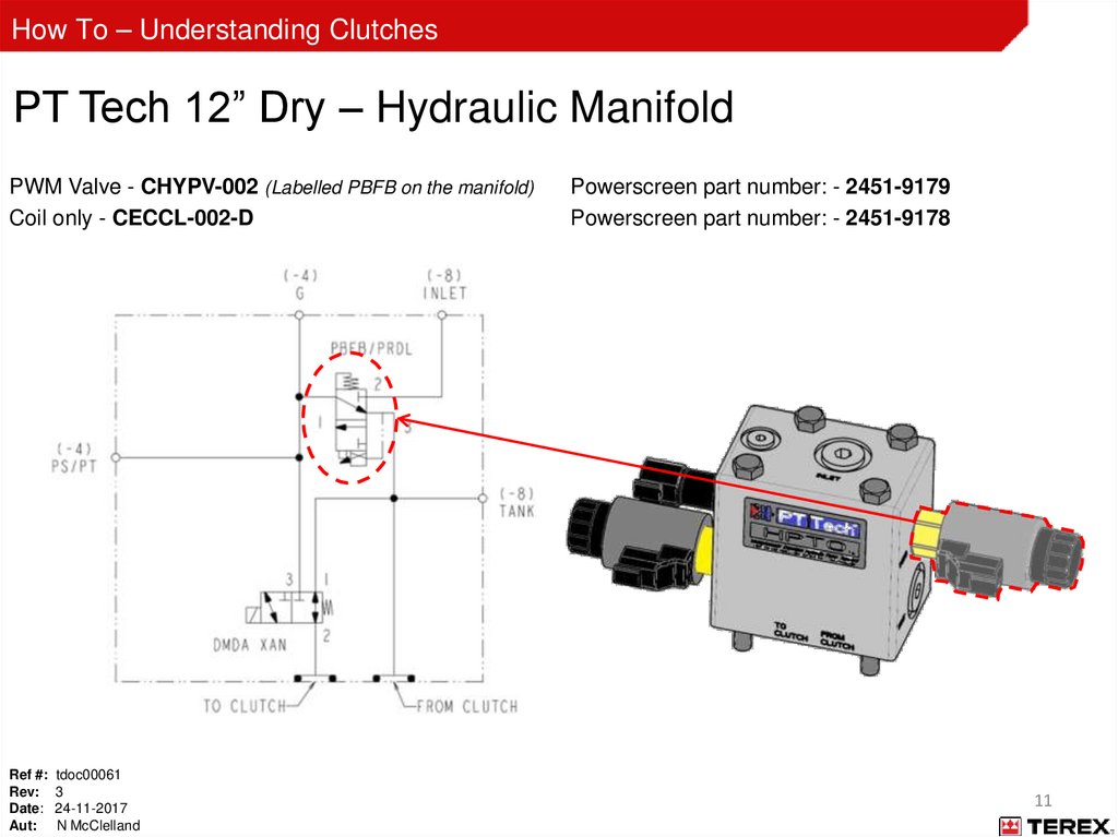
How To – Understanding ClutchesPT Tech 12” Dry – Hydraulic Manifold
PWM Valve - CHYPV-002 (Labelled PBFB on the manifold)
Coil only - CECCL-002-D
Ref #: tdoc00061
Rev: 3
Date: 24-11-2017
Aut: N McClelland
Powerscreen part number: - 2451-9179
Powerscreen part number: - 2451-9178
11
12.
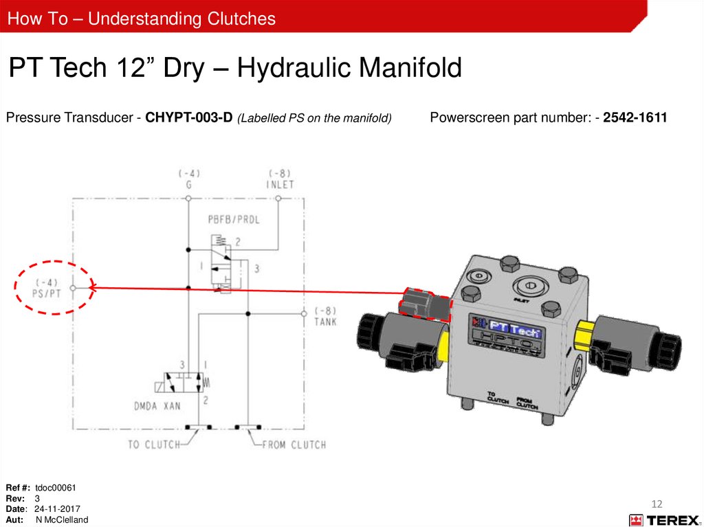
How To – Understanding ClutchesPT Tech 12” Dry – Hydraulic Manifold
Pressure Transducer - CHYPT-003-D (Labelled PS on the manifold)
Ref #: tdoc00061
Rev: 3
Date: 24-11-2017
Aut: N McClelland
Powerscreen part number: - 2542-1611
12
13.
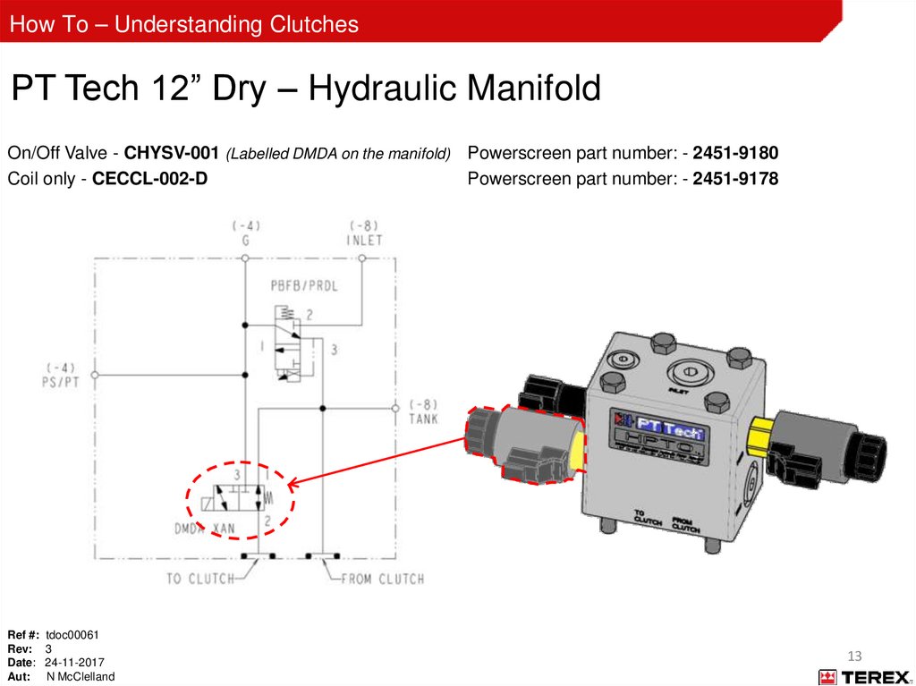
How To – Understanding ClutchesPT Tech 12” Dry – Hydraulic Manifold
On/Off Valve - CHYSV-001 (Labelled DMDA on the manifold) Powerscreen part number: - 2451-9180
Coil only - CECCL-002-D
Powerscreen part number: - 2451-9178
Ref #: tdoc00061
Rev: 3
Date: 24-11-2017
Aut: N McClelland
13
14.
How To – Understanding ClutchesPT Tech 12” Dry – Hydraulic Manifold
Test Point (Labelled G on the manifold)
Tank Drain Line
5 PSI maximum
Ref #: tdoc00061
Rev: 3
Date: 24-11-2017
Aut: N McClelland
14
15.
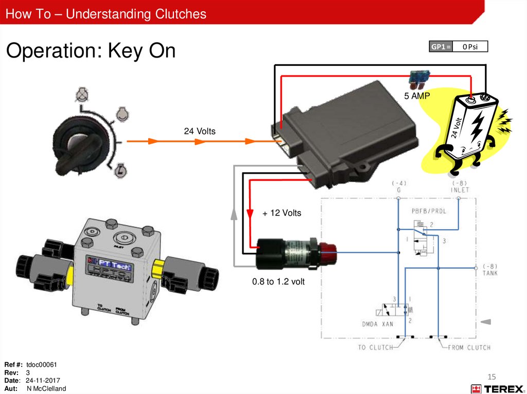
How To – Understanding ClutchesOperation: Key On
GP1 =
0 Psi
5 AMP
24 Volts
+ 12 Volts
0.8 to 1.2 volt
Ref #: tdoc00061
Rev: 3
Date: 24-11-2017
Aut: N McClelland
15
16.
How To – Understanding ClutchesEngine Running
GP1 = 225 Psi
5 AMP
24 Volts
400 PSI
Minimum
+ 12 Volts
225PSI
4 Volts
PWM Coil
0 PSI
Ref #: tdoc00061
Rev: 3
Date: 24-11-2017
Aut: N McClelland
16
17.
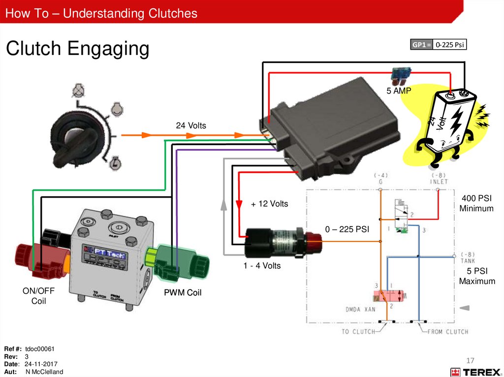
How To – Understanding ClutchesClutch Engaging
GP1 = 0-225 Psi
5 AMP
24 Volts
400 PSI
Minimum
+ 12 Volts
0 – 225 PSI
1 - 4 Volts
ON/OFF
Coil
Ref #: tdoc00061
Rev: 3
Date: 24-11-2017
Aut: N McClelland
5 PSI
Maximum
PWM Coil
17
18.
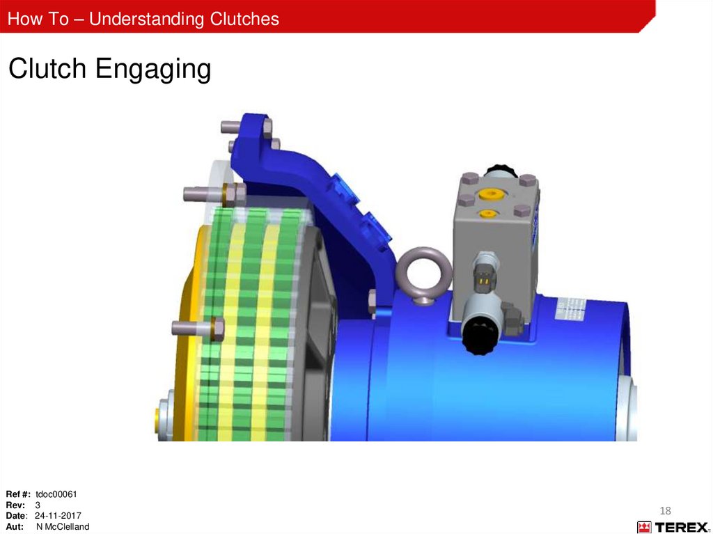
How To – Understanding ClutchesClutch Engaging
Ref #: tdoc00061
Rev: 3
Date: 24-11-2017
Aut: N McClelland
18
19.
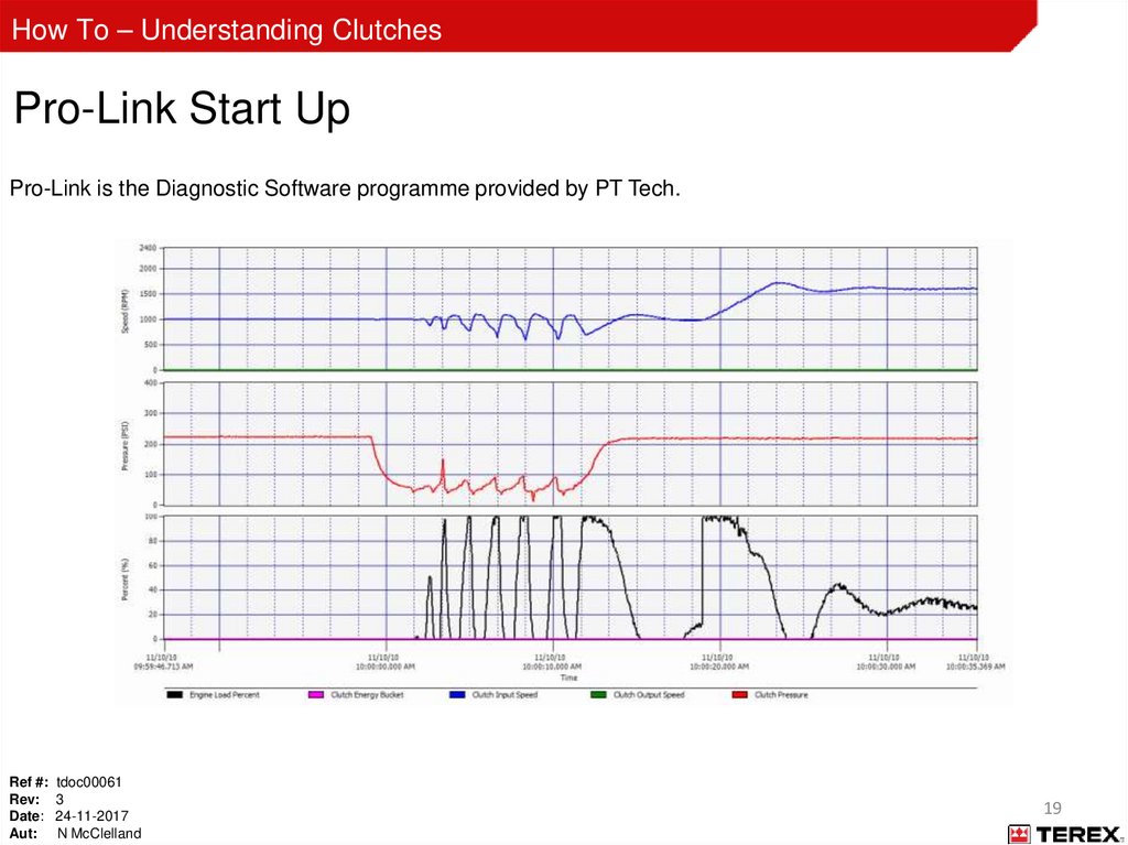
How To – Understanding ClutchesPro-Link Start Up
Pro-Link is the Diagnostic Software programme provided by PT Tech.
Ref #: tdoc00061
Rev: 3
Date: 24-11-2017
Aut: N McClelland
19
20.
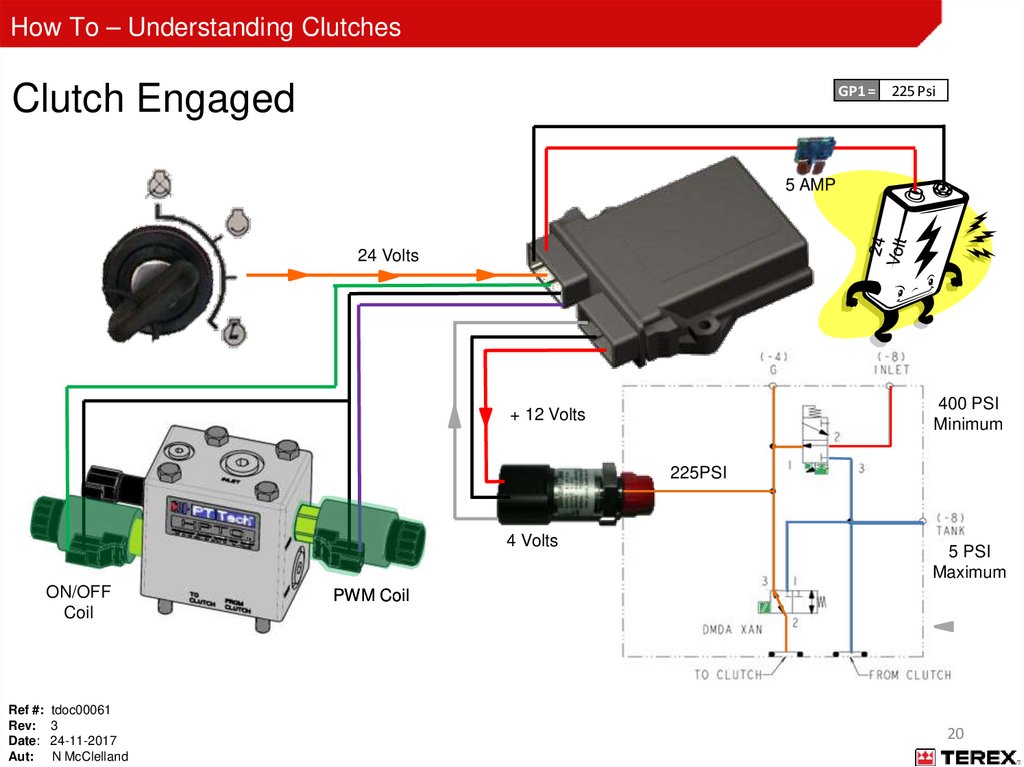
How To – Understanding ClutchesClutch Engaged
GP1 = 225 Psi
5 AMP
24 Volts
400 PSI
Minimum
+ 12 Volts
225PSI
4 Volts
ON/OFF
Coil
Ref #: tdoc00061
Rev: 3
Date: 24-11-2017
Aut: N McClelland
5 PSI
Maximum
PWM Coil
20
21.
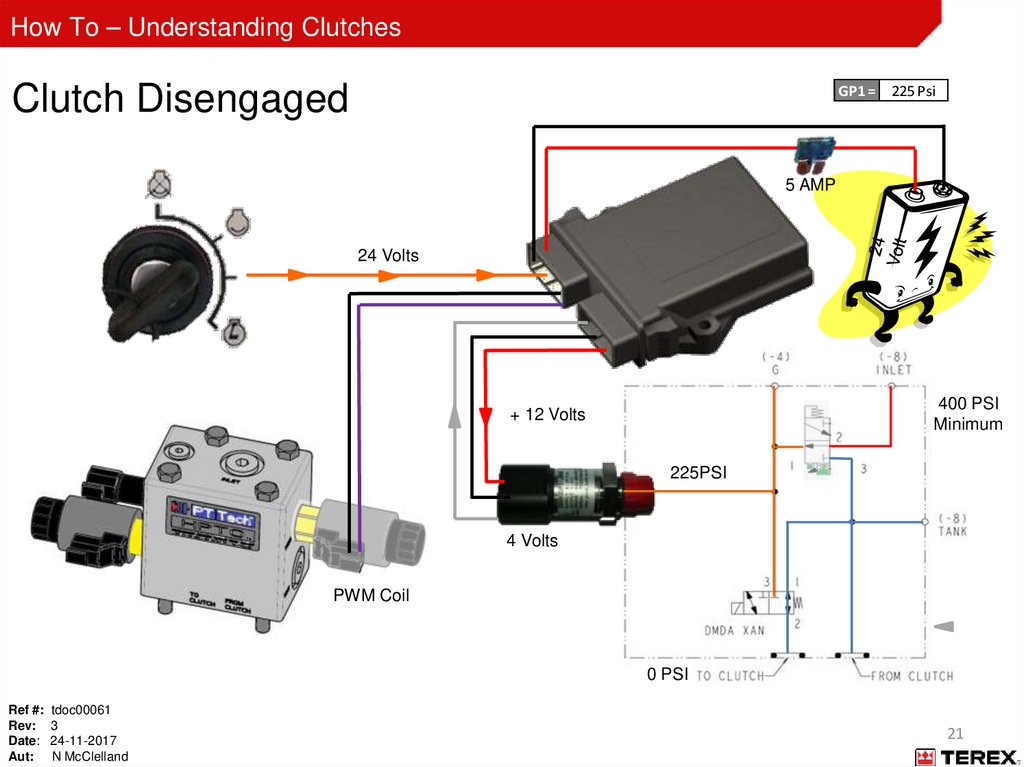
How To – Understanding ClutchesClutch Disengaged
GP1 = 225 Psi
5 AMP
24 Volts
400 PSI
Minimum
+ 12 Volts
225PSI
4 Volts
PWM Coil
0 PSI
Ref #: tdoc00061
Rev: 3
Date: 24-11-2017
Aut: N McClelland
21
22.
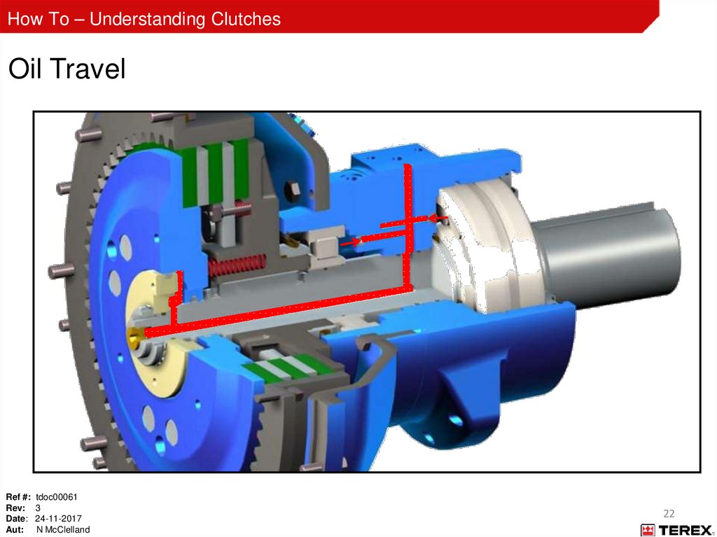
How To – Understanding ClutchesOil Travel
Ref #: tdoc00061
Rev: 3
Date: 24-11-2017
Aut: N McClelland
22
23.
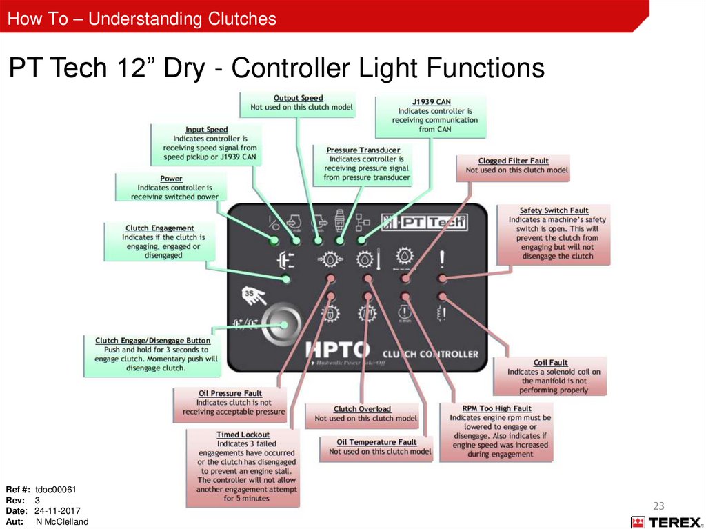
How To – Understanding ClutchesPT Tech 12” Dry - Controller Light Functions
Ref #: tdoc00061
Rev: 3
Date: 24-11-2017
Aut: N McClelland
23
24.
How To – Understanding ClutchesPT Tech 12” Dry - Controller Operating Sequence
Key On:
• Power light ON
• Pressure transducer light ON
• J1939 CAN light ON (if connected)
Ref #: tdoc00061
Rev: 3
Date: 24-11-2017
Aut: N McClelland
24
25.
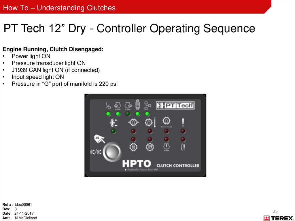
How To – Understanding ClutchesPT Tech 12” Dry - Controller Operating Sequence
Engine Running, Clutch Disengaged:
• Power light ON
• Pressure transducer light ON
• J1939 CAN light ON (if connected)
• Input speed light ON
• Pressure in “G” port of manifold is 220 psi
Ref #: tdoc00061
Rev: 3
Date: 24-11-2017
Aut: N McClelland
25
26.
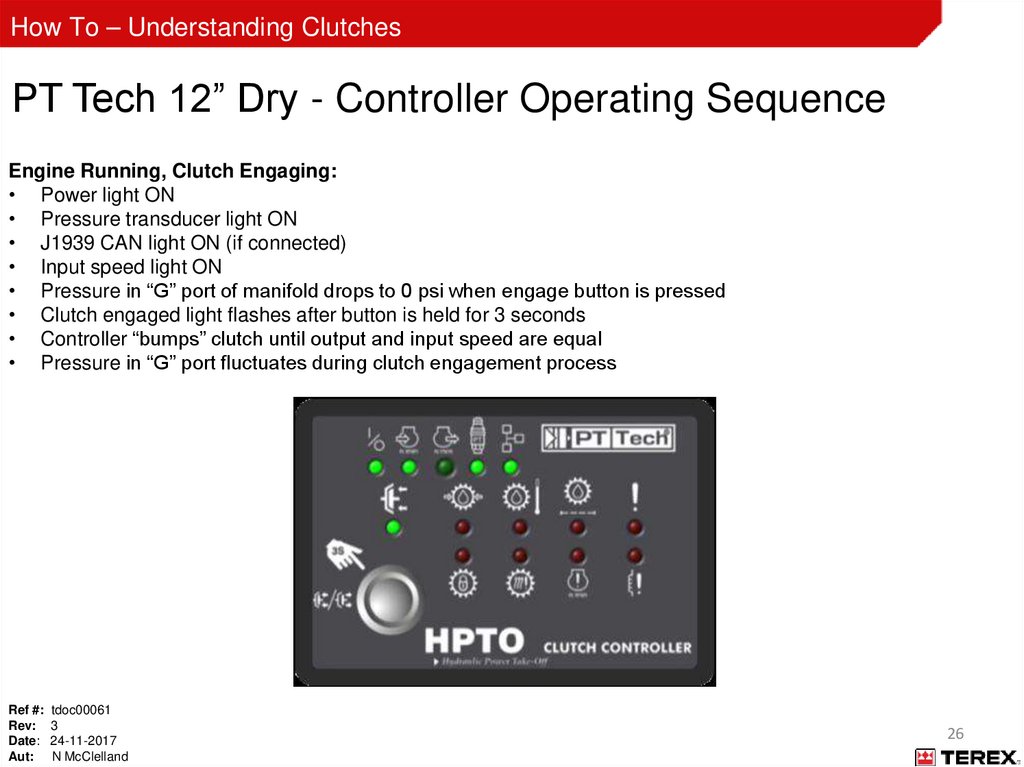
How To – Understanding ClutchesPT Tech 12” Dry - Controller Operating Sequence
Engine Running, Clutch Engaging:
• Power light ON
• Pressure transducer light ON
• J1939 CAN light ON (if connected)
• Input speed light ON
• Pressure in “G” port of manifold drops to 0 psi when engage button is pressed
• Clutch engaged light flashes after button is held for 3 seconds
• Controller “bumps” clutch until output and input speed are equal
• Pressure in “G” port fluctuates during clutch engagement process
Ref #: tdoc00061
Rev: 3
Date: 24-11-2017
Aut: N McClelland
26
27.
How To – Understanding ClutchesPT Tech 12” Dry - Controller Operating Sequence
Engine Running, Clutch Engaged:
• Power light ON
• Pressure transducer light ON
• J1939 CAN light ON (if connected)
• Input speed light ON
• Pressure in “G” port of manifold is 220 psi
Ref #: tdoc00061
Rev: 3
Date: 24-11-2017
Aut: N McClelland
27
28.
How To – Understanding ClutchesClutch Controller Basic 2 (CMCMU-008DBC 59) (SP1)
The SP1 denotation at the end of the part number shows that this clutch is for the 1300 Maxtrak.
This Controller disables the PT Tech display’s on/off button.
See “Appendix C” for machine details on controller types
Ref #: tdoc00061
Rev: 3
Date: 24-11-2017
Aut: N McClelland
28
29.
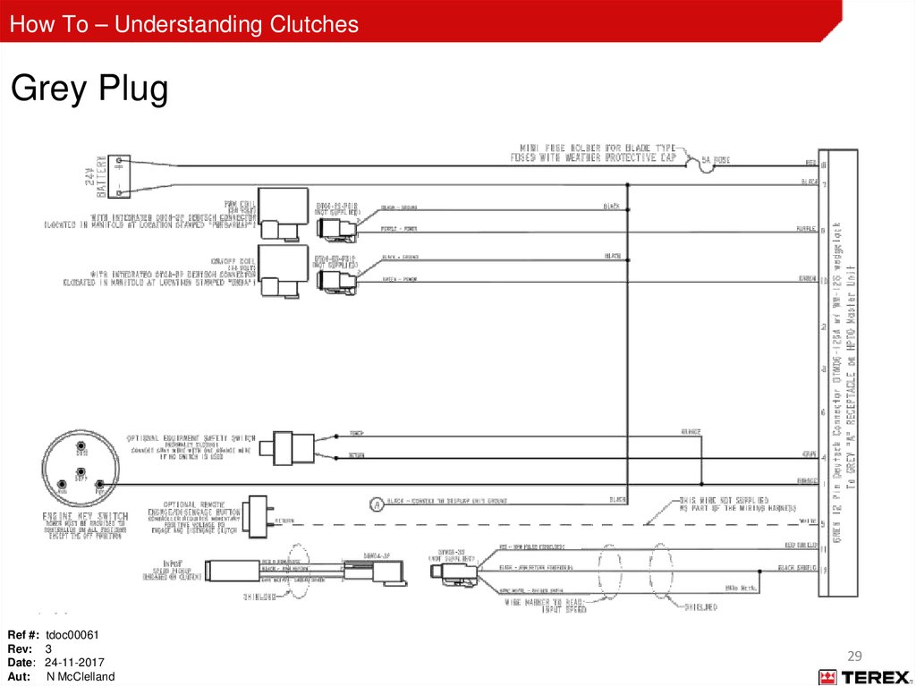
How To – Understanding ClutchesGrey Plug
Ref #: tdoc00061
Rev: 3
Date: 24-11-2017
Aut: N McClelland
29
30.
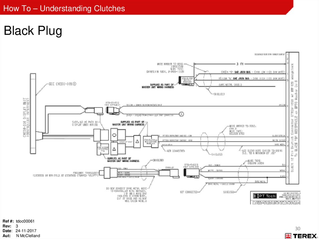
How To – Understanding ClutchesBlack Plug
Ref #: tdoc00061
Rev: 3
Date: 24-11-2017
Aut: N McClelland
30
31.
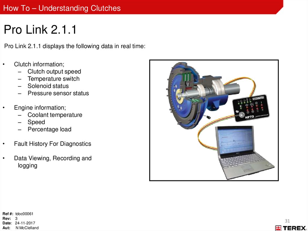
How To – Understanding ClutchesPro Link 2.1.1
Pro Link 2.1.1 displays the following data in real time:
Clutch information;
– Clutch output speed
– Temperature switch
– Solenoid status
– Pressure sensor status
Engine information;
– Coolant temperature
– Speed
– Percentage load
Fault History For Diagnostics
Data Viewing, Recording and
logging
Ref #: tdoc00061
Rev: 3
Date: 24-11-2017
Aut: N McClelland
31
32.
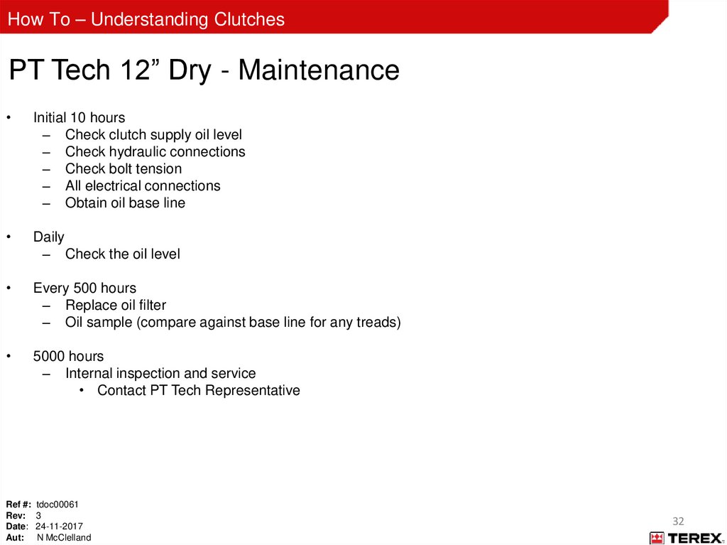
How To – Understanding ClutchesPT Tech 12” Dry - Maintenance
Initial 10 hours
– Check clutch supply oil level
– Check hydraulic connections
– Check bolt tension
– All electrical connections
– Obtain oil base line
Daily
– Check the oil level
Every 500 hours
– Replace oil filter
– Oil sample (compare against base line for any treads)
5000 hours
– Internal inspection and service
• Contact PT Tech Representative
Ref #: tdoc00061
Rev: 3
Date: 24-11-2017
Aut: N McClelland
32
33.
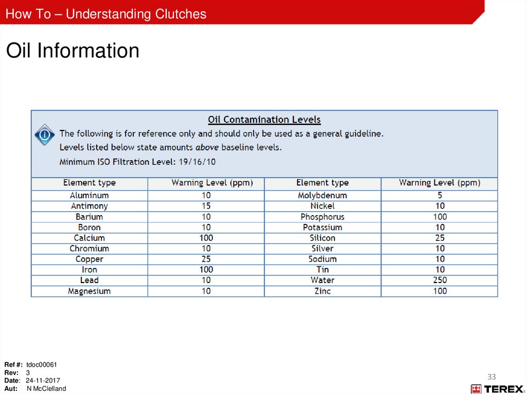
How To – Understanding ClutchesOil Information
Ref #: tdoc00061
Rev: 3
Date: 24-11-2017
Aut: N McClelland
33
34.
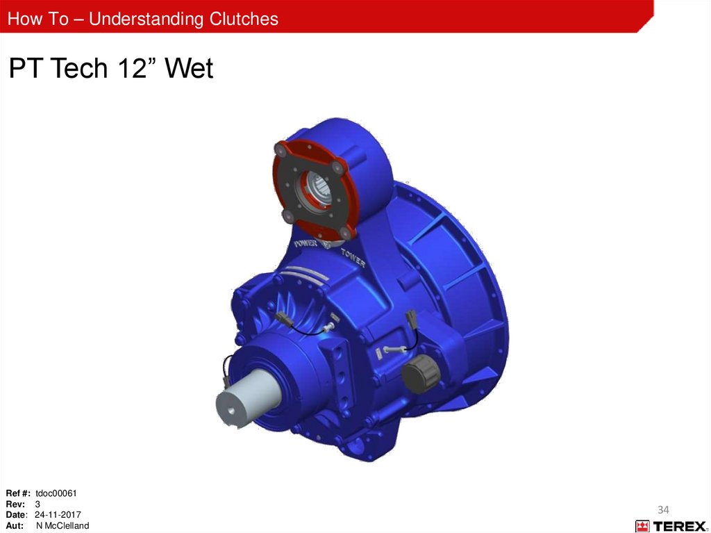
How To – Understanding ClutchesPT Tech 12” Wet
Ref #: tdoc00061
Rev: 3
Date: 24-11-2017
Aut: N McClelland
34
35.
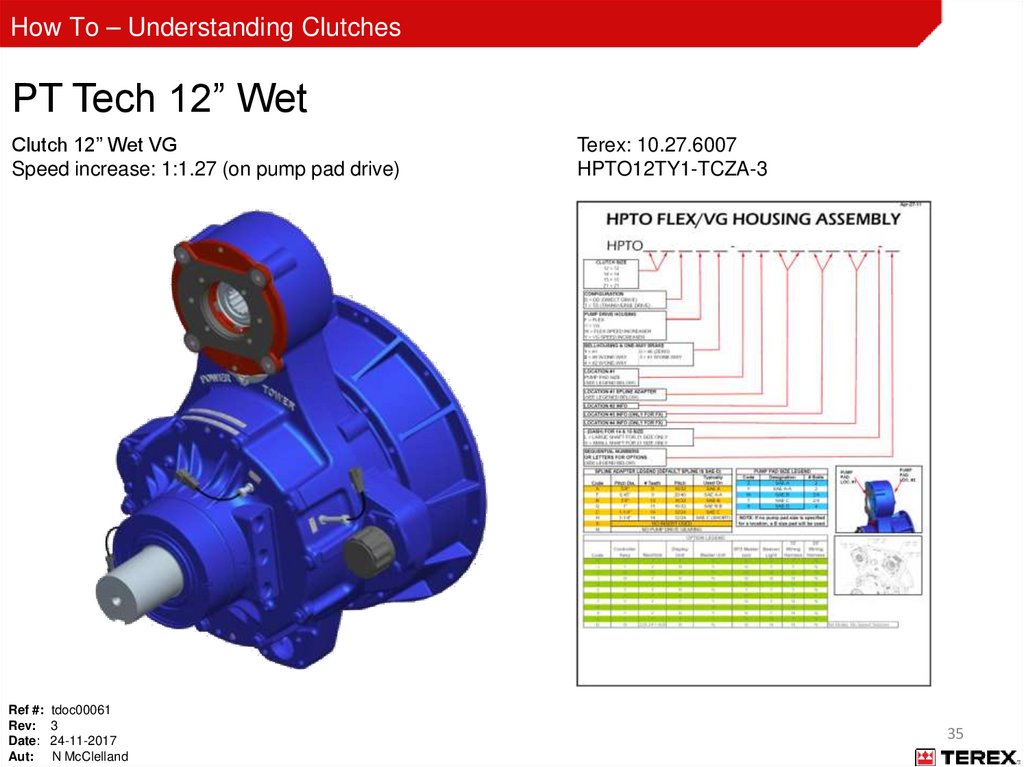
How To – Understanding ClutchesPT Tech 12” Wet
Clutch 12” Wet VG
Speed increase: 1:1.27 (on pump pad drive)
Ref #: tdoc00061
Rev: 3
Date: 24-11-2017
Aut: N McClelland
Terex: 10.27.6007
HPTO12TY1-TCZA-3
35
36.
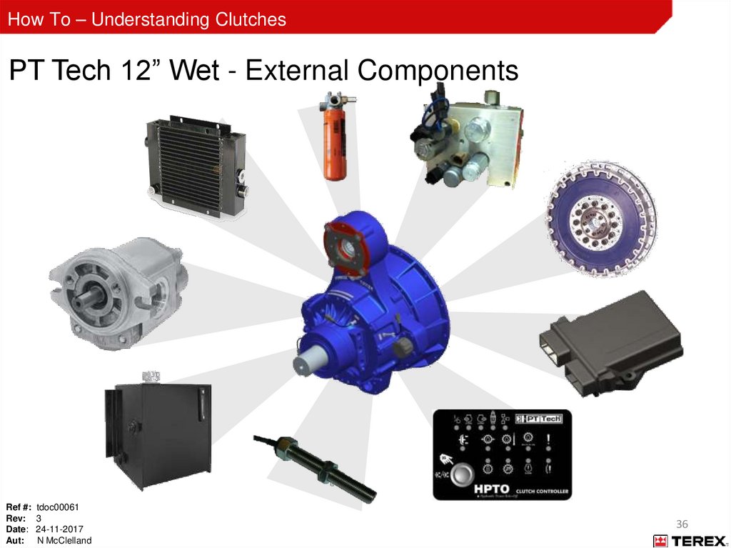
How To – Understanding ClutchesPT Tech 12” Wet - External Components
Ref #: tdoc00061
Rev: 3
Date: 24-11-2017
Aut: N McClelland
36
37.
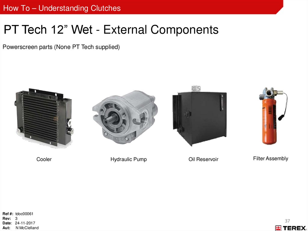
How To – Understanding ClutchesPT Tech 12” Wet - External Components
Powerscreen parts (None PT Tech supplied)
Cooler
Ref #: tdoc00061
Rev: 3
Date: 24-11-2017
Aut: N McClelland
Hydraulic Pump
Oil Reservoir
Filter Assembly
37
38.
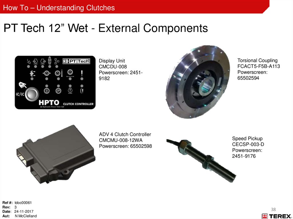
How To – Understanding ClutchesPT Tech 12” Wet - External Components
Display Unit
CMCDU-008
Powerscreen: 24519182
ADV 4 Clutch Controller
CMCMU-008-12WA
Powerscreen: 65502598
Ref #: tdoc00061
Rev: 3
Date: 24-11-2017
Aut: N McClelland
Torsional Coupling
FCACT5-F5B-A113
Powerscreen:
65502594
Speed Pickup
CECSP-003-D
Powerscreen:
2451-9176
38
39.
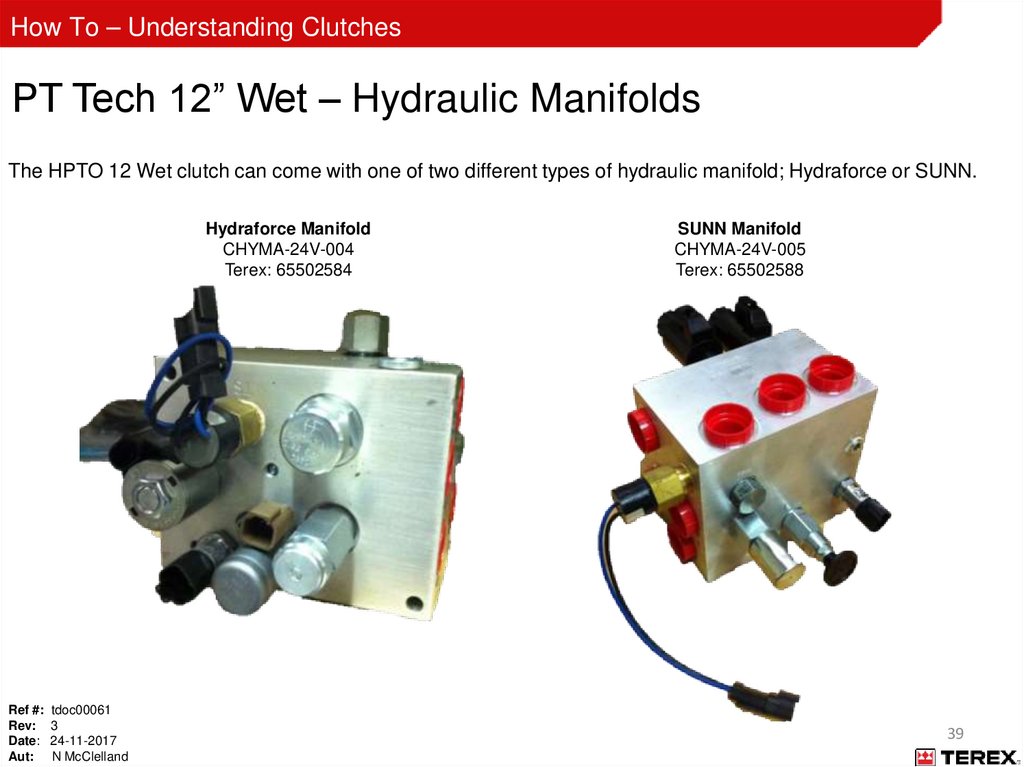
How To – Understanding ClutchesPT Tech 12” Wet – Hydraulic Manifolds
The HPTO 12 Wet clutch can come with one of two different types of hydraulic manifold; Hydraforce or SUNN.
Hydraforce Manifold
CHYMA-24V-004
Terex: 65502584
Ref #: tdoc00061
Rev: 3
Date: 24-11-2017
Aut: N McClelland
SUNN Manifold
CHYMA-24V-005
Terex: 65502588
39
40.
How To – Understanding ClutchesPT Tech 12” Wet – Hydraforce Manifold
400Psi (27.6 Bar) Relief Valve - CHYRV-400-001
Powerscreen part number: - 10.27.6004
Ref #: tdoc00061
Rev: 3
Date: 24-11-2017
Aut: N McClelland
40
41.
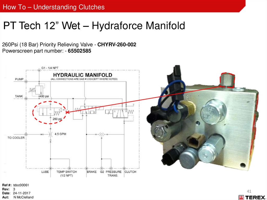
How To – Understanding ClutchesPT Tech 12” Wet – Hydraforce Manifold
260Psi (18 Bar) Priority Relieving Valve - CHYRV-260-002
Powerscreen part number: - 65502585
Ref #: tdoc00061
Rev: 3
Date: 24-11-2017
Aut: N McClelland
41
42.
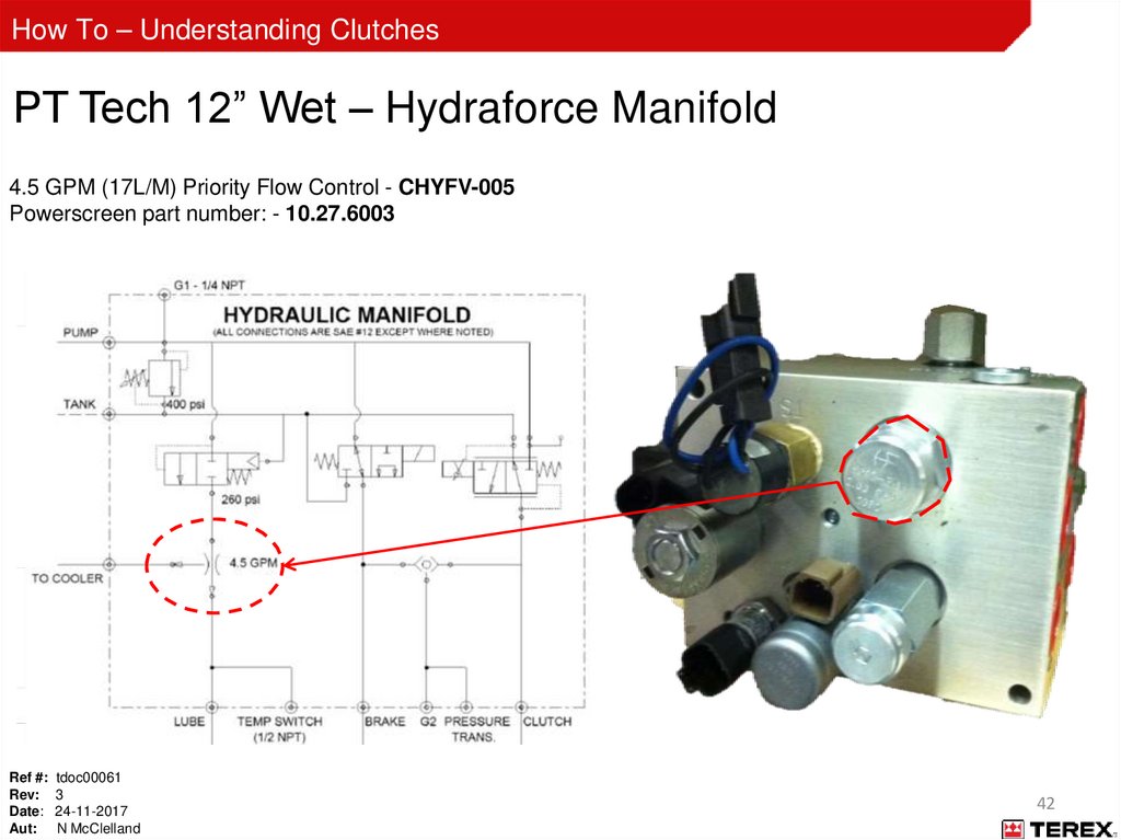
How To – Understanding ClutchesPT Tech 12” Wet – Hydraforce Manifold
4.5 GPM (17L/M) Priority Flow Control - CHYFV-005
Powerscreen part number: - 10.27.6003
Ref #: tdoc00061
Rev: 3
Date: 24-11-2017
Aut: N McClelland
42
43.
How To – Understanding ClutchesPT Tech 12” Wet – Hydraforce Manifold
200⁰F (93⁰C) Temperature Switch - CHYTS-200-001-D
Powerscreen part number: - 60541014
Ref #: tdoc00061
Rev: 3
Date: 24-11-2017
Aut: N McClelland
43
44.
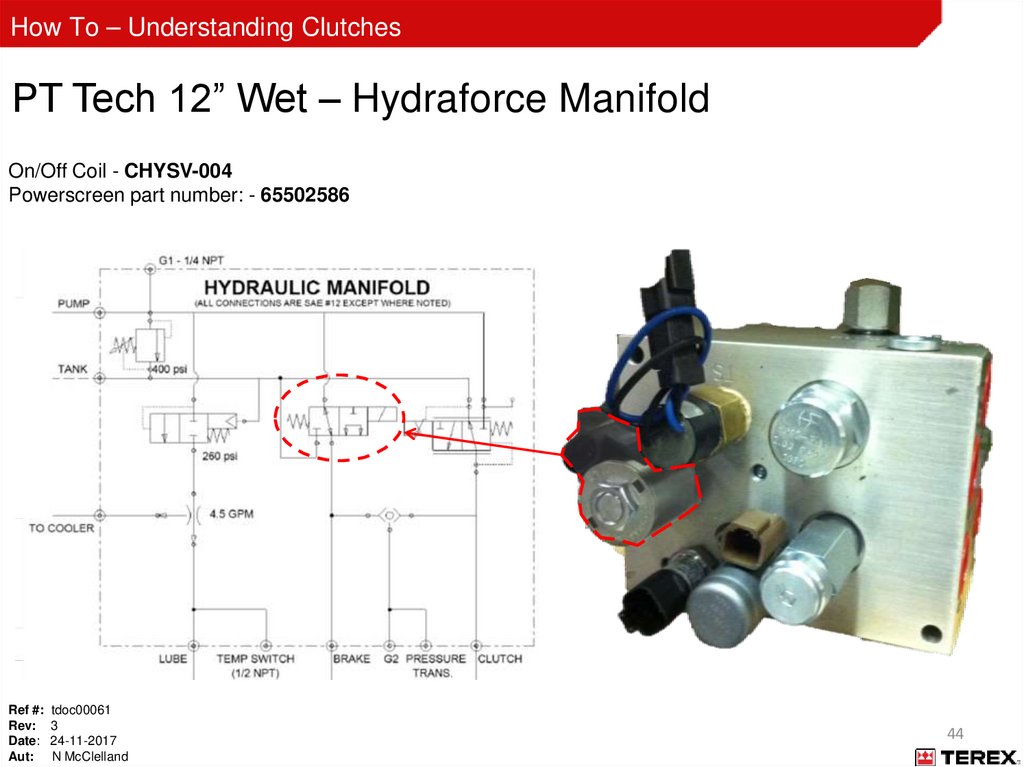
How To – Understanding ClutchesPT Tech 12” Wet – Hydraforce Manifold
On/Off Coil - CHYSV-004
Powerscreen part number: - 65502586
Ref #: tdoc00061
Rev: 3
Date: 24-11-2017
Aut: N McClelland
44
45.
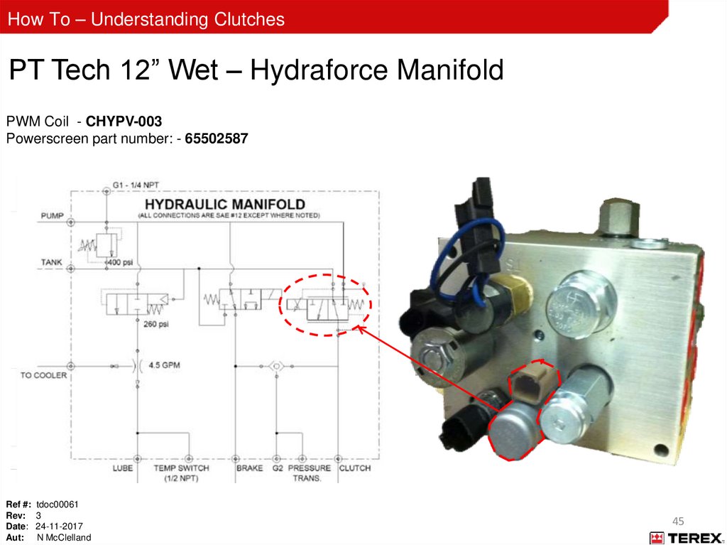
How To – Understanding ClutchesPT Tech 12” Wet – Hydraforce Manifold
PWM Coil - CHYPV-003
Powerscreen part number: - 65502587
Ref #: tdoc00061
Rev: 3
Date: 24-11-2017
Aut: N McClelland
45
46.
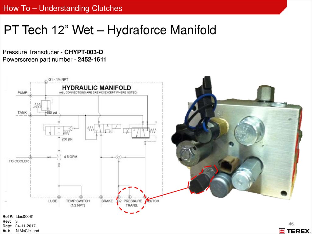
How To – Understanding ClutchesPT Tech 12” Wet – Hydraforce Manifold
Pressure Transducer - CHYPT-003-D
Powerscreen part number - 2452-1611
Ref #: tdoc00061
Rev: 3
Date: 24-11-2017
Aut: N McClelland
46
47.
How To – Understanding ClutchesOperation: Key On
24 Volts
Ref #: tdoc00061
Rev: 3
Date: 24-11-2017
Aut: N McClelland
5 AMP
+ 12 Volts
GP1 =
0 Psi
GP2 =
0 Psi
0.8 to 1.2 volt
47
48.
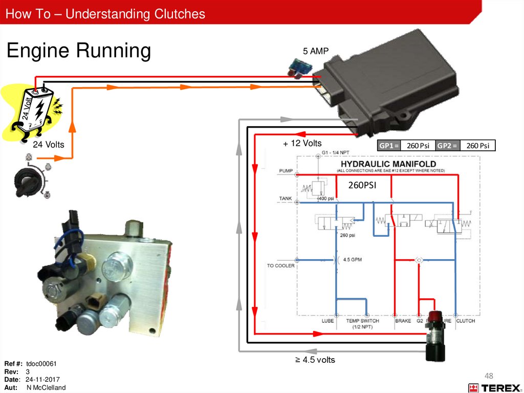
How To – Understanding ClutchesEngine Running
24 Volts
5 AMP
+ 12 Volts
GP1 = 260 Psi GP2 =
260 Psi
260PSI
Ref #: tdoc00061
Rev: 3
Date: 24-11-2017
Aut: N McClelland
≥ 4.5 volts
48
49.
How To – Understanding ClutchesEngaging
5 AMP
+ 12 Volts
24 Volts
GP1 = 260 Psi GP2 = 0-225 Psi
ON/OFF Valve
PWM Valve
Ref #: tdoc00061
Rev: 3
Date: 24-11-2017
Aut: N McClelland
4 volts
49
50.
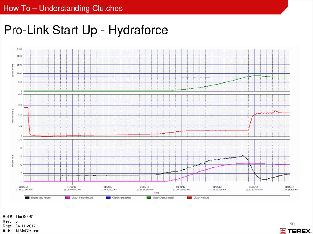
How To – Understanding ClutchesPro-Link Start Up - Hydraforce
Ref #: tdoc00061
Rev: 3
Date: 24-11-2017
Aut: N McClelland
50
51.
How To – Understanding ClutchesEngaged
5 AMP
+ 12 Volts
24 Volts
GP1 = 260 Psi GP2 =
225 Psi
ON/OFF Valve
PWM Valve
Ref #: tdoc00061
Rev: 3
Date: 24-11-2017
Aut: N McClelland
4 volts
51
52.
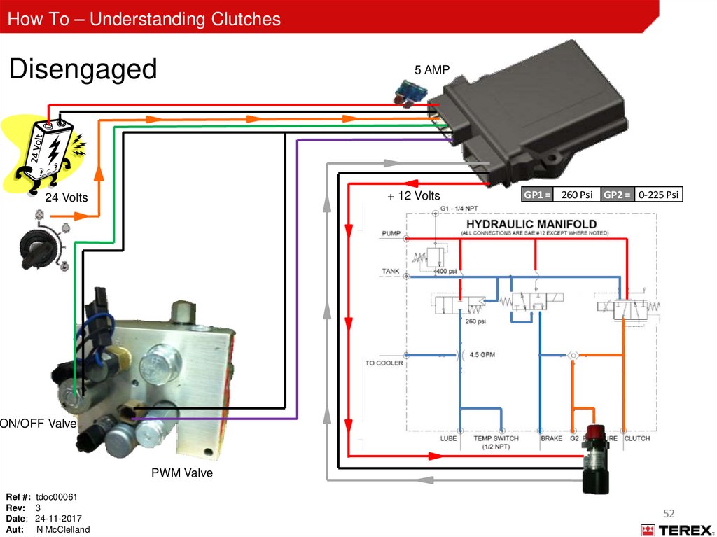
How To – Understanding ClutchesDisengaged
5 AMP
+ 12 Volts
24 Volts
GP1 = 260 Psi GP2 = 0-225 Psi
ON/OFF Valve
PWM Valve
Ref #: tdoc00061
Rev: 3
Date: 24-11-2017
Aut: N McClelland
52
53.
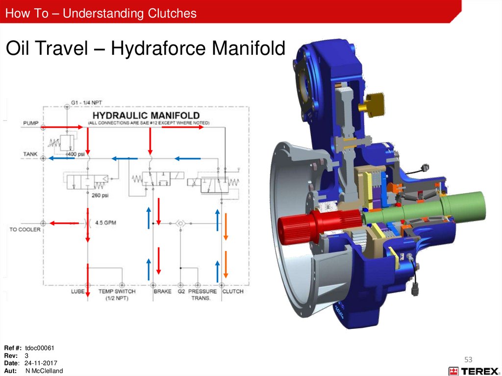
How To – Understanding ClutchesOil Travel – Hydraforce Manifold
Ref #: tdoc00061
Rev: 3
Date: 24-11-2017
Aut: N McClelland
53
54.
How To – Understanding ClutchesPT Tech 12” Wet – SUNN Manifold
500 Psi Relief Valve - CHYRV-500-001
Ref #: tdoc00061
Rev: 3
Date: 24-11-2017
Aut: N McClelland
Powerscreen Part No: - 65502589
54
55.
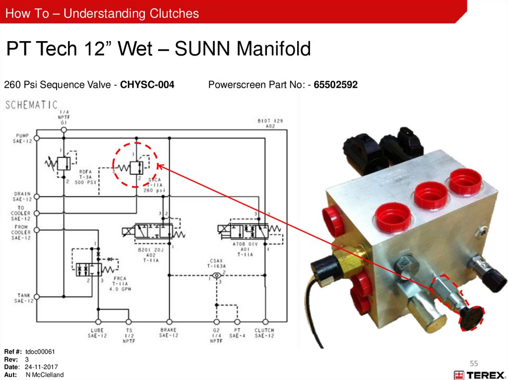
How To – Understanding ClutchesPT Tech 12” Wet – SUNN Manifold
260 Psi Sequence Valve - CHYSC-004
Ref #: tdoc00061
Rev: 3
Date: 24-11-2017
Aut: N McClelland
Powerscreen Part No: - 65502592
55
56.
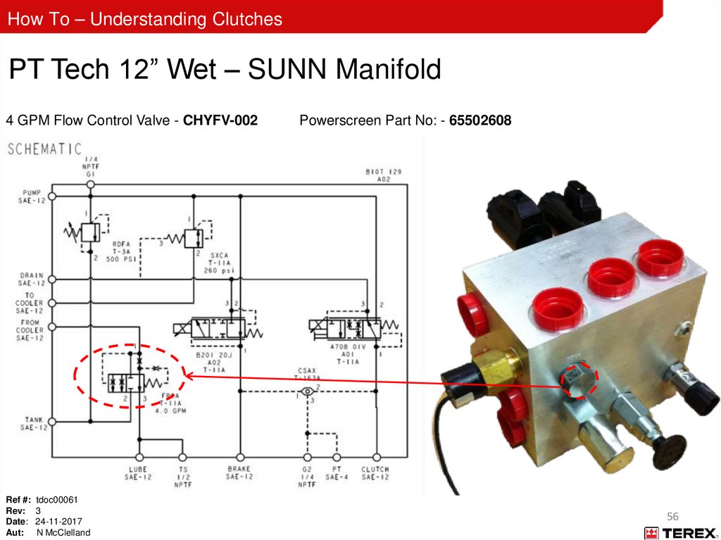
How To – Understanding ClutchesPT Tech 12” Wet – SUNN Manifold
4 GPM Flow Control Valve - CHYFV-002
Ref #: tdoc00061
Rev: 3
Date: 24-11-2017
Aut: N McClelland
Powerscreen Part No: - 65502608
56
57.
How To – Understanding ClutchesPT Tech 12” Wet – SUNN Manifold
Temperature Switch - CHYTS-200-001-D
Ref #: tdoc00061
Rev: 3
Date: 24-11-2017
Aut: N McClelland
Powerscreen Part No: - 60541014
57
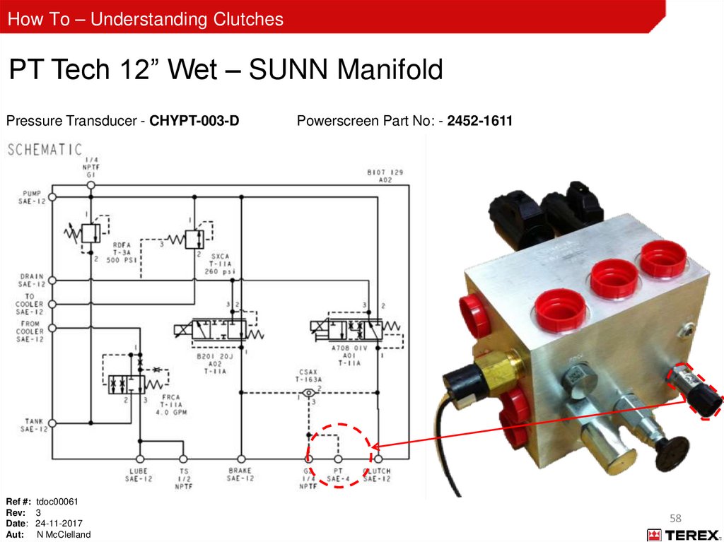
58.
How To – Understanding ClutchesPT Tech 12” Wet – SUNN Manifold
Pressure Transducer - CHYPT-003-D
Ref #: tdoc00061
Rev: 3
Date: 24-11-2017
Aut: N McClelland
Powerscreen Part No: - 2452-1611
58
59.
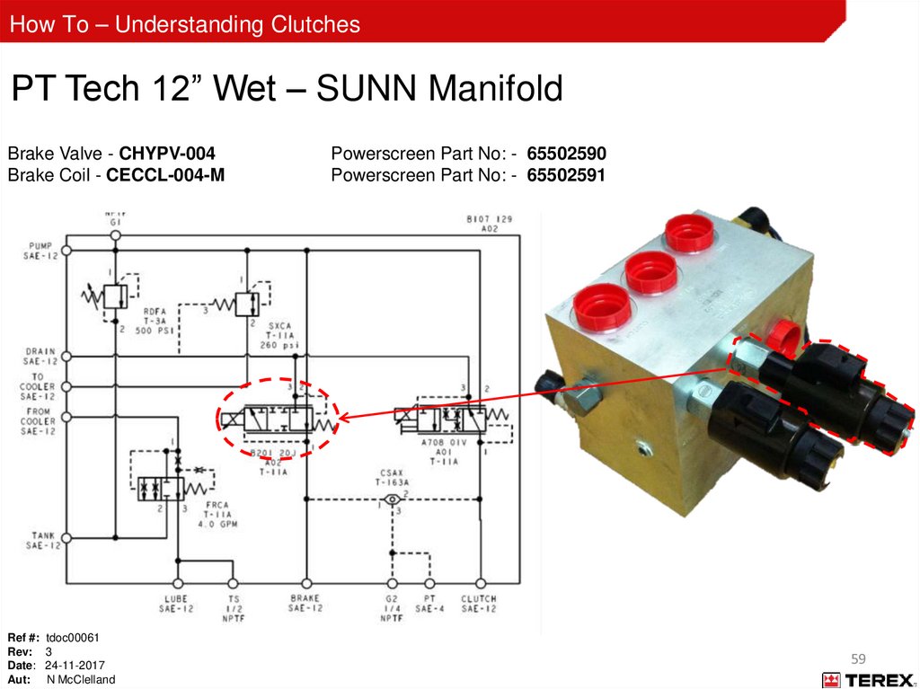
How To – Understanding ClutchesPT Tech 12” Wet – SUNN Manifold
Brake Valve - CHYPV-004
Brake Coil - CECCL-004-M
Ref #: tdoc00061
Rev: 3
Date: 24-11-2017
Aut: N McClelland
Powerscreen Part No: - 65502590
Powerscreen Part No: - 65502591
59
60.
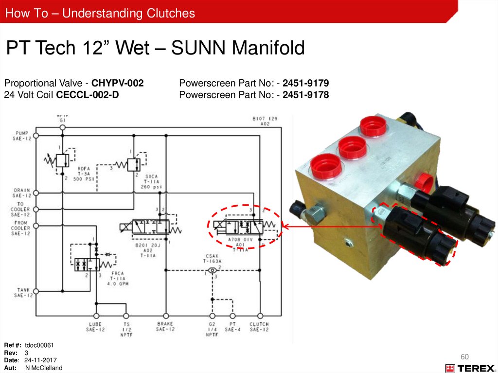
How To – Understanding ClutchesPT Tech 12” Wet – SUNN Manifold
Proportional Valve - CHYPV-002
24 Volt Coil CECCL-002-D
Ref #: tdoc00061
Rev: 3
Date: 24-11-2017
Aut: N McClelland
Powerscreen Part No: - 2451-9179
Powerscreen Part No: - 2451-9178
60
61.
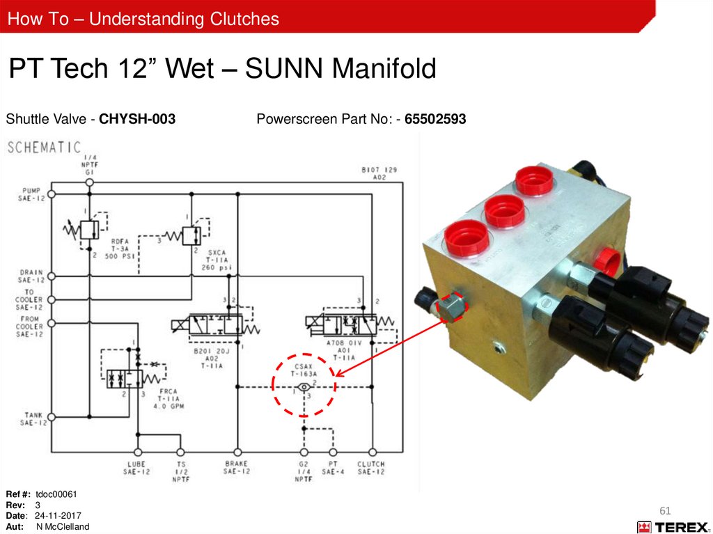
How To – Understanding ClutchesPT Tech 12” Wet – SUNN Manifold
Shuttle Valve - CHYSH-003
Ref #: tdoc00061
Rev: 3
Date: 24-11-2017
Aut: N McClelland
Powerscreen Part No: - 65502593
61
62.
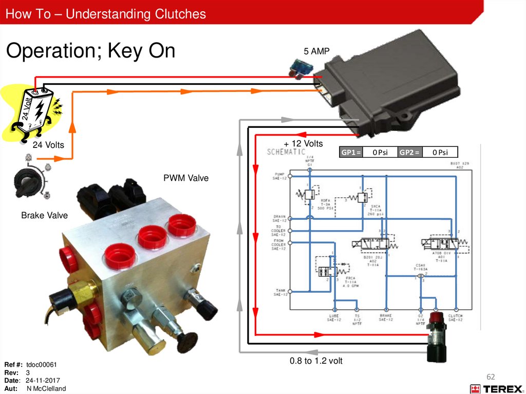
How To – Understanding ClutchesOperation; Key On
5 AMP
+ 12 Volts
24 Volts
GP1 =
0 Psi
GP2 =
0 Psi
PWM Valve
Brake Valve
Ref #: tdoc00061
Rev: 3
Date: 24-11-2017
Aut: N McClelland
0.8 to 1.2 volt
62
63.
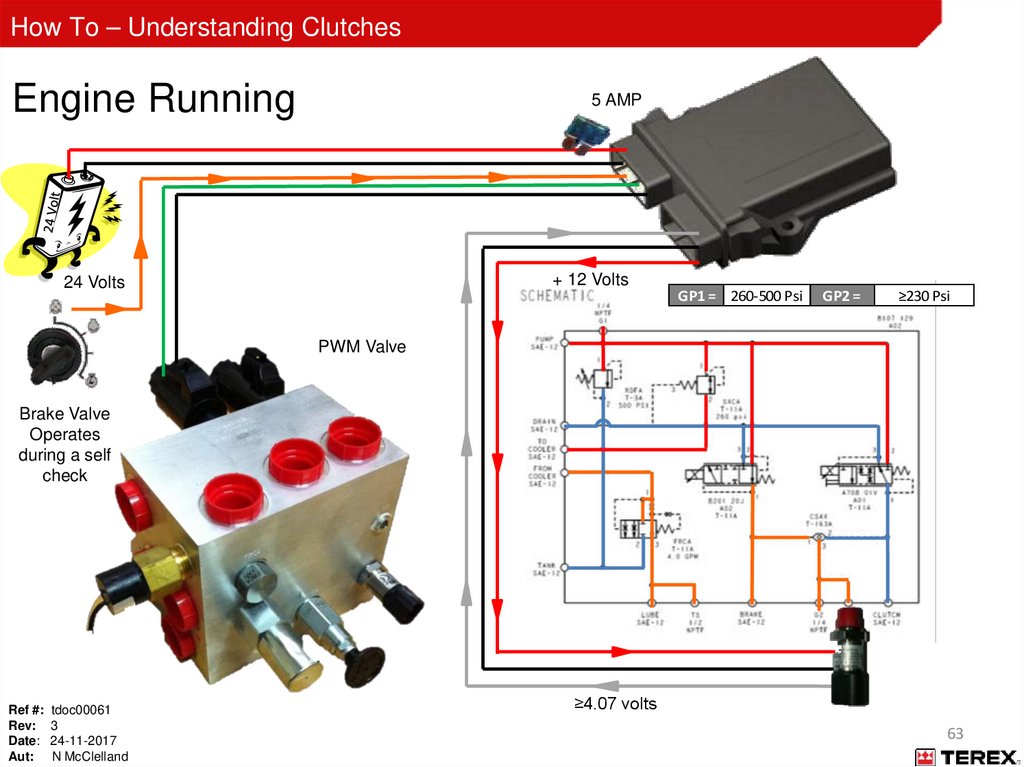
How To – Understanding ClutchesEngine Running
5 AMP
+ 12 Volts
24 Volts
GP1 = 260-500 Psi
GP2 =
≥230 Psi
PWM Valve
Brake Valve
Operates
during a self
check
Ref #: tdoc00061
Rev: 3
Date: 24-11-2017
Aut: N McClelland
≥4.07 volts
63
64.
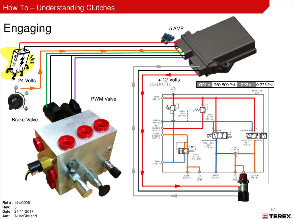
How To – Understanding ClutchesEngaging
5 AMP
+ 12 Volts
24 Volts
GP1 = 260-500 Psi
GP2 =
0-225 Psi
PWM Valve
Brake Valve
Ref #: tdoc00061
Rev: 3
Date: 24-11-2017
Aut: N McClelland
64
65.
How To – Understanding ClutchesPro-Link Start Up - SUNN
Ref #: tdoc00061
Rev: 3
Date: 24-11-2017
Aut: N McClelland
65
66.
How To – Understanding ClutchesEngaged
5 AMP
+ 12 Volts
24 Volts
GP1 = 260-500 Psi
GP2 =
225 Psi
PWM Valve
Brake Valve
Ref #: tdoc00061
Rev: 3
Date: 24-11-2017
Aut: N McClelland
4 volts
66
67.
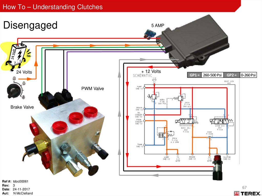
How To – Understanding ClutchesDisengaged
5 AMP
+ 12 Volts
24 Volts
GP1 = 260-500 Psi
GP2 =
0-260 Psi
PWM Valve
Brake Valve
Ref #: tdoc00061
Rev: 3
Date: 24-11-2017
Aut: N McClelland
67
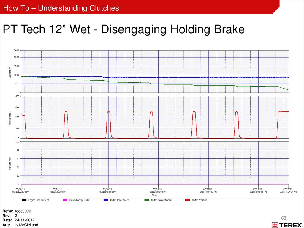
68.
How To – Understanding ClutchesPT Tech 12” Wet - Disengaging Holding Brake
Ref #: tdoc00061
Rev: 3
Date: 24-11-2017
Aut: N McClelland
68
69.
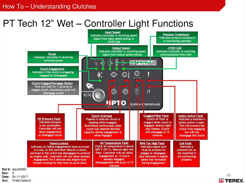
How To – Understanding ClutchesPT Tech 12” Wet – Controller Light Functions
Ref #: tdoc00061
Rev: 3
Date: 24-11-2017
Aut: N McClelland
69
70.
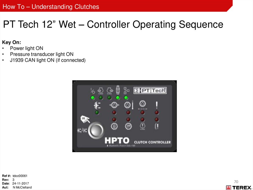
How To – Understanding ClutchesPT Tech 12” Wet – Controller Operating Sequence
Key On:
• Power light ON
• Pressure transducer light ON
• J1939 CAN light ON (if connected)
Ref #: tdoc00061
Rev: 3
Date: 24-11-2017
Aut: N McClelland
70
71.
How To – Understanding ClutchesPT Tech 12” Wet - Controller Operating Sequence
Engine Running, Clutch Disengaged:
• Power light ON
• Pressure transducer light ON
• J1939 CAN light ON (if connected)
• Input speed light ON
• Pressure in ‘GP2’ port of manifold is at least 260 psi (17.9 bar) (+/- 10%)
Ref #: tdoc00061
Rev: 3
Date: 24-11-2017
Aut: N McClelland
71
72.
How To – Understanding ClutchesPT Tech 12” Wet - Controller Operating Sequence
Engine Running, Clutch Engaging:
• Power light ON
• Pressure transducer light ON
• J1939 CAN light ON (if connected)
• Input speed light ON
• Output speed light ON when shaft rotation begins
• Pressure in “GP2” port of manifold drops to 0 psi
when engage button is pressed
Ref #: tdoc00061
Rev: 3
Date: 24-11-2017
Aut: N McClelland
Clutch engaged light flashes after button is held for 3
seconds
Controller “ramps” clutch pressure until output and
input speed are equal
Pressure in “GP2” port increases during clutch
engagement process
72
73.
How To – Understanding ClutchesPT Tech 12” Wet - Controller Operating Sequence
Engine Running, Clutch Engaged:
• Power light ON
• Pressure transducer light ON
• J1939 CAN light ON (if connected)
• Input speed light ON
• Output Speed light ON
• Clutch engaged light ON
• Pressure in “GP2” port of manifold is 225 psi (15.5 bar)
Ref #: tdoc00061
Rev: 3
Date: 24-11-2017
Aut: N McClelland
73
74.
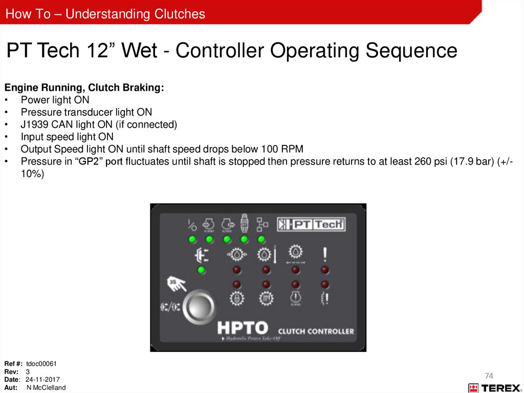
How To – Understanding ClutchesPT Tech 12” Wet - Controller Operating Sequence
Engine Running, Clutch Braking:
• Power light ON
• Pressure transducer light ON
• J1939 CAN light ON (if connected)
• Input speed light ON
• Output Speed light ON until shaft speed drops below 100 RPM
• Pressure in “GP2” port fluctuates until shaft is stopped then pressure returns to at least 260 psi (17.9 bar) (+/10%)
Ref #: tdoc00061
Rev: 3
Date: 24-11-2017
Aut: N McClelland
74
75.
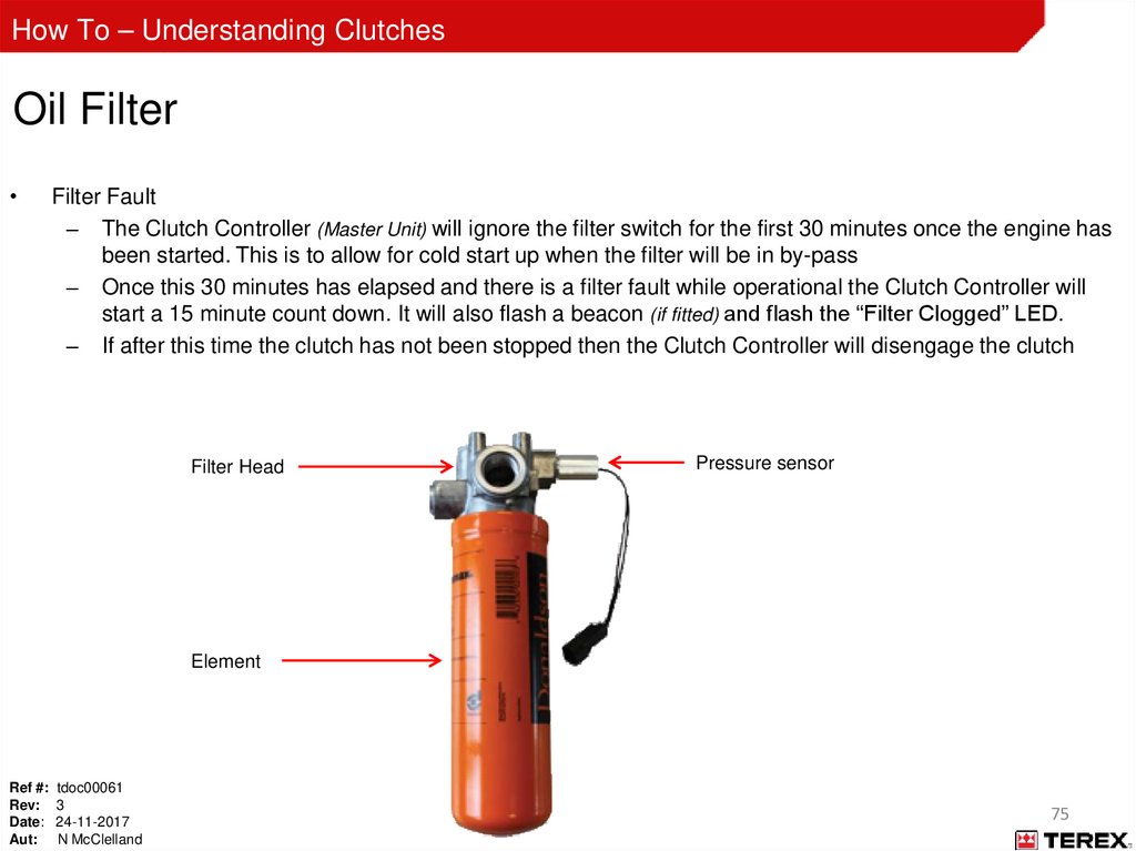
How To – Understanding ClutchesOil Filter
Filter Fault
– The Clutch Controller (Master Unit) will ignore the filter switch for the first 30 minutes once the engine has
been started. This is to allow for cold start up when the filter will be in by-pass
– Once this 30 minutes has elapsed and there is a filter fault while operational the Clutch Controller will
start a 15 minute count down. It will also flash a beacon (if fitted) and flash the “Filter Clogged” LED.
– If after this time the clutch has not been stopped then the Clutch Controller will disengage the clutch
Filter Head
Pressure sensor
Element
Ref #: tdoc00061
Rev: 3
Date: 24-11-2017
Aut: N McClelland
75
76.
How To – Understanding ClutchesADV 4 Clutch Controller (CMCMU-008-12WA)
Beginning May 2012, controller types are distinguished by label colour. Ensure the correct master unit is being
used by using the below table.
See “Appendix C” for machine details on controller types
Ref #: tdoc00061
Rev: 3
Date: 24-11-2017
Aut: N McClelland
76
77.
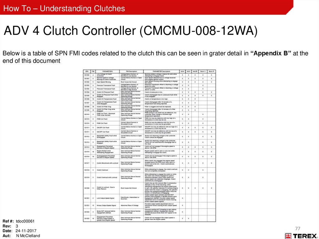
How To – Understanding ClutchesADV 4 Clutch Controller (CMCMU-008-12WA)
Below is a table of SPN FMI codes related to the clutch this can be seen in grater detail in “Appendix B” at the
end of this document
Ref #: tdoc00061
Rev: 3
Date: 24-11-2017
Aut: N McClelland
77
78.
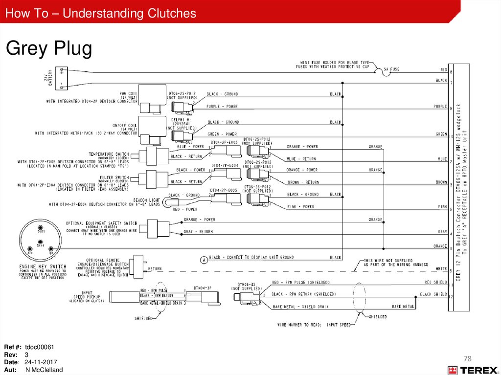
How To – Understanding ClutchesGrey Plug
Ref #: tdoc00061
Rev: 3
Date: 24-11-2017
Aut: N McClelland
78
79.
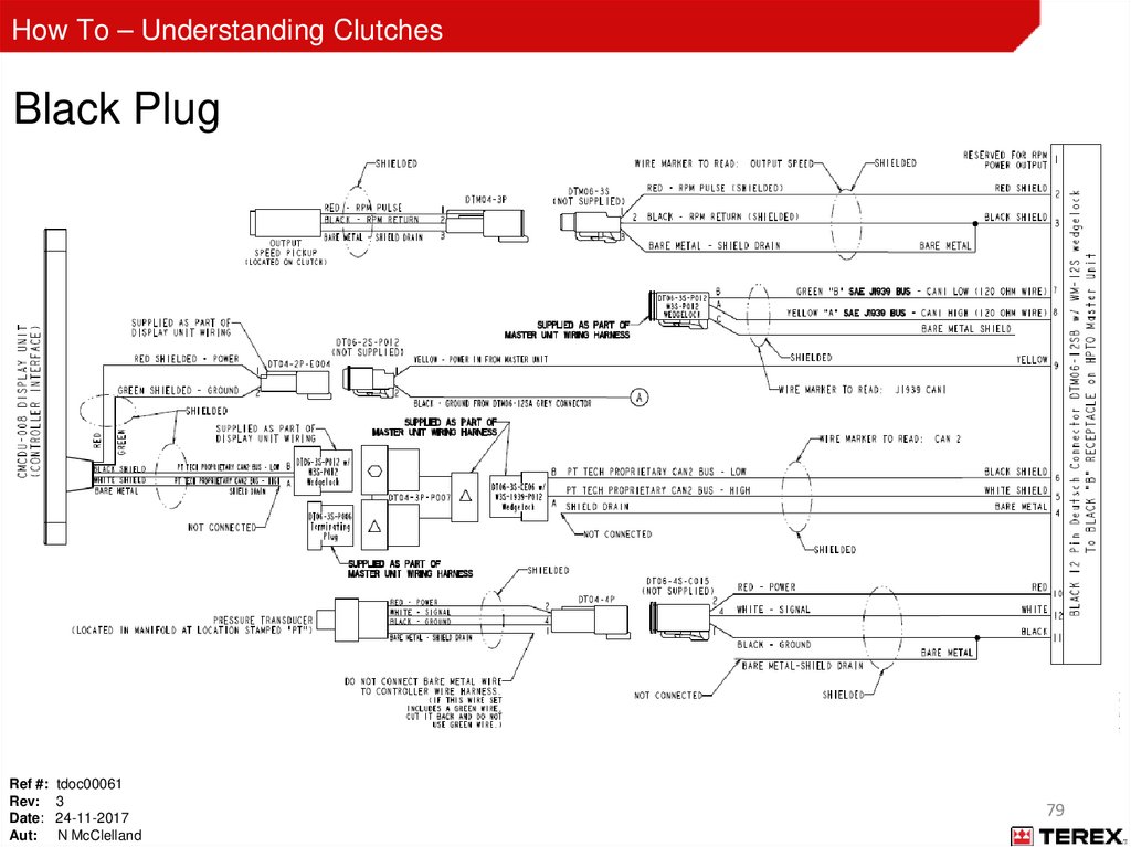
How To – Understanding ClutchesBlack Plug
Ref #: tdoc00061
Rev: 3
Date: 24-11-2017
Aut: N McClelland
79
80.
How To – Understanding ClutchesPT Tech 12” Wet - Maintenance
Initial 10 hours
–
–
–
–
–
Check clutch supply oil level
Check hydraulic connections
Check bolt tension
All electrical connections
Obtain oil base line
Daily
–
–
–
Check the oil level
Check breather for clogs or obstructions
Check ventilation holes in bell housing for clogs and obstructions
Every 500 hours
Every 1000 hours
–
–
–
–
–
–
Replace oil filter (don’t overfill)
Replace oil filter
Replace tank breather
Replace clutch breather
Oil sample (compare against base line for any treads)
Inspect pump drive gears
5000 hours
–
Internal inspection and service
• Contact PT Tech Representative
Ref #: tdoc00061
Rev: 3
Date: 24-11-2017
Aut: N McClelland
80
81.
How To – Understanding ClutchesPT Tech 12” Wet – Oil Information
Below -4⁰F (-20⁰C)
-4⁰F to 32⁰F (-20⁰C to 0⁰C)
Above 32⁰F (0⁰C)
Caterpillar Arctic (Cold
weather TDTO)
Mobilfluid LT
Mobilfluid 424
Shell Spirax S3 TLV
Caterpillar TDTO (10W only)
ESSO Hydraul50
Shell Spirax S4 TXM
Oi
l
Ty
pe
s
Temperature Range
ESSO Hydraul 56
Vermeer VMF Ultra Gold
Ref #: tdoc00061
Rev: 3
Date: 24-11-2017
Aut: N McClelland
81
82.
How To – Understanding ClutchesPT Tech 12” Wet – Oil Information
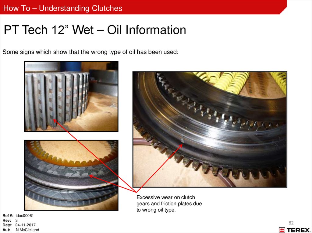
Some signs which show that the wrong type of oil has been used:
Excessive wear on clutch
gears and friction plates due
to wrong oil type.
Ref #: tdoc00061
Rev: 3
Date: 24-11-2017
Aut: N McClelland
82
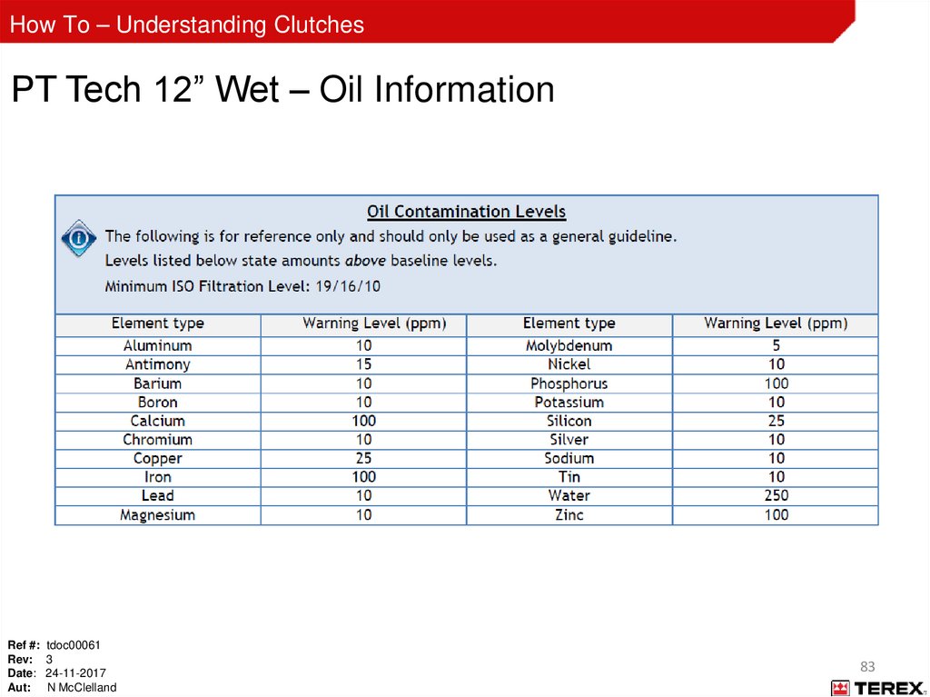
83.
How To – Understanding ClutchesPT Tech 12” Wet – Oil Information
Ref #: tdoc00061
Rev: 3
Date: 24-11-2017
Aut: N McClelland
83
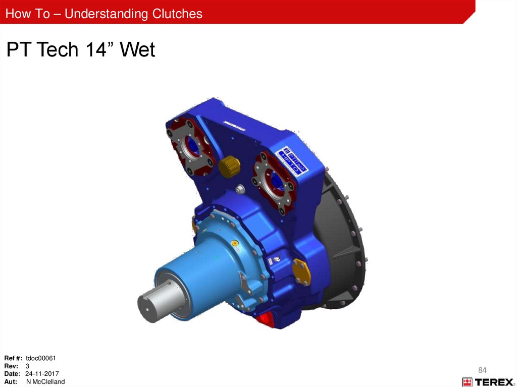
84.
How To – Understanding ClutchesPT Tech 14” Wet
Ref #: tdoc00061
Rev: 3
Date: 24-11-2017
Aut: N McClelland
84
85.
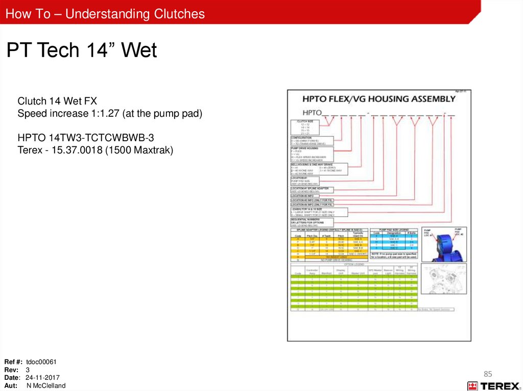
How To – Understanding ClutchesPT Tech 14” Wet
Clutch 14 Wet FX
Speed increase 1:1.27 (at the pump pad)
HPTO 14TW3-TCTCWBWB-3
Terex - 15.37.0018 (1500 Maxtrak)
Ref #: tdoc00061
Rev: 3
Date: 24-11-2017
Aut: N McClelland
85
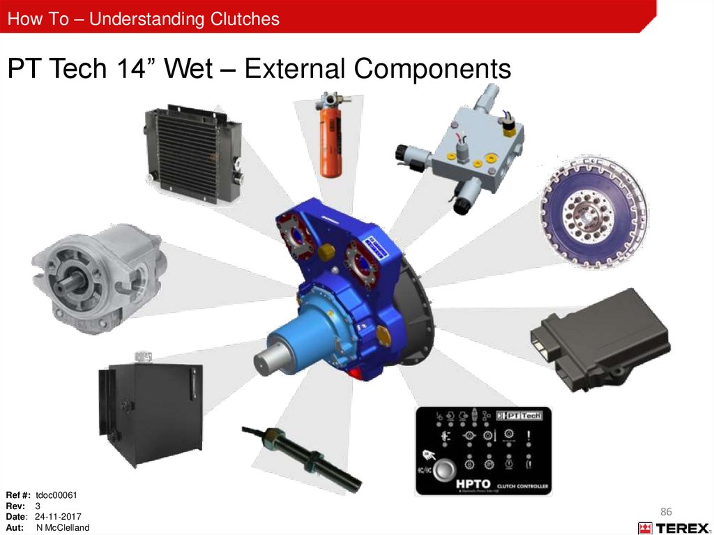
86.
How To – Understanding ClutchesPT Tech 14” Wet – External Components
Ref #: tdoc00061
Rev: 3
Date: 24-11-2017
Aut: N McClelland
86
87.
How To – Understanding ClutchesPT Tech 14” Wet - External Components
Powerscreen parts (None PT Tech supplied)
Cooler
Ref #: tdoc00061
Rev: 3
Date: 24-11-2017
Aut: N McClelland
Hydraulic Pump
Oil Reservoir
Filter Assembly
87
88.
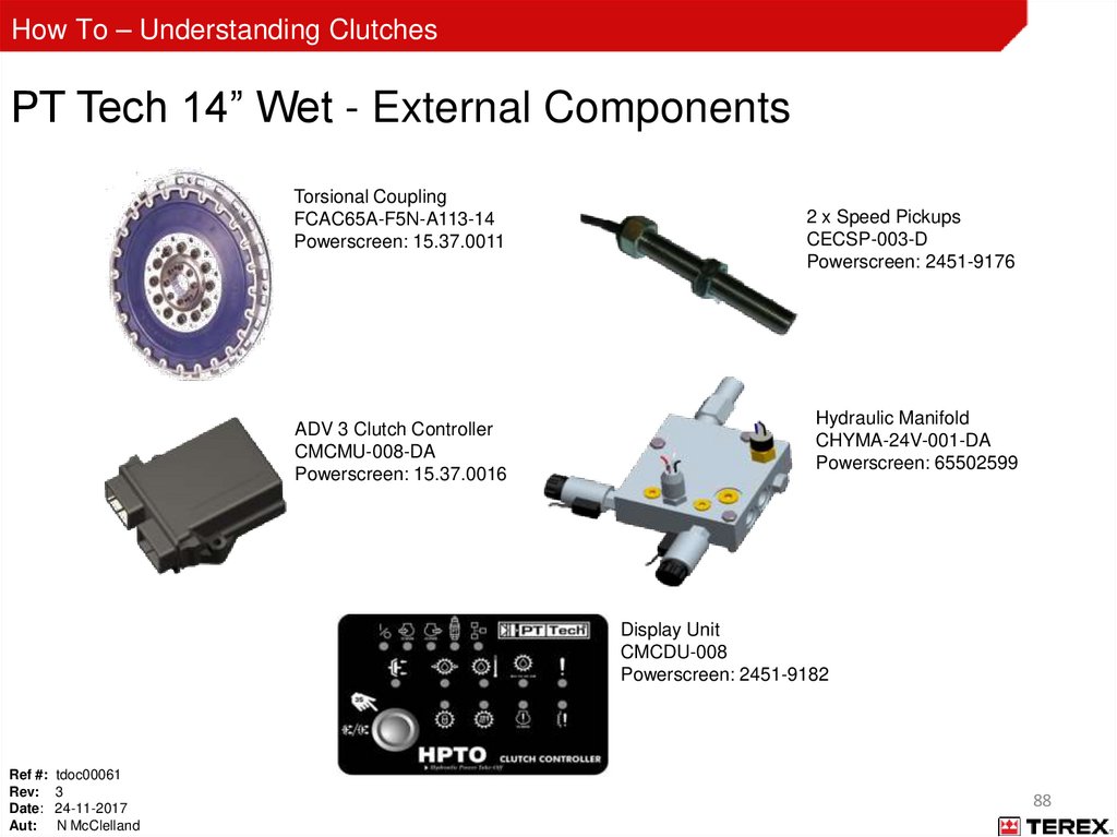
How To – Understanding ClutchesPT Tech 14” Wet - External Components
Torsional Coupling
FCAC65A-F5N-A113-14
Powerscreen: 15.37.0011
ADV 3 Clutch Controller
CMCMU-008-DA
Powerscreen: 15.37.0016
2 x Speed Pickups
CECSP-003-D
Powerscreen: 2451-9176
Hydraulic Manifold
CHYMA-24V-001-DA
Powerscreen: 65502599
Display Unit
CMCDU-008
Powerscreen: 2451-9182
Ref #: tdoc00061
Rev: 3
Date: 24-11-2017
Aut: N McClelland
88
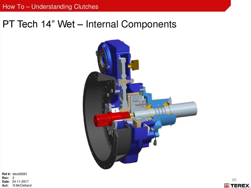
89.
How To – Understanding ClutchesPT Tech 14” Wet – Internal Components
Ref #: tdoc00061
Rev: 3
Date: 24-11-2017
Aut: N McClelland
89
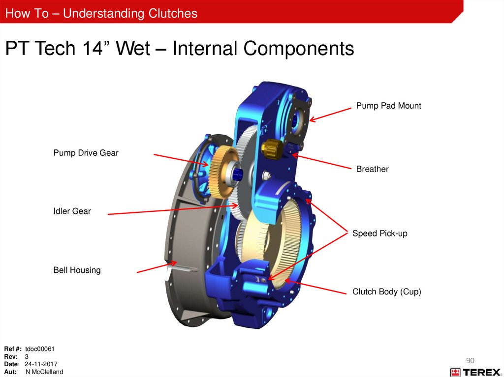
90.
How To – Understanding ClutchesPT Tech 14” Wet – Internal Components
Pump Pad Mount
Pump Drive Gear
Breather
Idler Gear
Speed Pick-up
Bell Housing
Clutch Body (Cup)
Ref #: tdoc00061
Rev: 3
Date: 24-11-2017
Aut: N McClelland
90
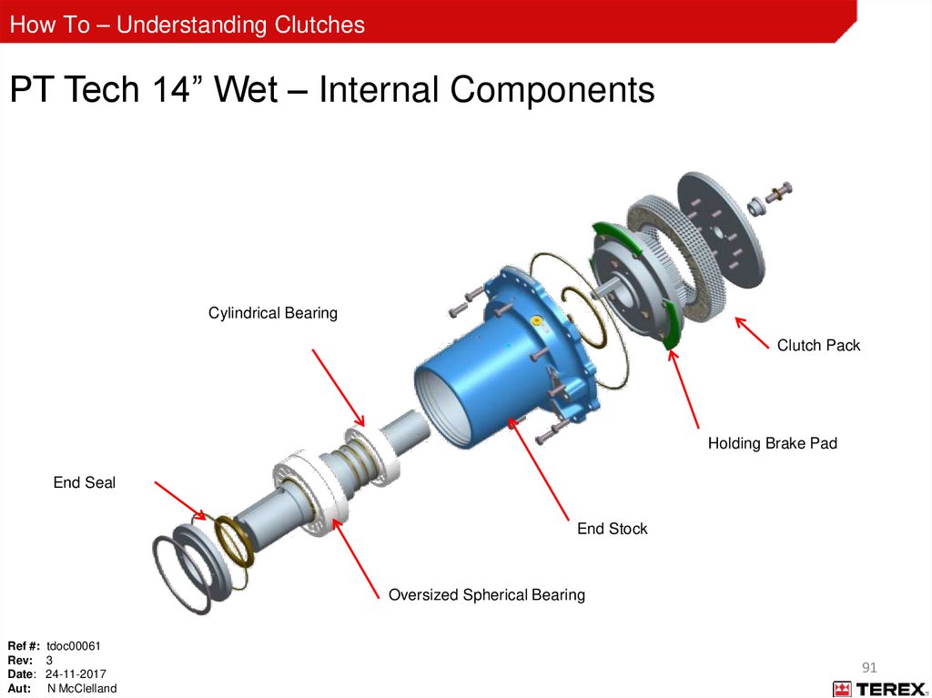
91.
How To – Understanding ClutchesPT Tech 14” Wet – Internal Components
Cylindrical Bearing
Clutch Pack
Holding Brake Pad
End Seal
End Stock
Oversized Spherical Bearing
Ref #: tdoc00061
Rev: 3
Date: 24-11-2017
Aut: N McClelland
91
92.
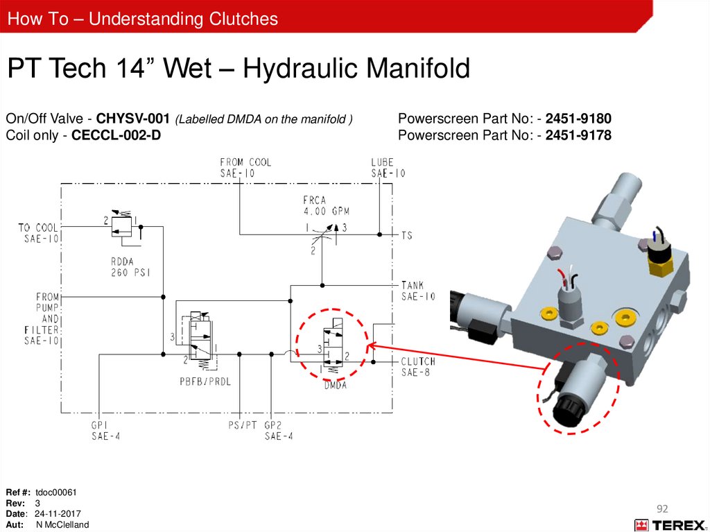
How To – Understanding ClutchesPT Tech 14” Wet – Hydraulic Manifold
On/Off Valve - CHYSV-001 (Labelled DMDA on the manifold )
Coil only - CECCL-002-D
Ref #: tdoc00061
Rev: 3
Date: 24-11-2017
Aut: N McClelland
Powerscreen Part No: - 2451-9180
Powerscreen Part No: - 2451-9178
92
93.
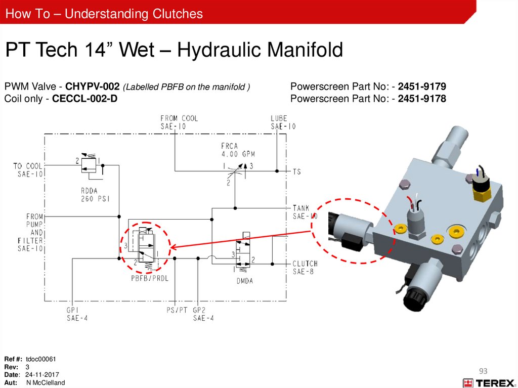
How To – Understanding ClutchesPT Tech 14” Wet – Hydraulic Manifold
PWM Valve - CHYPV-002 (Labelled PBFB on the manifold )
Coil only - CECCL-002-D
Ref #: tdoc00061
Rev: 3
Date: 24-11-2017
Aut: N McClelland
Powerscreen Part No: - 2451-9179
Powerscreen Part No: - 2451-9178
93
94.
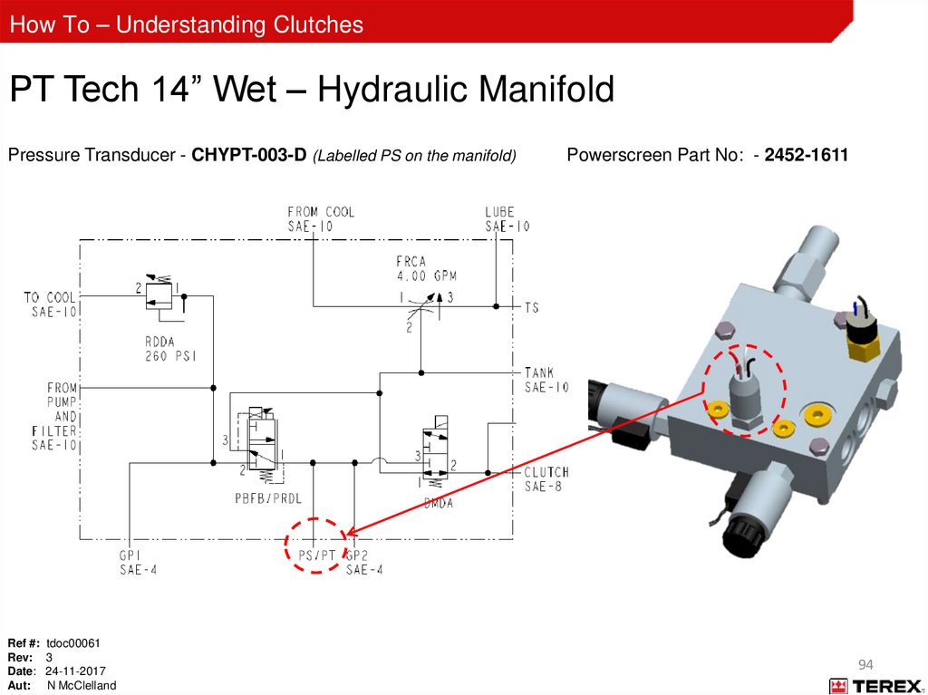
How To – Understanding ClutchesPT Tech 14” Wet – Hydraulic Manifold
Pressure Transducer - CHYPT-003-D (Labelled PS on the manifold)
Ref #: tdoc00061
Rev: 3
Date: 24-11-2017
Aut: N McClelland
Powerscreen Part No: - 2452-1611
94
95.
How To – Understanding ClutchesPT Tech 14” Wet – Hydraulic Manifold
Temperature Switch (200°F)
Ref #: tdoc00061
Rev: 3
Date: 24-11-2017
Aut: N McClelland
Powerscreen Part No: - 60541014
95
96.
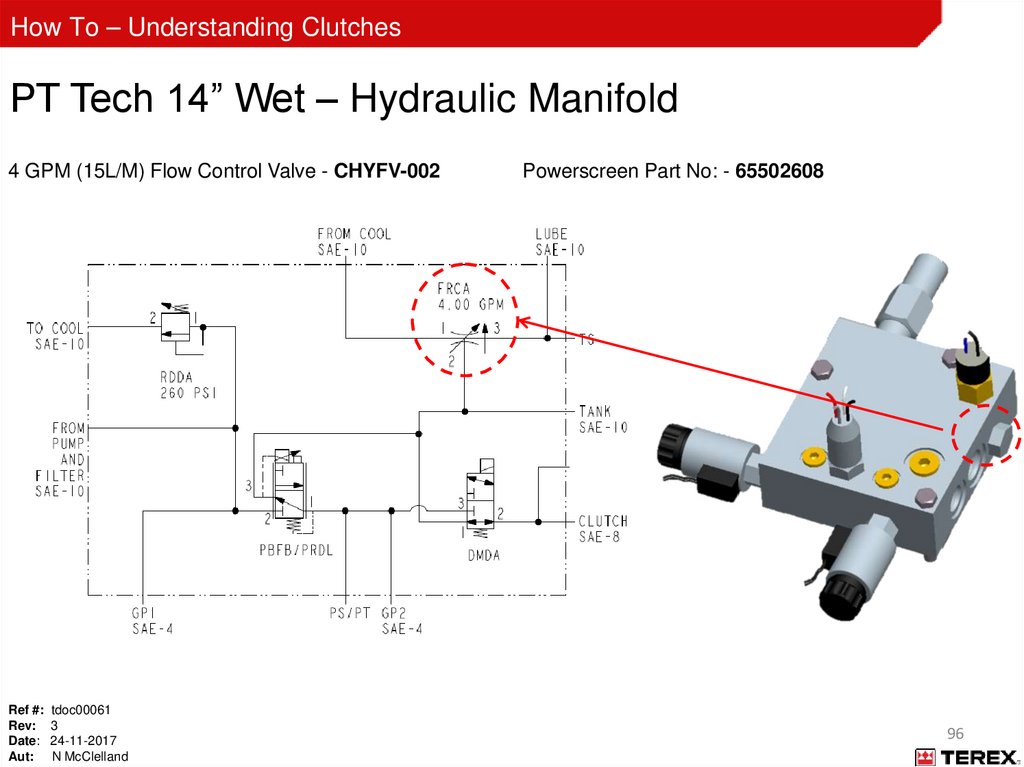
How To – Understanding ClutchesPT Tech 14” Wet – Hydraulic Manifold
4 GPM (15L/M) Flow Control Valve - CHYFV-002
Ref #: tdoc00061
Rev: 3
Date: 24-11-2017
Aut: N McClelland
Powerscreen Part No: - 65502608
96
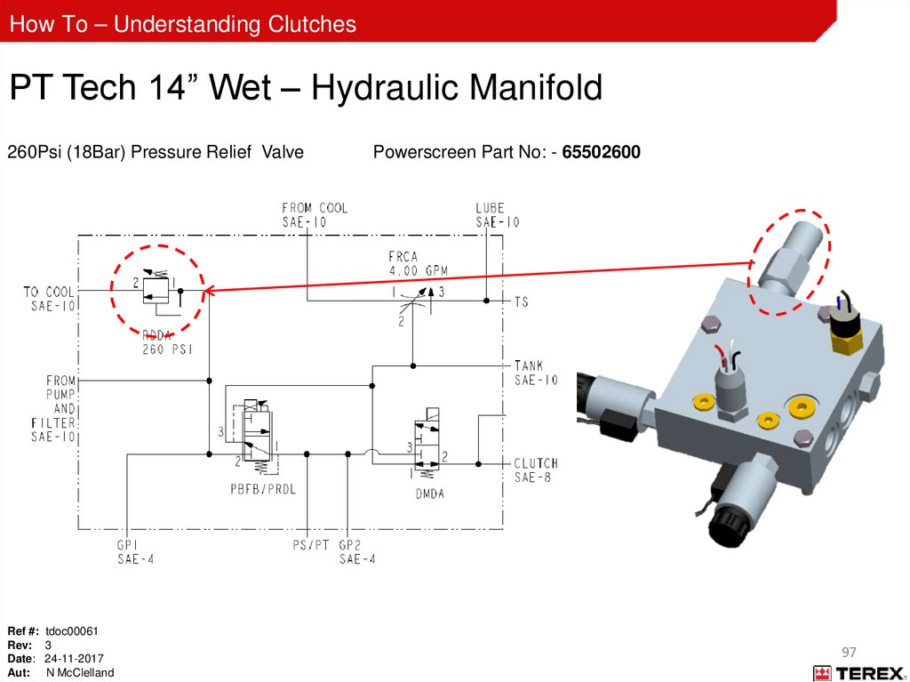
97.
How To – Understanding ClutchesPT Tech 14” Wet – Hydraulic Manifold
260Psi (18Bar) Pressure Relief Valve
Ref #: tdoc00061
Rev: 3
Date: 24-11-2017
Aut: N McClelland
Powerscreen Part No: - 65502600
97
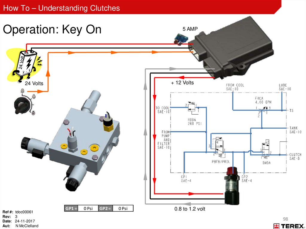
98.
How To – Understanding ClutchesOperation: Key On
5 AMP
+ 12 Volts
24 Volts
Ref #: tdoc00061
Rev: 3
Date: 24-11-2017
Aut: N McClelland
GP1 =
0 Psi
GP2 =
0 Psi
0.8 to 1.2 volt
98
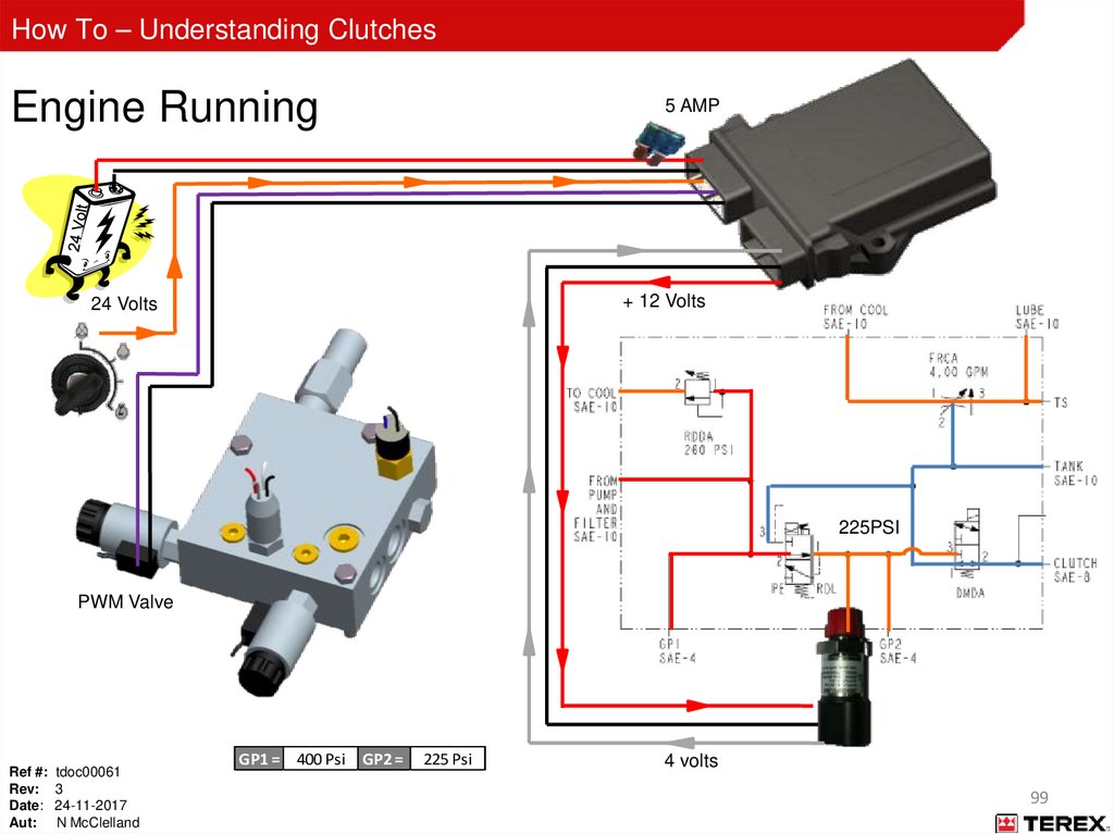
99.
How To – Understanding ClutchesEngine Running
5 AMP
+ 12 Volts
24 Volts
225PSI
PWM Valve
Ref #: tdoc00061
Rev: 3
Date: 24-11-2017
Aut: N McClelland
GP1 = 400 Psi GP2 =
225 Psi
4 volts
99
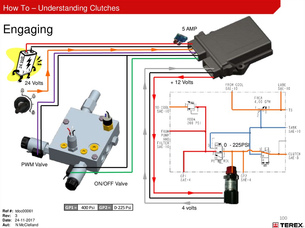
100.
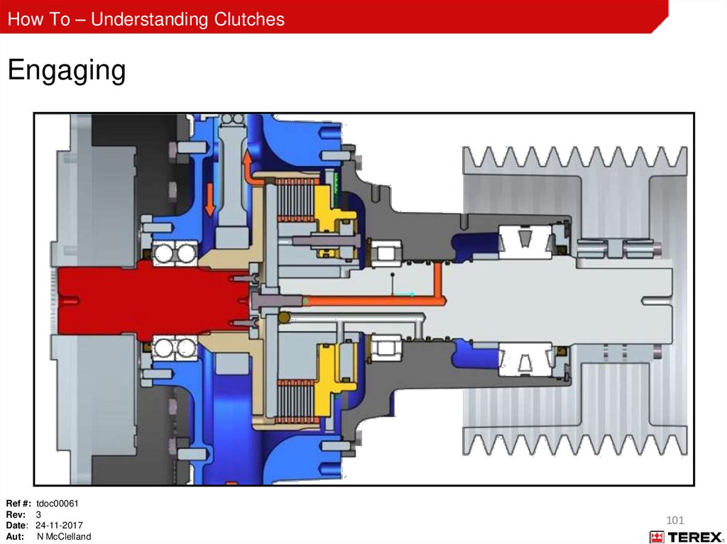
How To – Understanding ClutchesEngaging
5 AMP
+ 12 Volts
24 Volts
0 - 225PSI
PWM Valve
ON/OFF Valve
Ref #: tdoc00061
Rev: 3
Date: 24-11-2017
Aut: N McClelland
GP1 = 400 Psi GP2 = 0-225 Psi
4 volts
100
101.
How To – Understanding ClutchesEngaging
Ref #: tdoc00061
Rev: 3
Date: 24-11-2017
Aut: N McClelland
101
102.
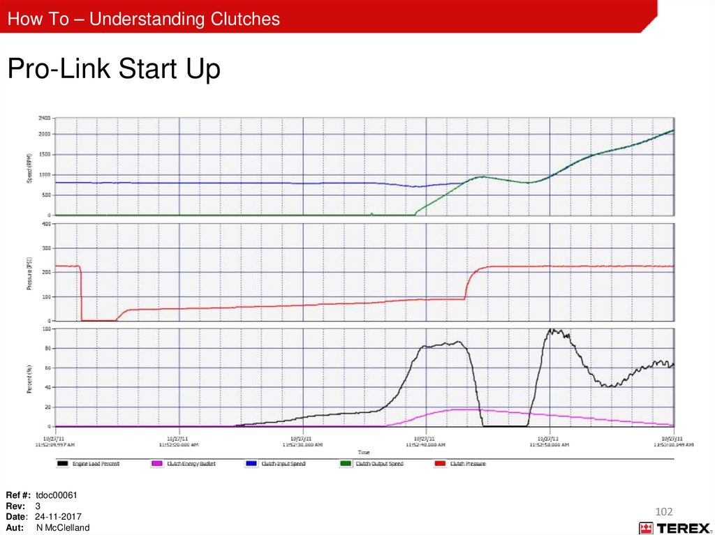
How To – Understanding ClutchesPro-Link Start Up
Ref #: tdoc00061
Rev: 3
Date: 24-11-2017
Aut: N McClelland
102
103.
How To – Understanding ClutchesEngaged
5 AMP
+ 12 Volts
24 Volts
225PSI
PWM Valve
ON/OFF Valve
Ref #: tdoc00061
Rev: 3
Date: 24-11-2017
Aut: N McClelland
GP1 = 400 Psi GP2 =
225 Psi
4 volts
103
104.
How To – Understanding ClutchesDisengaged
5 AMP
+ 12 Volts
24 Volts
225PSI
PWM Valve
Ref #: tdoc00061
Rev: 3
Date: 24-11-2017
Aut: N McClelland
GP1 = 400 Psi GP2 =
225 Psi
4 volts
104
105.
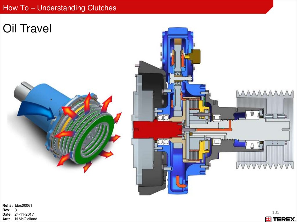
How To – Understanding ClutchesOil Travel
Ref #: tdoc00061
Rev: 3
Date: 24-11-2017
Aut: N McClelland
105
106.
How To – Understanding ClutchesPT Tech 14” Wet – Controller Light Functions
Ref #: tdoc00061
Rev: 3
Date: 24-11-2017
Aut: N McClelland
106
107.
How To – Understanding ClutchesPT Tech 14” Wet – Controller Operating Sequence
Key On:
• Power light ON
• Pressure transducer light ON
• J1939 CAN light ON (if connected)
Ref #: tdoc00061
Rev: 3
Date: 24-11-2017
Aut: N McClelland
107
108.
How To – Understanding ClutchesPT Tech 14” Wet - Controller Operating Sequence
Engine Running, Clutch Disengaged:
• Power light ON
• Pressure transducer light ON
• J1939 CAN light ON (if connected)
• Input speed light ON
• Pressure in ‘GP2’ port of manifold is at least 225 psi (15.5 bar)
Ref #: tdoc00061
Rev: 3
Date: 24-11-2017
Aut: N McClelland
108
109.
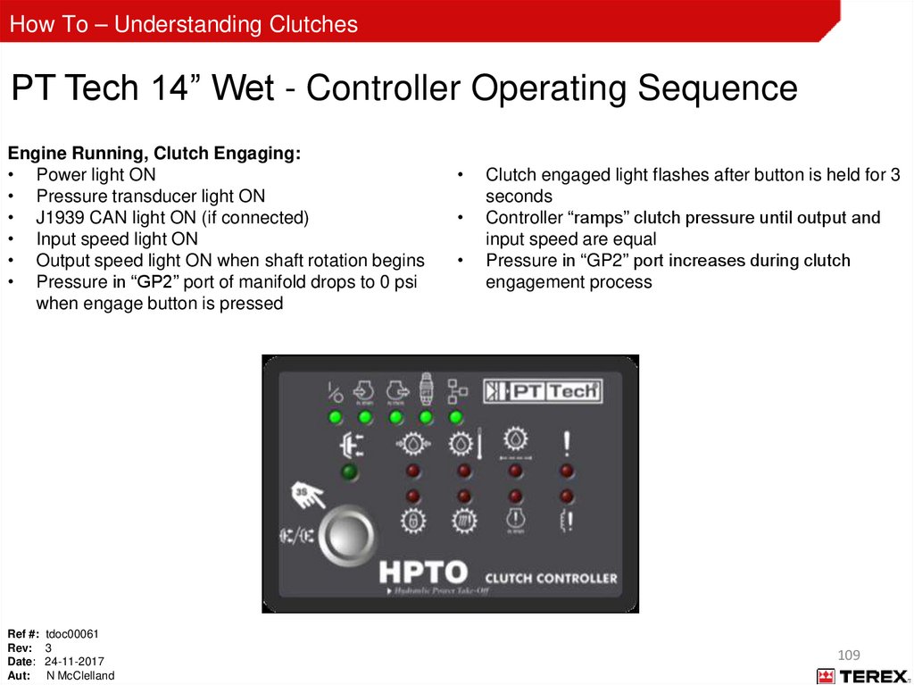
How To – Understanding ClutchesPT Tech 14” Wet - Controller Operating Sequence
Engine Running, Clutch Engaging:
• Power light ON
• Pressure transducer light ON
• J1939 CAN light ON (if connected)
• Input speed light ON
• Output speed light ON when shaft rotation begins
• Pressure in “GP2” port of manifold drops to 0 psi
when engage button is pressed
Ref #: tdoc00061
Rev: 3
Date: 24-11-2017
Aut: N McClelland
Clutch engaged light flashes after button is held for 3
seconds
Controller “ramps” clutch pressure until output and
input speed are equal
Pressure in “GP2” port increases during clutch
engagement process
109
110.
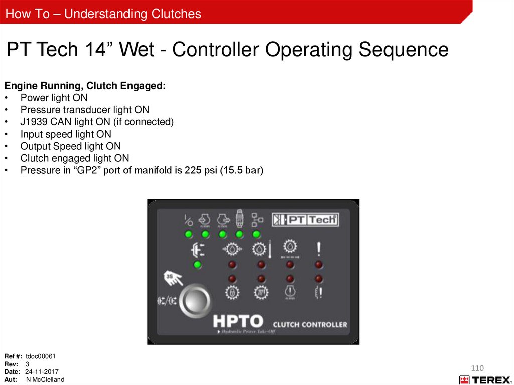
How To – Understanding ClutchesPT Tech 14” Wet - Controller Operating Sequence
Engine Running, Clutch Engaged:
• Power light ON
• Pressure transducer light ON
• J1939 CAN light ON (if connected)
• Input speed light ON
• Output Speed light ON
• Clutch engaged light ON
• Pressure in “GP2” port of manifold is 225 psi (15.5 bar)
Ref #: tdoc00061
Rev: 3
Date: 24-11-2017
Aut: N McClelland
110
111.
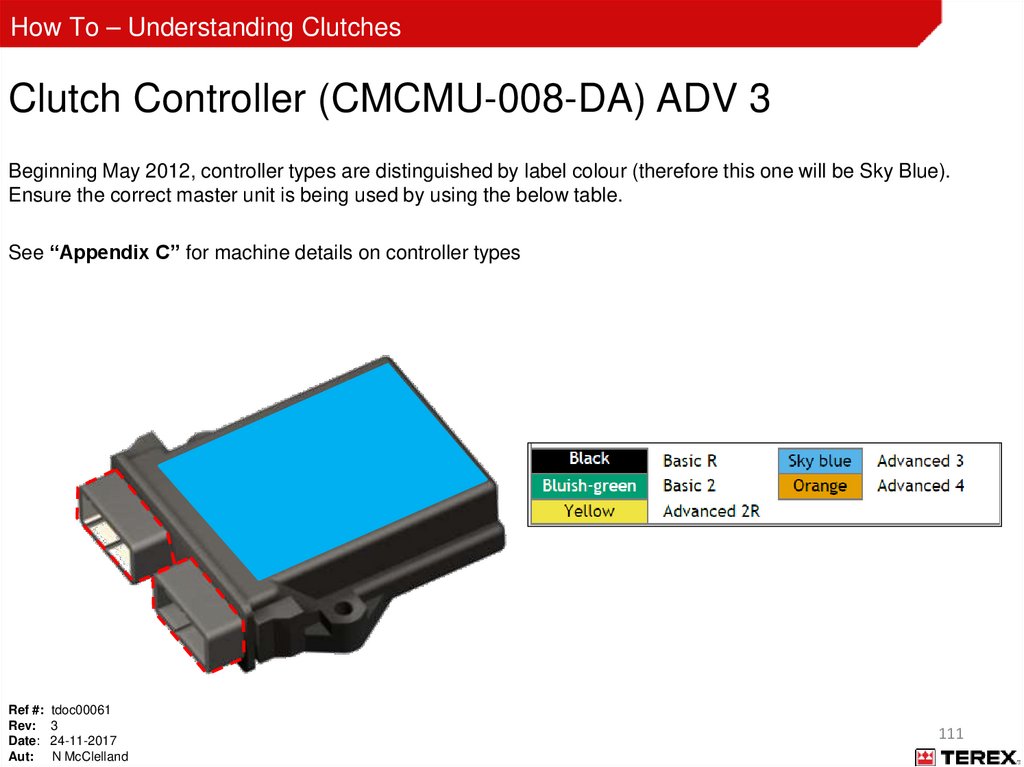
How To – Understanding ClutchesClutch Controller (CMCMU-008-DA) ADV 3
Beginning May 2012, controller types are distinguished by label colour (therefore this one will be Sky Blue).
Ensure the correct master unit is being used by using the below table.
See “Appendix C” for machine details on controller types
Ref #: tdoc00061
Rev: 3
Date: 24-11-2017
Aut: N McClelland
111
112.
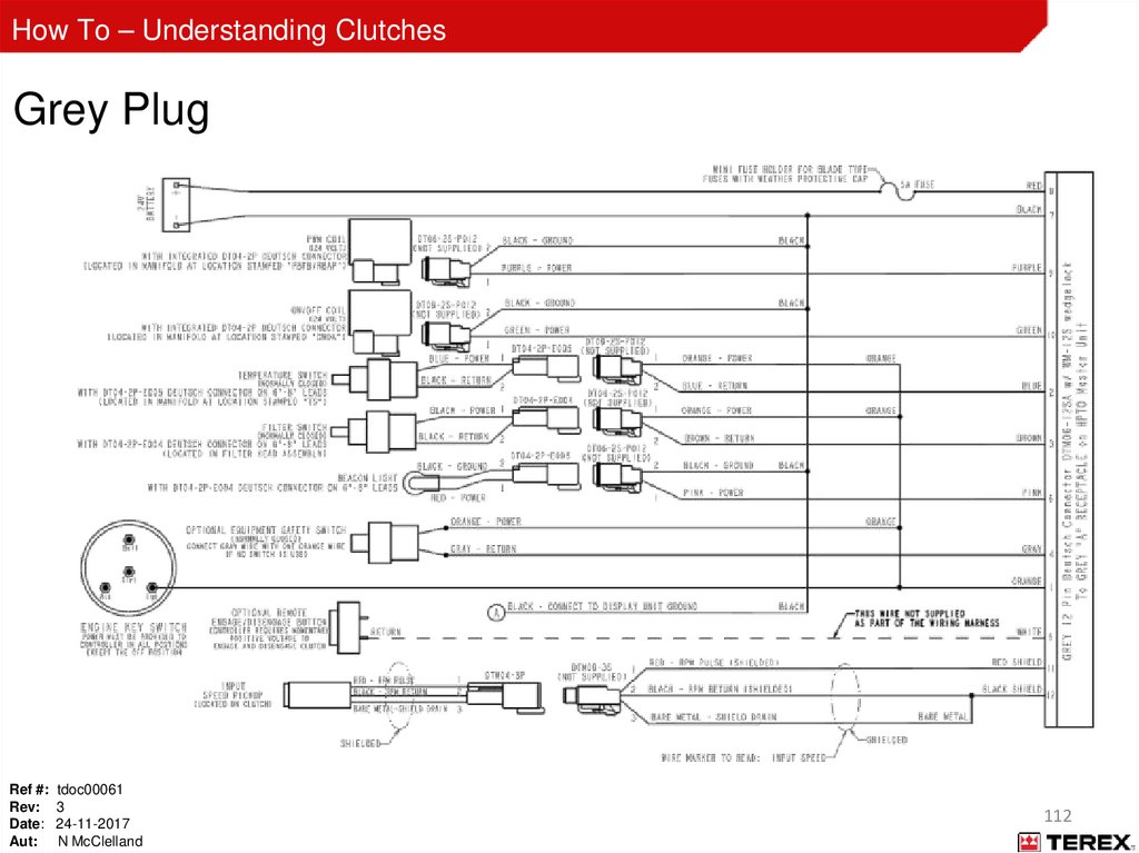
How To – Understanding ClutchesGrey Plug
Ref #: tdoc00061
Rev: 3
Date: 24-11-2017
Aut: N McClelland
112
113.
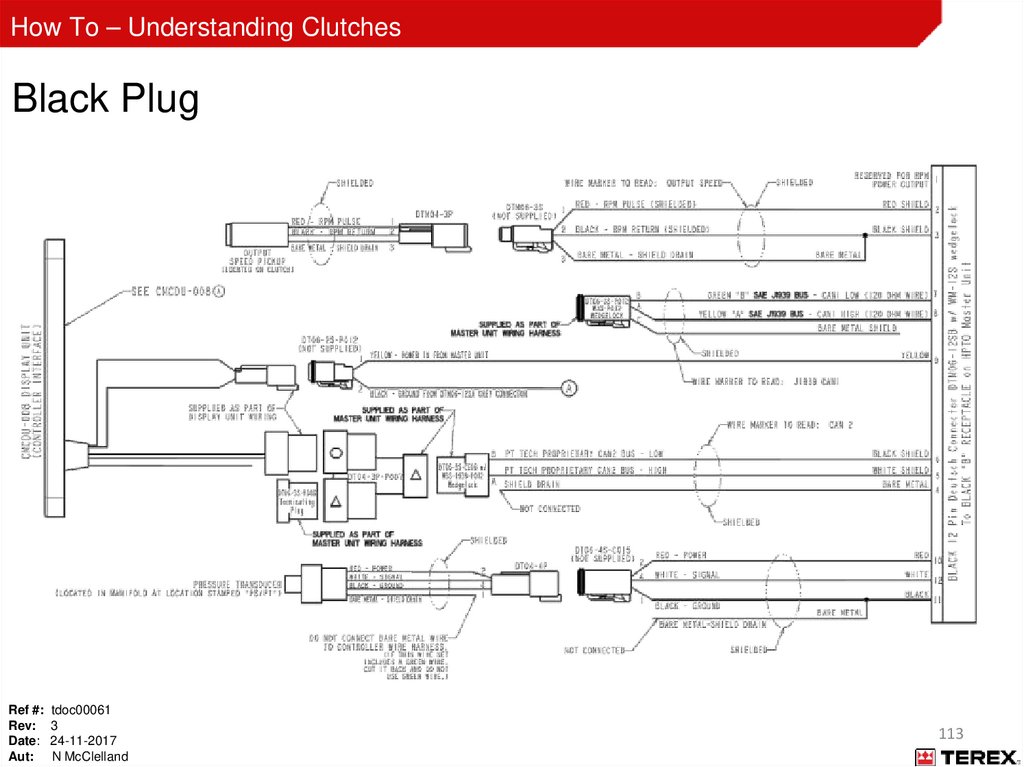
How To – Understanding ClutchesBlack Plug
Ref #: tdoc00061
Rev: 3
Date: 24-11-2017
Aut: N McClelland
113
114.
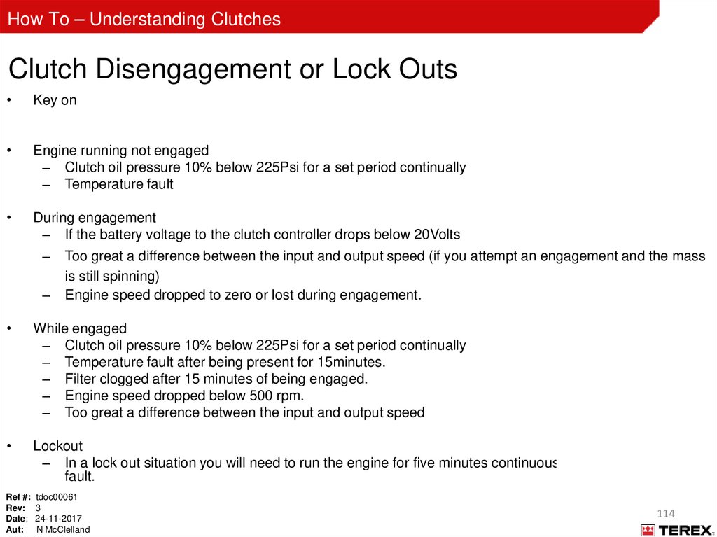
How To – Understanding ClutchesClutch Disengagement or Lock Outs
Key on
– Pressure transducer return voltage is out of range 0.8 to 1.2 volts
Engine running not engaged
– Clutch oil pressure 10% below 225Psi for a set period continually
– Temperature fault
During engagement
– If the battery voltage to the clutch controller drops below 20Volts
–
–
Too great a difference between the input and output speed (if you attempt an engagement and the mass
is still spinning)
Engine speed dropped to zero or lost during engagement.
While engaged
– Clutch oil pressure 10% below 225Psi for a set period continually
– Temperature fault after being present for 15minutes.
– Filter clogged after 15 minutes of being engaged.
– Engine speed dropped below 500 rpm.
– Too great a difference between the input and output speed
Lockout
– In a lock out situation you will need to run the engine for five minutes continuously to clear the lock out
fault.
Ref #: tdoc00061
Rev: 3
Date: 24-11-2017
Aut: N McClelland
114
115.
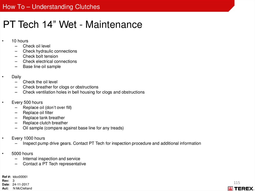
How To – Understanding ClutchesPT Tech 14” Wet - Maintenance
10 hours
– Check oil level
– Check hydraulic connections
– Check bolt tension
– Check electrical connections
– Base line oil sample
Daily
– Check the oil level
– Check breather for clogs or obstructions
– Check ventilation holes in bell housing for clogs and obstructions
Every 500 hours
– Replace oil (don’t over fill)
– Replace oil filter
– Replace tank breather
– Replace clutch breather
– Oil sample (compare against base line for any treads)
Every 1000 hours
– Inspect pump drive gears. Contact PT Tech for inspection procedure and additional information
5000 hours
– Internal inspection and service
– Contact a PT Tech representative
Ref #: tdoc00061
Rev: 3
Date: 24-11-2017
Aut: N McClelland
115
116.
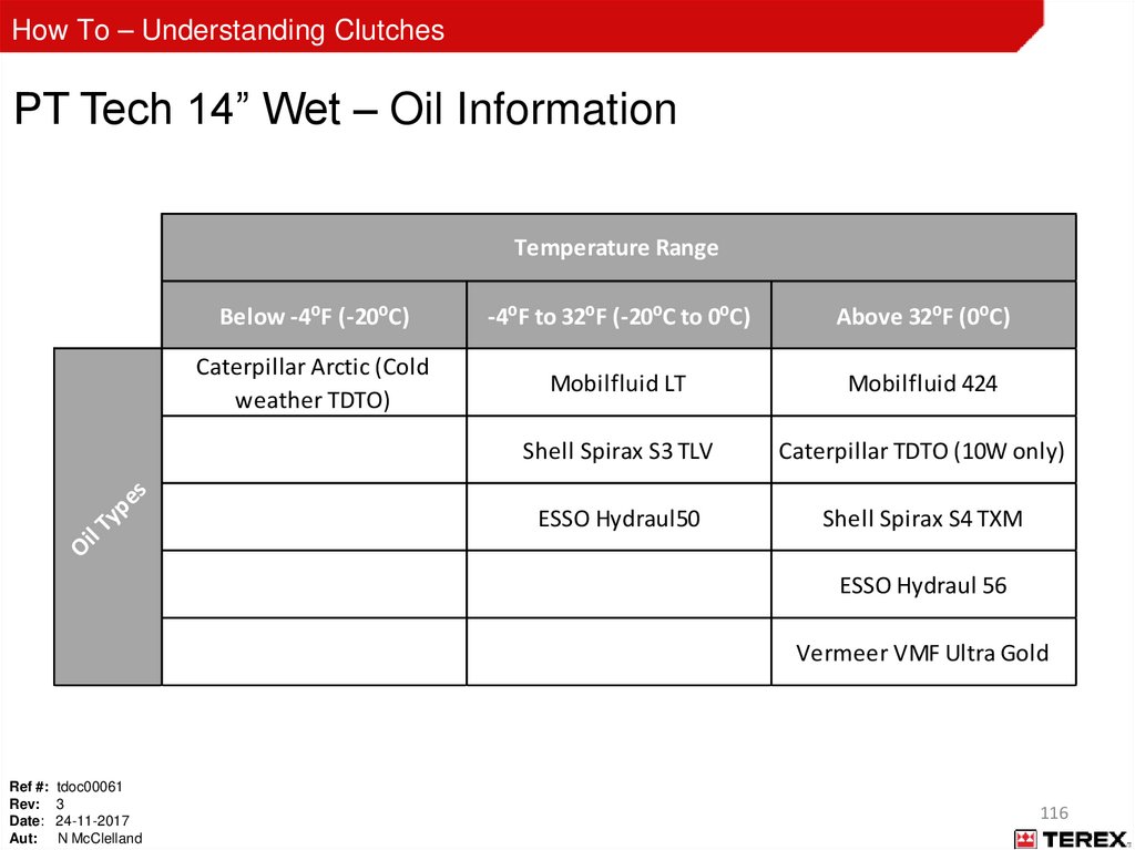
How To – Understanding ClutchesPT Tech 14” Wet – Oil Information
Below -4⁰F (-20⁰C)
-4⁰F to 32⁰F (-20⁰C to 0⁰C)
Above 32⁰F (0⁰C)
Caterpillar Arctic (Cold
weather TDTO)
Mobilfluid LT
Mobilfluid 424
Shell Spirax S3 TLV
Caterpillar TDTO (10W only)
ESSO Hydraul50
Shell Spirax S4 TXM
Oi
l
Ty
pe
s
Temperature Range
ESSO Hydraul 56
Vermeer VMF Ultra Gold
Ref #: tdoc00061
Rev: 3
Date: 24-11-2017
Aut: N McClelland
116
117.
How To – Understanding ClutchesPT Tech 14” Wet – Oil Information
Some signs which show that the wrong type of oil has been used:
Excessive wear on clutch
gears and friction plates due
to wrong oil type.
Ref #: tdoc00061
Rev: 3
Date: 24-11-2017
Aut: N McClelland
117
118.
How To – Understanding ClutchesPT Tech 14” Wet – Oil Information
Ref #: tdoc00061
Rev: 3
Date: 24-11-2017
Aut: N McClelland
118
119.
How To – Understanding ClutchesAppendix A
Troubleshooting using the PT Tech Display
Ref #: tdoc00061
Rev: 3
Date: 24-11-2017
Aut: N McClelland
119
120.
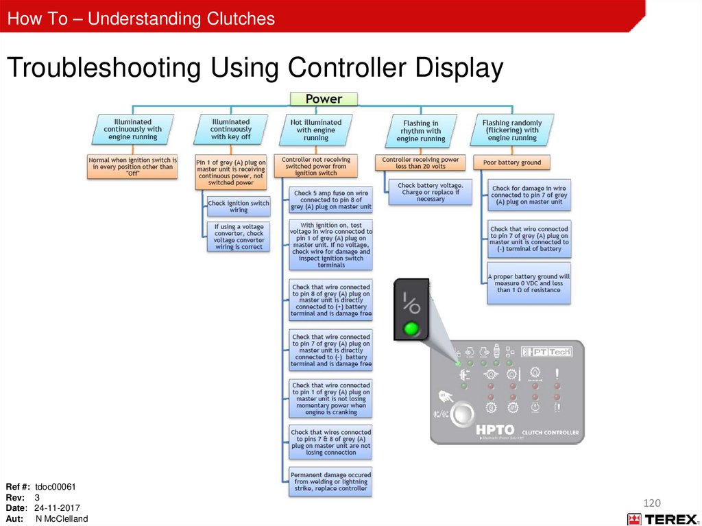
How To – Understanding ClutchesTroubleshooting Using Controller Display
Ref #: tdoc00061
Rev: 3
Date: 24-11-2017
Aut: N McClelland
120
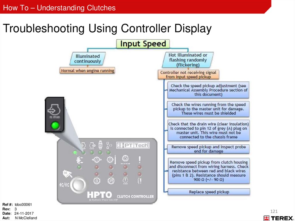
121.
How To – Understanding ClutchesTroubleshooting Using Controller Display
Ref #: tdoc00061
Rev: 3
Date: 24-11-2017
Aut: N McClelland
121
122.
How To – Understanding ClutchesTroubleshooting Using Controller Display
Ref #: tdoc00061
Rev: 3
Date: 24-11-2017
Aut: N McClelland
122
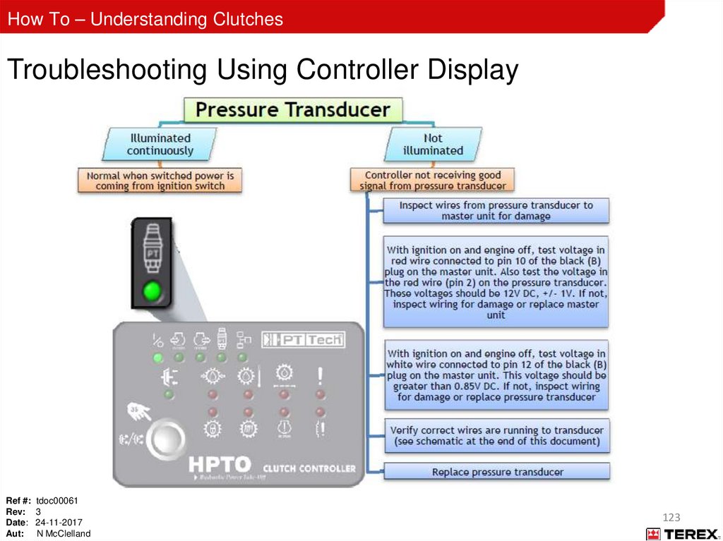
123.
How To – Understanding ClutchesTroubleshooting Using Controller Display
Ref #: tdoc00061
Rev: 3
Date: 24-11-2017
Aut: N McClelland
123
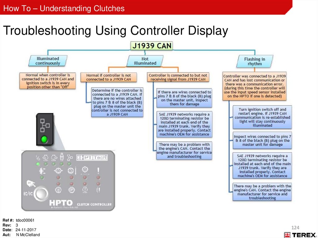
124.
How To – Understanding ClutchesTroubleshooting Using Controller Display
Ref #: tdoc00061
Rev: 3
Date: 24-11-2017
Aut: N McClelland
124
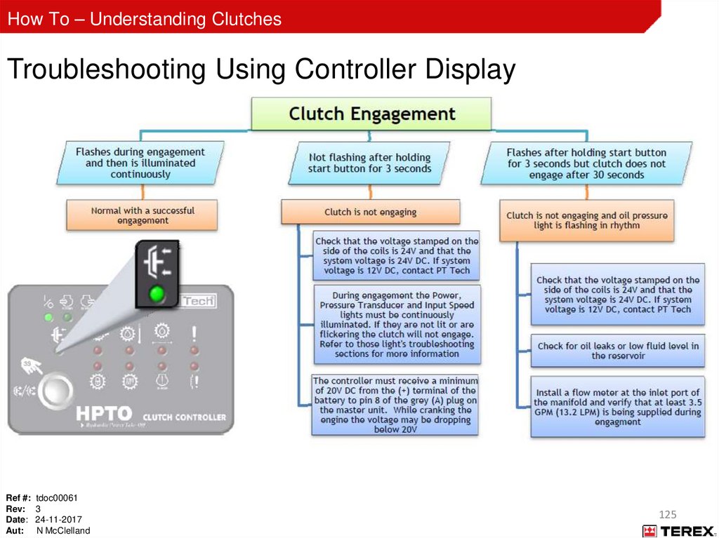
125.
How To – Understanding ClutchesTroubleshooting Using Controller Display
Ref #: tdoc00061
Rev: 3
Date: 24-11-2017
Aut: N McClelland
125
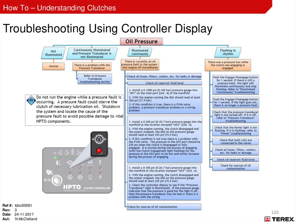
126.
How To – Understanding ClutchesTroubleshooting Using Controller Display
Ref #: tdoc00061
Rev: 3
Date: 24-11-2017
Aut: N McClelland
126
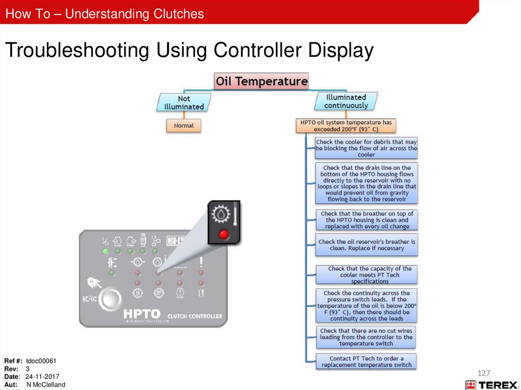
127.
How To – Understanding ClutchesTroubleshooting Using Controller Display
Ref #: tdoc00061
Rev: 3
Date: 24-11-2017
Aut: N McClelland
127
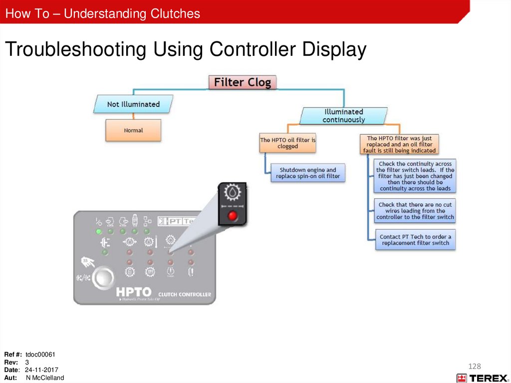
128.
How To – Understanding ClutchesTroubleshooting Using Controller Display
Ref #: tdoc00061
Rev: 3
Date: 24-11-2017
Aut: N McClelland
128
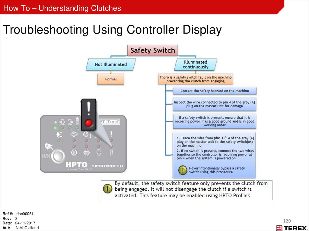
129.
How To – Understanding ClutchesTroubleshooting Using Controller Display
Ref #: tdoc00061
Rev: 3
Date: 24-11-2017
Aut: N McClelland
129
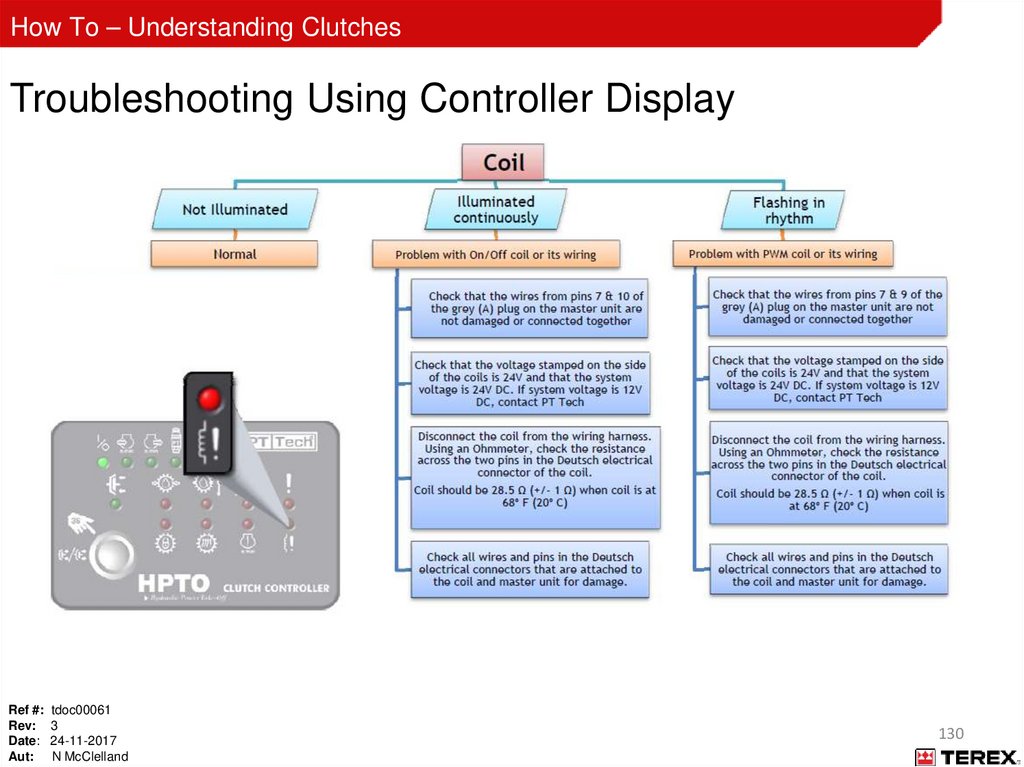
130.
How To – Understanding ClutchesTroubleshooting Using Controller Display
Ref #: tdoc00061
Rev: 3
Date: 24-11-2017
Aut: N McClelland
130
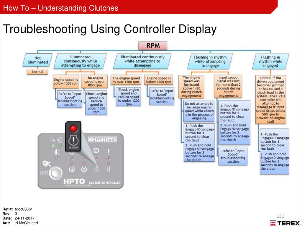
131.
How To – Understanding ClutchesTroubleshooting Using Controller Display
Ref #: tdoc00061
Rev: 3
Date: 24-11-2017
Aut: N McClelland
131
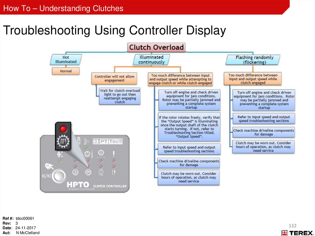
132.
How To – Understanding ClutchesTroubleshooting Using Controller Display
Ref #: tdoc00061
Rev: 3
Date: 24-11-2017
Aut: N McClelland
132
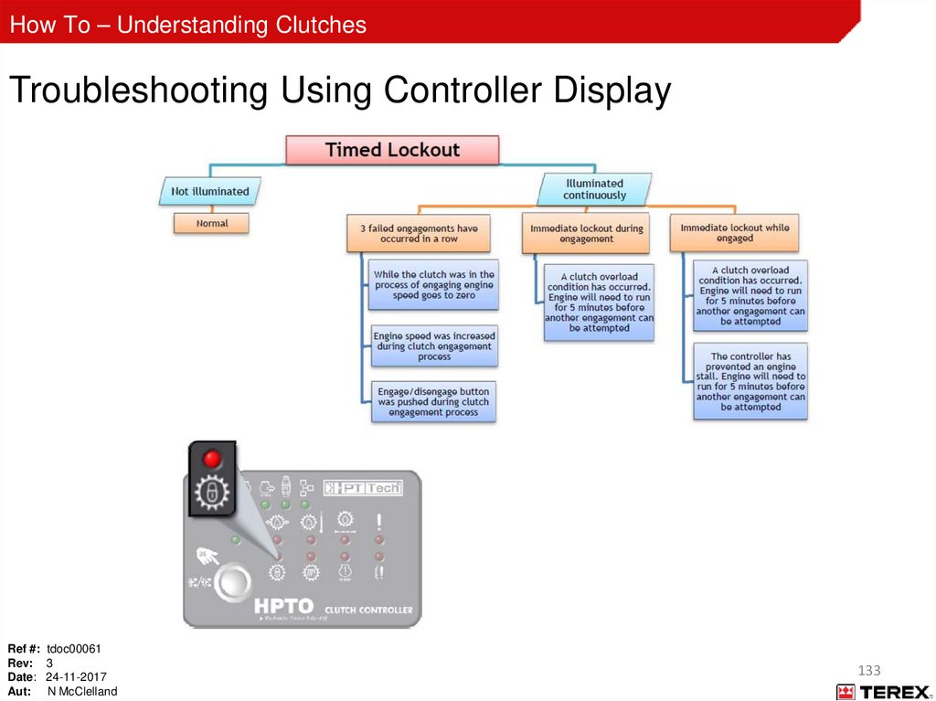
133.
How To – Understanding ClutchesTroubleshooting Using Controller Display
Ref #: tdoc00061
Rev: 3
Date: 24-11-2017
Aut: N McClelland
133
134.
How To – Understanding ClutchesAppendix B
SPN FMI codes
Ref #: tdoc00061
Rev: 3
Date: 24-11-2017
Aut: N McClelland
134
135.
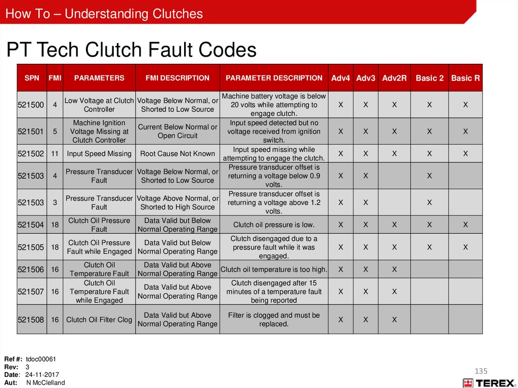
How To – Understanding ClutchesPT Tech Clutch Fault Codes
SPN
FMI
521500
4
521501
5
PARAMETERS
4
521503
3
PARAMETER DESCRIPTION
Machine battery voltage is below
20 volts while attempting to
engage clutch.
Machine Ignition
Input speed detected but no
Current Below Normal or
Voltage Missing at
voltage received from ignition
Open Circuit
Clutch Controller
switch.
Input speed missing while
Input Speed Missing Root Cause Not Known
attempting to engage the clutch.
Pressure transducer offset is
Pressure Transducer Voltage Below Normal, or
returning a voltage below 0.9
Fault
Shorted to Low Source
volts.
Pressure transducer offset is
Pressure Transducer Voltage Above Normal, or
returning a voltage above 1.2
Fault
Shorted to High Source
volts.
Clutch Oil Pressure
Data Valid but Below
Clutch oil pressure is low.
Fault
Normal Operating Range
Clutch disengaged due to a
Clutch Oil Pressure
Data Valid but Below
pressure fault while it was
Fault while Engaged Normal Operating Range
engaged.
Clutch Oil
Data Valid but Above
Clutch oil temperature is too high.
Temperature Fault Normal Operating Range
Clutch Oil
Clutch disengaged after 15
Data Valid but Above
Temperature Fault
minutes of a temperature fault
Normal Operating Range
while Engaged
being reported
Low Voltage at Clutch Voltage Below Normal, or
Controller
Shorted to Low Source
521502 11
521503
FMI DESCRIPTION
521504 18
521505 18
521506 16
521507 16
Data Valid but Above
521508 16 Clutch Oil Filter Clog Normal Operating Range
Ref #: tdoc00061
Rev: 3
Date: 24-11-2017
Aut: N McClelland
Filter is clogged and must be
replaced.
Adv4 Adv3 Adv2R
Basic 2 Basic R
X
X
X
X
X
X
X
X
X
X
X
X
X
X
X
X
X
X
X
X
X
X
X
X
X
X
X
X
X
X
X
X
X
X
X
X
X
X
X
X
135
136.
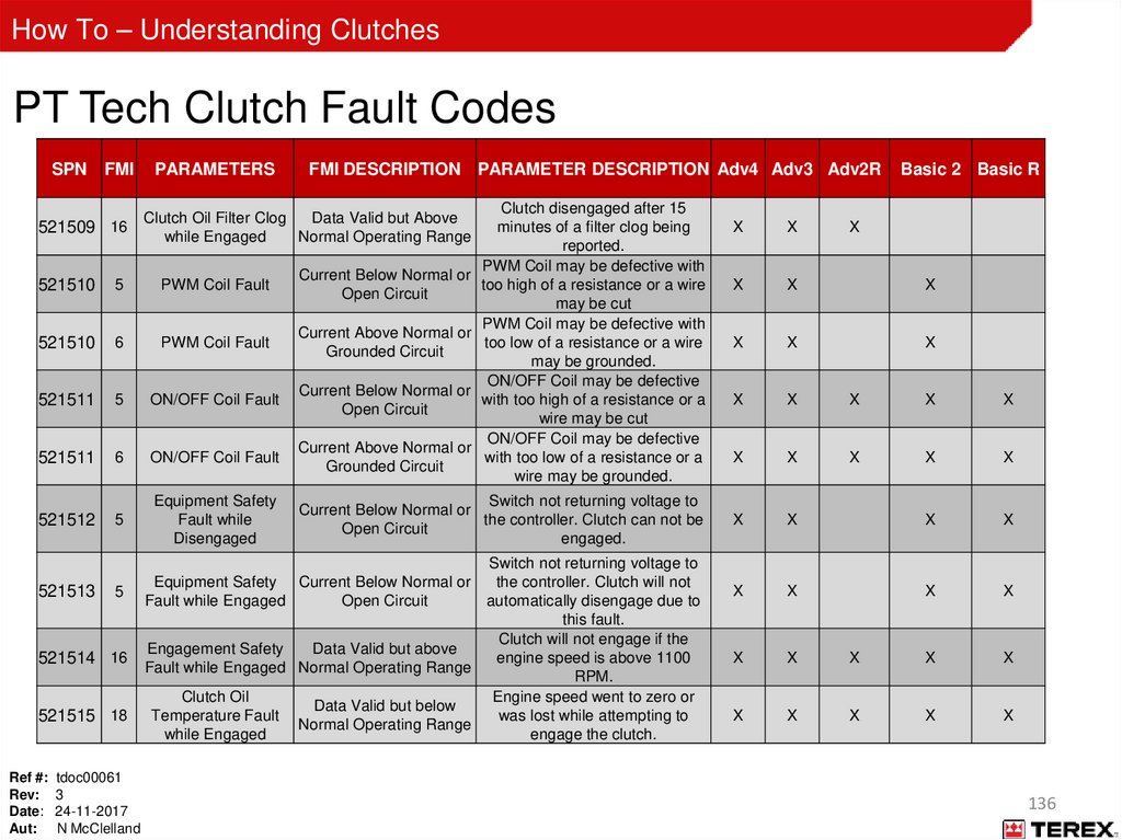
How To – Understanding ClutchesPT Tech Clutch Fault Codes
SPN FMI
521509 16
PARAMETERS
FMI DESCRIPTION PARAMETER DESCRIPTION Adv4 Adv3 Adv2R
Clutch disengaged after 15
minutes of a filter clog being
reported.
PWM Coil may be defective with
Current Below Normal or
too high of a resistance or a wire
Open Circuit
may be cut
PWM Coil may be defective with
Current Above Normal or
too low of a resistance or a wire
Grounded Circuit
may be grounded.
ON/OFF Coil may be defective
Current Below Normal or
with too high of a resistance or a
Open Circuit
wire may be cut
ON/OFF Coil may be defective
Current Above Normal or
with too low of a resistance or a
Grounded Circuit
wire may be grounded.
Clutch Oil Filter Clog
Data Valid but Above
while Engaged
Normal Operating Range
521510
5
PWM Coil Fault
521510
6
PWM Coil Fault
521511
5
ON/OFF Coil Fault
521511
6
ON/OFF Coil Fault
521512
5
Equipment Safety
Fault while
Disengaged
5
Equipment Safety Current Below Normal or
Fault while Engaged
Open Circuit
521513
521514 16
521515 18
Ref #: tdoc00061
Rev: 3
Date: 24-11-2017
Aut: N McClelland
Switch not returning voltage to
Current Below Normal or
the controller. Clutch can not be
Open Circuit
engaged.
Switch not returning voltage to
the controller. Clutch will not
automatically disengage due to
this fault.
Clutch will not engage if the
Engagement Safety
Data Valid but above
engine speed is above 1100
Fault while Engaged Normal Operating Range
RPM.
Clutch Oil
Engine speed went to zero or
Data Valid but below
Temperature Fault
was lost while attempting to
Normal Operating Range
while Engaged
engage the clutch.
Basic 2 Basic R
X
X
X
X
X
X
X
X
X
X
X
X
X
X
X
X
X
X
X
X
X
X
X
X
X
X
X
X
X
X
X
X
X
X
X
X
X
136
137.
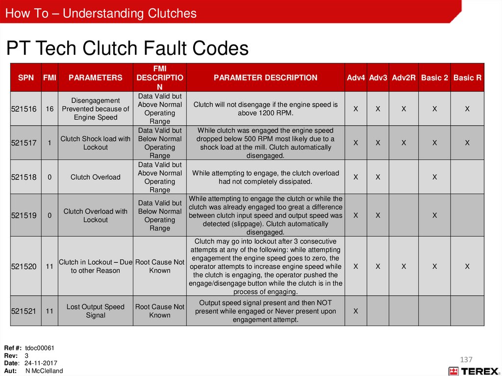
How To – Understanding ClutchesPT Tech Clutch Fault Codes
SPN
FMI
PARAMETERS
16
Disengagement
Prevented because of
Engine Speed
521517
1
Clutch Shock load with
Lockout
521518
0
Clutch Overload
521516
521519
521520
521521
FMI
DESCRIPTIO
N
Data Valid but
Above Normal
Operating
Range
Data Valid but
Below Normal
Operating
Range
Data Valid but
Above Normal
Operating
Range
PARAMETER DESCRIPTION
Clutch will not disengage if the engine speed is
above 1200 RPM.
X
X
X
X
X
While clutch was engaged the engine speed
dropped below 500 RPM most likely due to a
shock load at the mill. Clutch automatically
disengaged.
X
X
X
X
X
While attempting to engage, the clutch overload
had not completely dissipated.
X
X
X
X
X
X
X
X
While attempting to engage the clutch or while the
clutch was already engaged too great a difference
Clutch Overload with
0
between clutch input speed and output speed was
Lockout
detected (slippage). Clutch automatically
disengaged.
Clutch may go into lockout after 3 consecutive
attempts at any of the following: while attempting
engagement the engine speed goes to zero, the
Clutch in Lockout – Due Root Cause Not
11
operator attempts to increase engine speed while
to other Reason
Known
the clutch is engaging, the operator pushed the
engage/disengage button while the clutch is in the
process of engaging.
Data Valid but
Below Normal
Operating
Range
11
Ref #: tdoc00061
Rev: 3
Date: 24-11-2017
Aut: N McClelland
Lost Output Speed
Signal
Root Cause Not
Known
Adv4 Adv3 Adv2R Basic 2 Basic R
Output speed signal present and then NOT
present while engaged or Never present upon
engagement attempt.
X
X
X
X
137
138.
How To – Understanding ClutchesAppendix C
Machine Types Vs Controller types
Ref #: tdoc00061
Rev: 3
Date: 24-11-2017
Aut: N McClelland
138
139.
How To – Understanding ClutchesRef #: tdoc00061
Rev: 3
Date: 24-11-2017
Aut: N McClelland
139
140.
How To – Understanding ClutchesAppendix D
Desch Revox clutch
Ref #: tdoc00061
Rev: 3
Date: 24-11-2017
Aut: N McClelland
140
141.
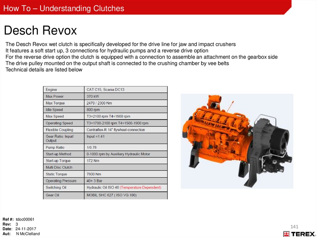
How To – Understanding ClutchesDesch Revox
The Desch Revox wet clutch is specifically developed for the drive line for jaw and impact crushers
It features a soft start up, 3 connections for hydraulic pumps and a reverse drive option
For the reverse drive option the clutch is equipped with a connection to assemble an attachment on the gearbox side
The drive pulley mounted on the output shaft is connected to the crushing chamber by vee belts
Technical details are listed below
Ref #: tdoc00061
Rev: 3
Date: 24-11-2017
Aut: N McClelland
141
142.
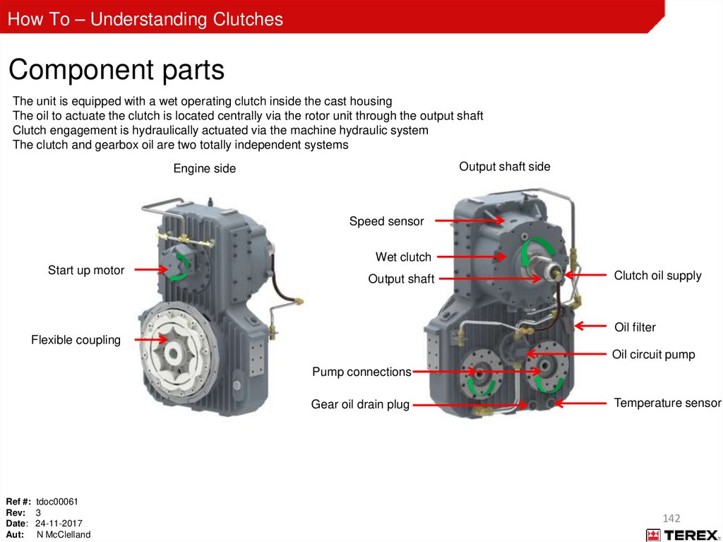
How To – Understanding ClutchesComponent parts
The unit is equipped with a wet operating clutch inside the cast housing
The oil to actuate the clutch is located centrally via the rotor unit through the output shaft
Clutch engagement is hydraulically actuated via the machine hydraulic system
The clutch and gearbox oil are two totally independent systems
Output shaft side
Engine side
Speed sensor
Wet clutch
Start up motor
Output shaft
Clutch oil supply
Oil filter
Flexible coupling
Oil circuit pump
Pump connections
Gear oil drain plug
Ref #: tdoc00061
Rev: 3
Date: 24-11-2017
Aut: N McClelland
Temperature sensor
142
143.
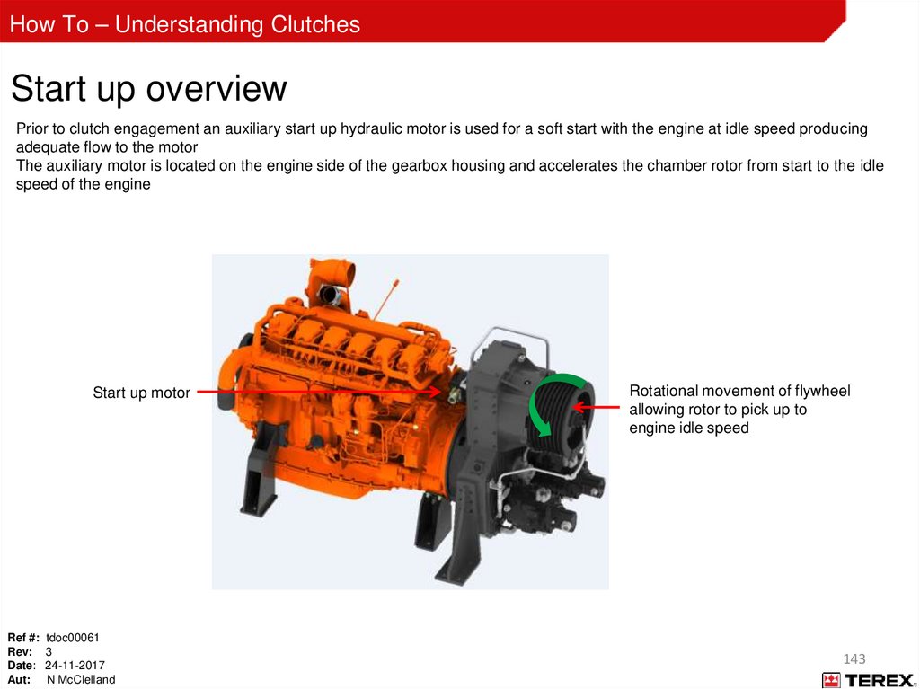
How To – Understanding ClutchesStart up overview
Prior to clutch engagement an auxiliary start up hydraulic motor is used for a soft start with the engine at idle speed producing
adequate flow to the motor
The auxiliary motor is located on the engine side of the gearbox housing and accelerates the chamber rotor from start to the idle
speed of the engine
Start up motor
Ref #: tdoc00061
Rev: 3
Date: 24-11-2017
Aut: N McClelland
Rotational movement of flywheel
allowing rotor to pick up to
engine idle speed
143
144.
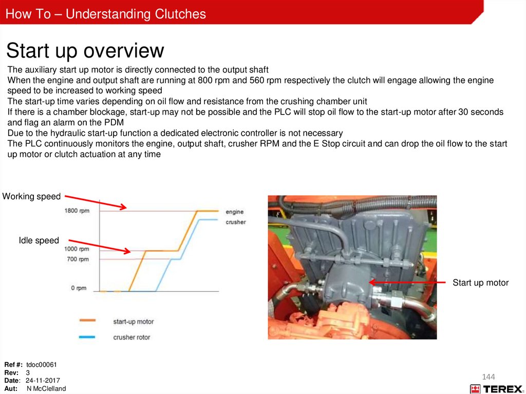
How To – Understanding ClutchesStart up overview
The auxiliary start up motor is directly connected to the output shaft
When the engine and output shaft are running at 800 rpm and 560 rpm respectively the clutch will engage allowing the engine
speed to be increased to working speed
The start-up time varies depending on oil flow and resistance from the crushing chamber unit
If there is a chamber blockage, start-up may not be possible and the PLC will stop oil flow to the start-up motor after 30 seconds
and flag an alarm on the PDM
Due to the hydraulic start-up function a dedicated electronic controller is not necessary
The PLC continuously monitors the engine, output shaft, crusher RPM and the E Stop circuit and can drop the oil flow to the start
up motor or clutch actuation at any time
Working speed
Idle speed
Start up motor
Ref #: tdoc00061
Rev: 3
Date: 24-11-2017
Aut: N McClelland
144
145.
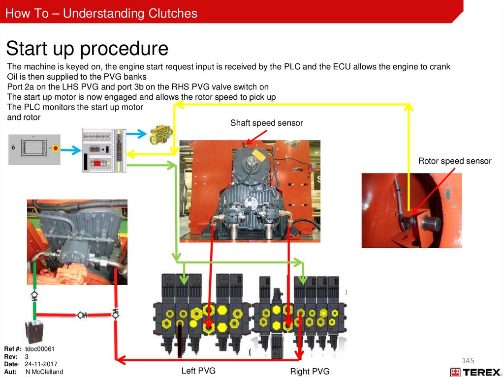
How To – Understanding ClutchesStart up procedure
The machine is keyed on, the engine start request input is received by the PLC and the ECU allows the engine to crank
Oil is then supplied to the PVG banks
Port 2a on the LHS PVG and port 3b on the RHS PVG valve switch on
The start up motor is now engaged and allows the rotor speed to pick up
The PLC monitors the start up motor
and rotor
Shaft speed sensor
Rotor speed sensor
Ref #: tdoc00061
Rev: 3
Date: 24-11-2017
Aut: N McClelland
145
Left PVG
Right PVG
146.
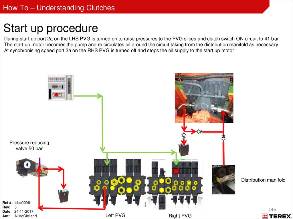
How To – Understanding ClutchesStart up procedure
During start up port 2a on the LHS PVG is turned on to raise pressures to the PVG slices and clutch switch ON circuit to 41 bar
The start up motor becomes the pump and re circulates oil around the circuit taking from the distribution manifold as necessary
At synchronising speed port 3a on the RHS PVG is turned off and stops the oil supply to the start up motor
Pressure reducing
valve 50 bar
Distribution manifold
Ref #: tdoc00061
Rev: 3
Date: 24-11-2017
Aut: N McClelland
146
Left PVG
Right PVG
147.
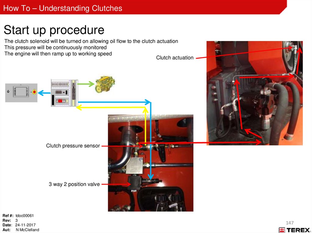
How To – Understanding ClutchesStart up procedure
The clutch solenoid will be turned on allowing oil flow to the clutch actuation
This pressure will be continuously monitored
The engine will then ramp up to working speed
Clutch actuation
Clutch pressure sensor
3 way 2 position valve
Ref #: tdoc00061
Rev: 3
Date: 24-11-2017
Aut: N McClelland
147
148.
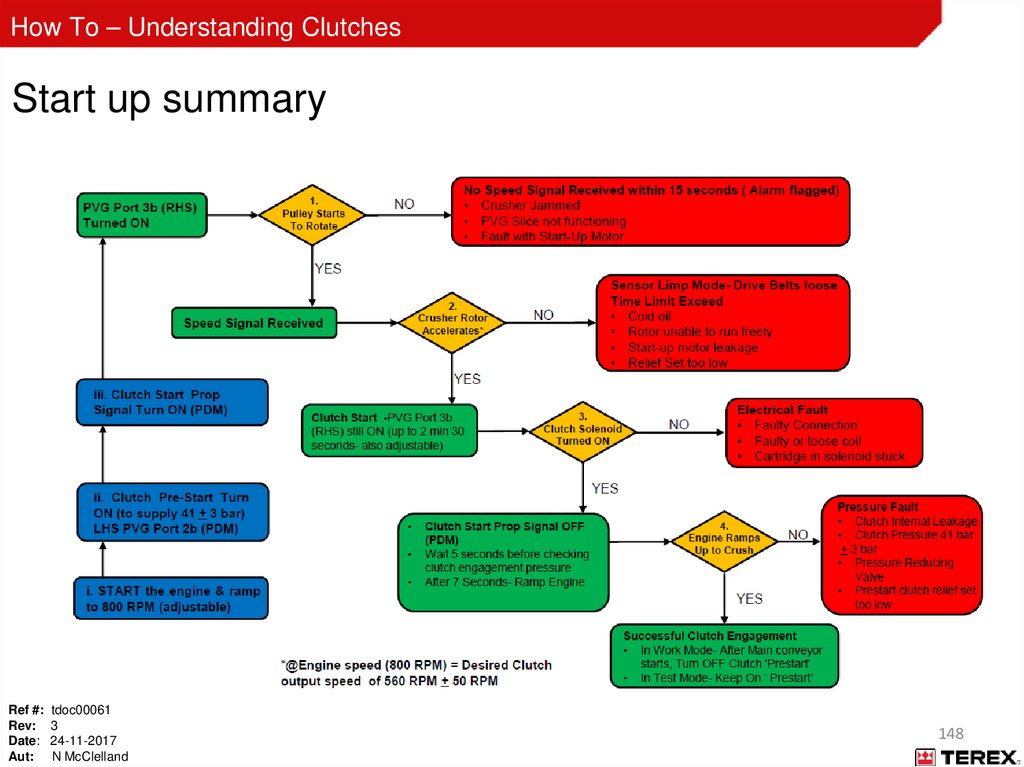
How To – Understanding ClutchesStart up summary
Ref #: tdoc00061
Rev: 3
Date: 24-11-2017
Aut: N McClelland
148
149.
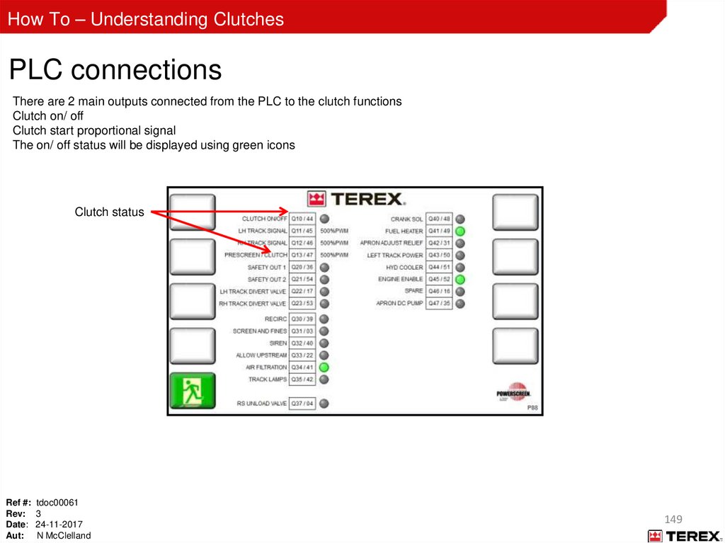
How To – Understanding ClutchesPLC connections
There are 2 main outputs connected from the PLC to the clutch functions
Clutch on/ off
Clutch start proportional signal
The on/ off status will be displayed using green icons
Clutch status
Ref #: tdoc00061
Rev: 3
Date: 24-11-2017
Aut: N McClelland
149
150.
How To – Understanding ClutchesPLC connections
The clutch start signal allows the oil flow to the start up motor to take the rotor from idle to clutch engagement speed
The output power is sent from Node 1
The PWM signal is sent from the PLC
These are sent via the hydraulic cabinet harness to the solenoid of slice 3 on the PVG
The ramp up time can be adjusted by the user ( top level password required)
The desired clutch output speed is calculated using a 0.7 ratio ( engine to clutch speed)
The on/ off solenoid switches on to allow oil to be diverted to engage the clutch once ramp up/ synchronisation success
Hydraulic
cabinet
harness
Ref #: tdoc00061
Rev: 3
Date: 24-11-2017
Aut: N McClelland
Clutch on/off
solenoid
Clutch start signal
RHS valve bank
150
151.
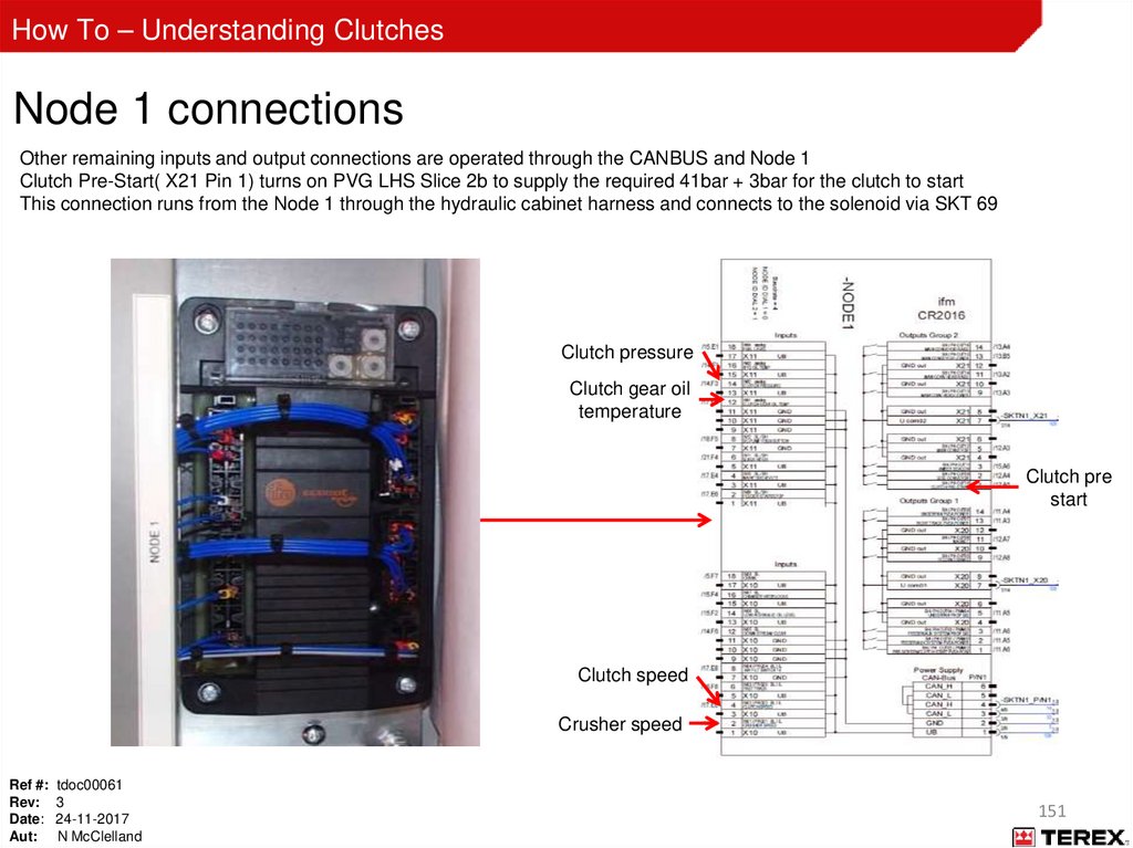
How To – Understanding ClutchesNode 1 connections
Other remaining inputs and output connections are operated through the CANBUS and Node 1
Clutch Pre-Start( X21 Pin 1) turns on PVG LHS Slice 2b to supply the required 41bar + 3bar for the clutch to start
This connection runs from the Node 1 through the hydraulic cabinet harness and connects to the solenoid via SKT 69
Clutch pressure
Clutch gear oil
temperature
Clutch pre
start
Clutch speed
Crusher speed
Ref #: tdoc00061
Rev: 3
Date: 24-11-2017
Aut: N McClelland
151
152.
How To – Understanding ClutchesNode 1 connections
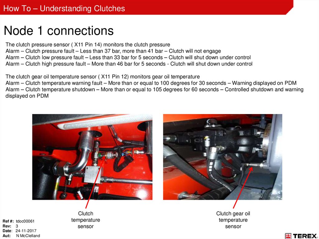
The clutch pressure sensor ( X11 Pin 14) monitors the clutch pressure
Alarm – Clutch pressure fault – Less than 37 bar, more than 41 bar – Clutch will not engage
Alarm – Clutch low pressure fault – Less than 33 bar for 5 seconds – Clutch will shut down under control
Alarm – Clutch high pressure fault – More than 46 bar for 5 seconds - Clutch will shut down under control
The clutch gear oil temperature sensor ( X11 Pin 12) monitors gear oil temperature
Alarm – Clutch temperature warning fault – More than or equal to 100 degrees for 30 seconds – Warning displayed on PDM
Alarm – Clutch temperature shutdown – More than or equal to 105 degrees for 60 seconds – Controlled shutdown and warning
displayed on PDM
Ref #: tdoc00061
Rev: 3
Date: 24-11-2017
Aut: N McClelland
Clutch
temperature
sensor
Clutch gear oil
temperature
sensor
153.
How To – Understanding ClutchesNode 1 connections
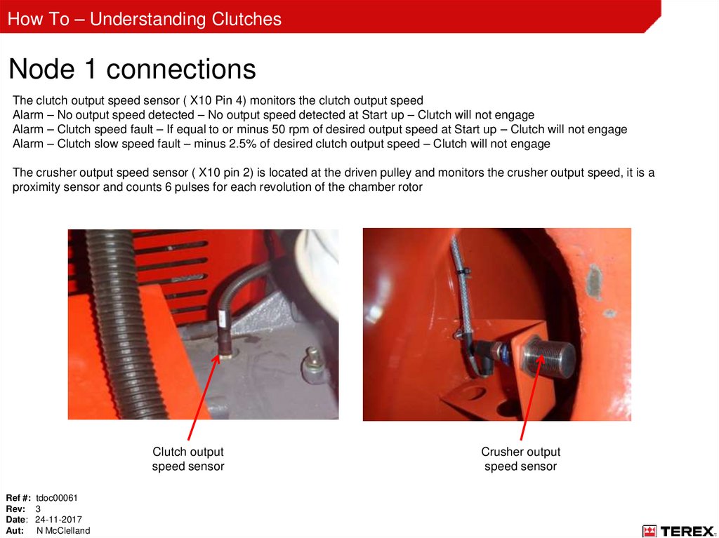
The clutch output speed sensor ( X10 Pin 4) monitors the clutch output speed
Alarm – No output speed detected – No output speed detected at Start up – Clutch will not engage
Alarm – Clutch speed fault – If equal to or minus 50 rpm of desired output speed at Start up – Clutch will not engage
Alarm – Clutch slow speed fault – minus 2.5% of desired clutch output speed – Clutch will not engage
The crusher output speed sensor ( X10 pin 2) is located at the driven pulley and monitors the crusher output speed, it is a
proximity sensor and counts 6 pulses for each revolution of the chamber rotor
Clutch output
speed sensor
Ref #: tdoc00061
Rev: 3
Date: 24-11-2017
Aut: N McClelland
Crusher output
speed sensor
154.
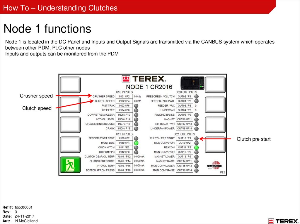
How To – Understanding ClutchesNode 1 functions
Node 1 is located in the DC Panel and Inputs and Output Signals are transmitted via the CANBUS system which operates
between other PDM, PLC other nodes
Inputs and outputs can be monitored from the PDM
Crusher speed
Clutch speed
Clutch pre start
Ref #: tdoc00061
Rev: 3
Date: 24-11-2017
Aut: N McClelland