


 mechanics
Similar presentations:


 - Technical Highlights")

AMT Technical Training. Automatic Mechanical Transmission
1.
AMT Technical TrainingAutomatic Mechanical Transmission
Sandy · Mar, 2010
After-sale Service Department
1
2.
1.The course will take you approx 45 minutes2.Please linsten carefully,and we will have a test
3.Please refer to the remarks at the bottom
4.Keep your cellphone on mute condition
3.
CatalogSystem overview
Basic principle
System specification
Components
Service standard
Trouble-shooting and solutions
4.
System overview5.
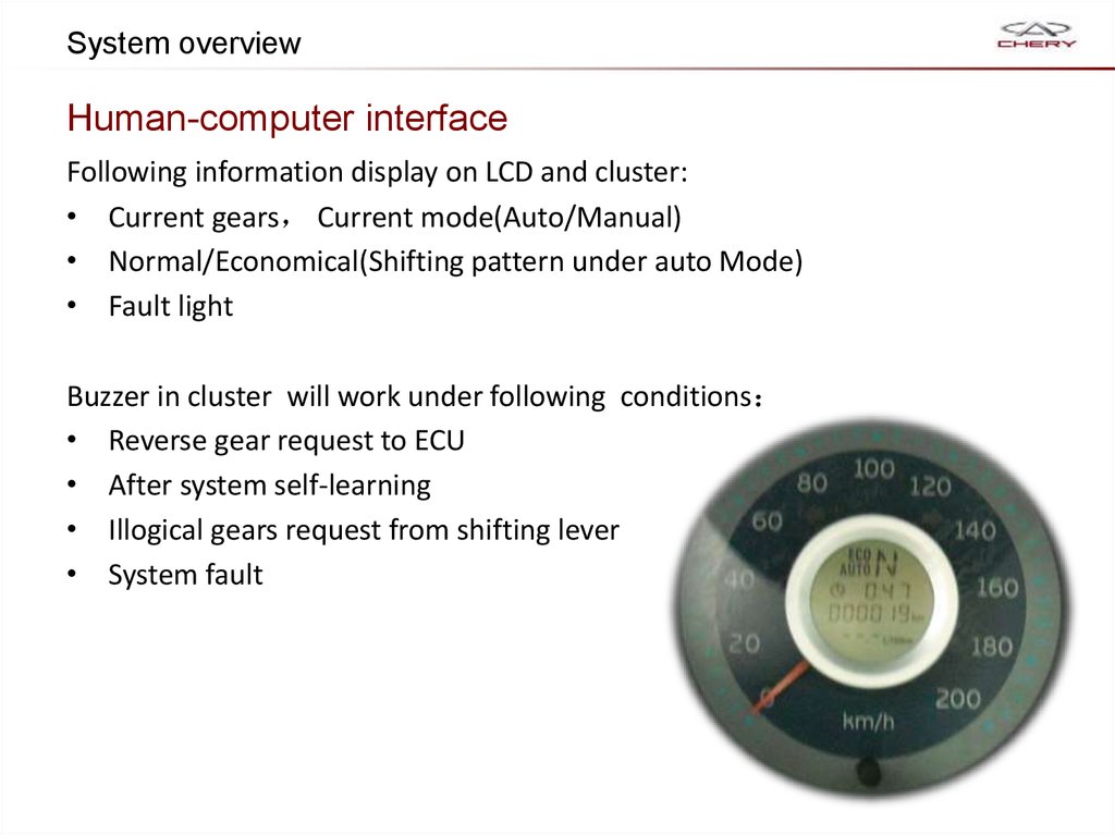
System overviewHuman-computer interface
Following information display on LCD and cluster:
• Current gears Current mode(Auto/Manual)
• Normal/Economical(Shifting pattern under auto Mode)
• Fault light
Buzzer in cluster will work under following conditions
• Reverse gear request to ECU
• After system self-learning
• Illogical gears request from shifting lever
• System fault
6. System layout
ECU2 Electrohydraulic unit
Econ/Norm button brake switch
TCU
Shift lever
4 Cluster
Accelerator
7. System introduction
1. On the basis of the original manual transmission gearbox and clutch to addauxiliary hydraulic power control unit , Which retains all the advantages of clutch
and mechanical gearbox (weight, strength and reliability, low power consumption),
and to have automatic transmission.
2. Eliminated clutch pedal and shift wires, gear lever machines were replaced by an
electronic joystick marked with (+/-/ N / R) reduce costs, improve the system
reliability.
3. Improved user interface, less operation to improve the driving safety , especially in
urban conditions.
4. Shifting point will alter with the vehicle and driver’s willing.
8.
System introductionShift lever
Manual semi-auto mode
Automatic(Eco)
Automatic(Norm)
Shift lever position with three
stable and three unstable position,
the position signal was
transformed by the Hall sensor
into electrical signals.
9.
System introductionShift to Neutral during running
APP sensor
released
Vehicle
speed
<80KM/H
requirement
10.
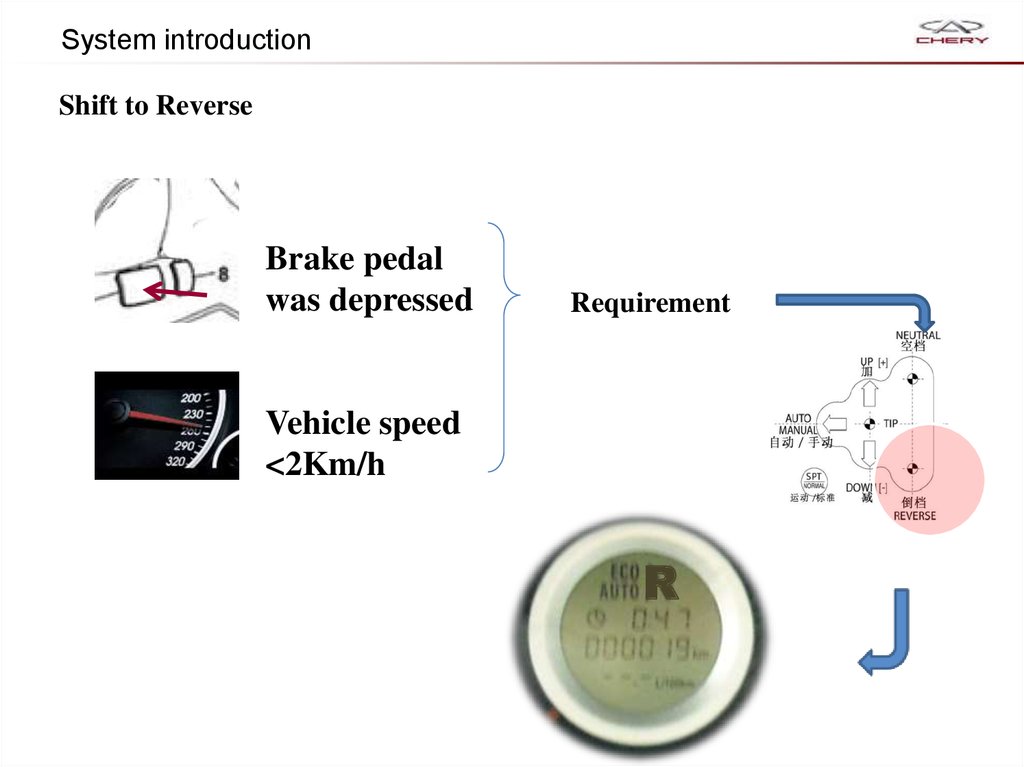
System introductionShift to Reverse
Brake pedal
was depressed
Requirement
Vehicle speed
<2Km/h
R
11.
System introductionShift lever instructions
Possible following situation may cause when the driver try to move shift lever
without depressing the brake pedal.
Transmission
engaged in
LCD
displays
Shift lever final
position
buzzer
Fault light
Neutral
[N]
TIP
On
Off
Reverse
[R]
TIP
On
Off
Reverse
[R]
Neutral
On
Off
A gears
[A]
Neutral
On
Off
Neutral
[N]
Reverse
On
Off
A Gears
[A]
Reverse
On
Off
System will automatically switch to Neutral gear once the driver’s door
opens
12. Knowledge prepration
Clutchrelease fork
Engage
direction
Select
direction
Three types of operation on transmission are replace by Actuator ( Electrohydraulic
mechanism )
13. Electrohydraulic Mechanism
14.
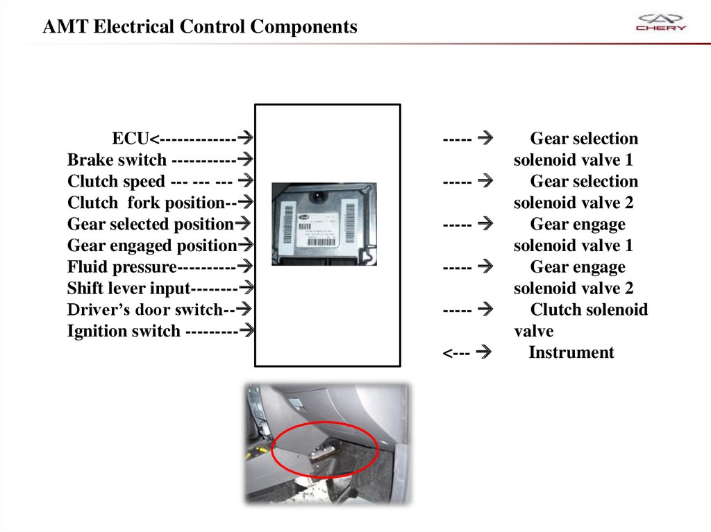
AMT Electrical Control ComponentsECU<-------------
Brake switch -----------
Clutch speed --- --- ---
Clutch fork position--
Gear selected position
Gear engaged position
Fluid pressure----------
Shift lever input--------
Driver’s door switch--
Ignition switch ---------
-----
-----
-----
-----
-----
<---
Gear selection
solenoid valve 1
Gear selection
solenoid valve 2
Gear engage
solenoid valve 1
Gear engage
solenoid valve 2
Clutch solenoid
valve
Instrument
15. Input signal
APP sensorVehicle speed
sensor
Coolant
temperature
sensor
Engine speed
sensor
Brake
switch
Mode
switch(M/A)
Econ/Norm
button
Shift
Up/down(+/-)
switch
TCU
16. Input signal
Gear engageposition sensor
Driver door
switch
Gear selection
sensor
Ignition switch
Clutch fork
position sensor
TCU
Fluid pressure
sensor
Friction disc speed sensor of
Clutch
17. Output signal
1-2 gearsselection
solenoid
valve(EV3)
5-R gears
selection
solenoid
valve(EV4)
Clutch
solenoid
valve(EV0)
TCU
Relay of
pump
Even gears
engage
solenoid
valve(EV2)
Odd gears
engage
solenoid
valve(EV1)
53
18.
System specification19.
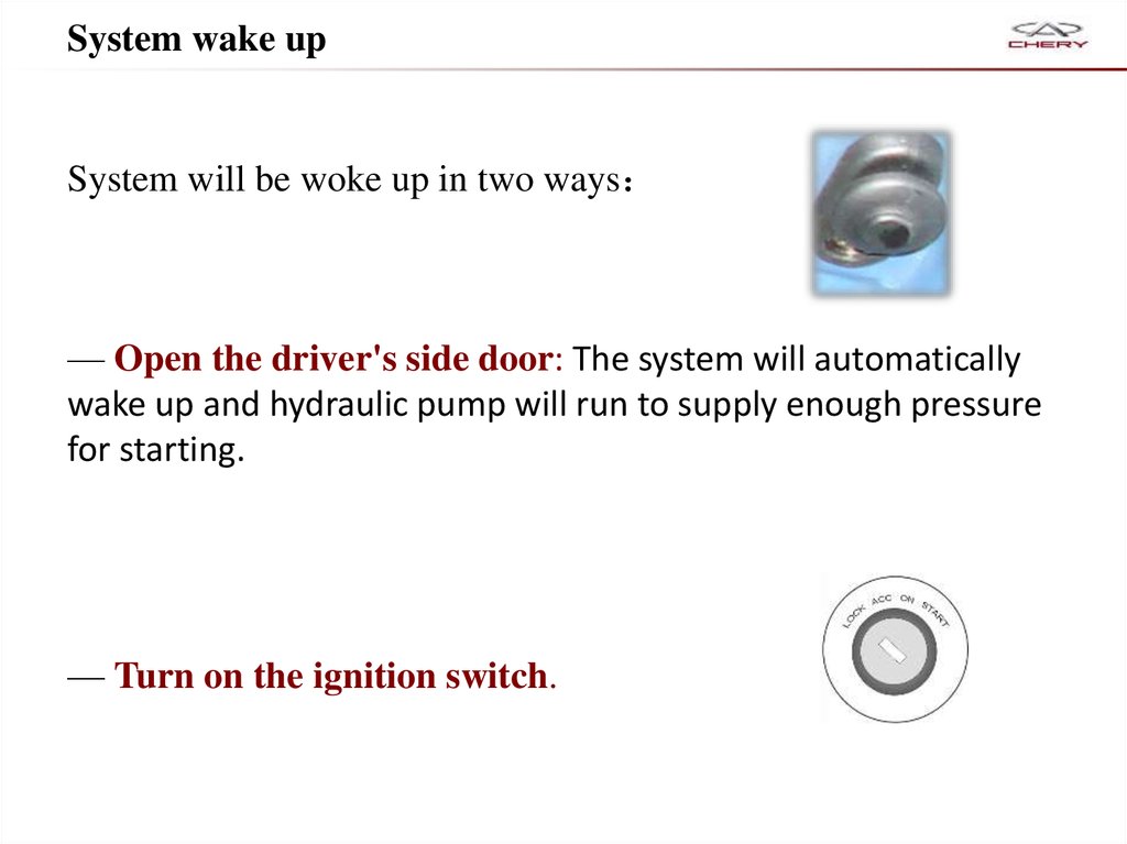
System wake upSystem will be woke up in two ways
— Open the driver's side door: The system will automatically
wake up and hydraulic pump will run to supply enough pressure
for starting.
— Turn on the ignition switch.
20.
Engine start controlStart requirement
1.
2.
Once TCU receives the brake (except Neutral gear) and the start signal, it
will automatically ground the control wire and run the starter.
After starting conditions are met, TCU simultaneously through CAN bus
to send a start signal to allow engine control system (ECU) to start.
Emergency start:
Battery with low energy fails to start engines but with enough electric power
to run the pump supplying enough fluid pressure to shift operations, that is
gears can still be engaged.
Set the transmission under Manual mode and pull vehicle to certain low
speed, shift the gear manually to 1st/2nd gear.
21.
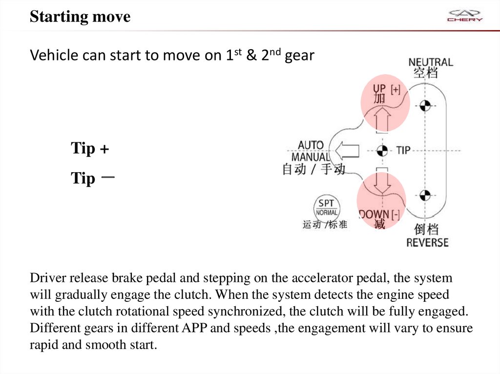
Starting moveVehicle can start to move on 1st & 2nd gear
Tip +
Tip
Driver release brake pedal and stepping on the accelerator pedal, the system
will gradually engage the clutch. When the system detects the engine speed
with the clutch rotational speed synchronized, the clutch will be fully engaged.
Different gears in different APP and speeds ,the engagement will vary to ensure
rapid and smooth start.
22.
Shift process under Manual ModeShift process
When vehicle is running and the clutch engaged, driver can manually shift gears.
Three stages:
Stage 1: engine decrease torque output
Stage 2: shift process
Stage 3: increase engine torque output
Shift request will only be accepted by ECU when it does not cause the overspeed or
stall.
23.
Control intervention under Manual ModeIn Manual mode, TCU will control the gears automatically avoid overspeed or stall
under following situations:
1.Downshift intervention: higher gear when the driver began to slow down, the
system will automatically help the driver to downshift.
2.Upshift intervention: System will automatically upshift avoid overspeed.
Attention: that these two cases the system is still in manual mode, the
following, the main reason is to help the driver to take control rather than
driving engine for the purpose of protection, engine protection should be the
engine control system (EMS) functions.
24.
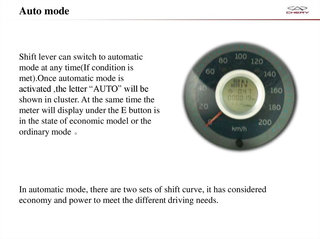
Auto modeShift lever can switch to automatic
mode at any time(If condition is
met).Once automatic mode is
activated ,the letter “AUTO” will be
shown in cluster. At the same time the
meter will display under the E button is
in the state of economic model or the
ordinary mode 。
In automatic mode, there are two sets of shift curve, it has considered
economy and power to meet the different driving needs.
25.
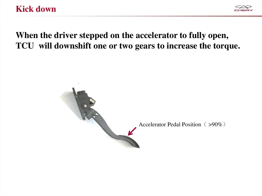
Kick downWhen the driver stepped on the accelerator to fully open,
TCU will downshift one or two gears to increase the torque.
Accelerator Pedal Position >90%
26.
DecelerationTCU will automatically downshift during deceleration and the
gears above 2nd gear.
For example, in 5th gear, clutch engaged and accelerator pedal released, when
the engine speed reach idle speed, the system will automatically downshift
from 5th to 4th , to avoid the engine speed drops below the target idle speed
which led to stall.
When a downshift depends on the following parameters: stalls, engine idling,
the brake pedal and engine deceleration rate.
Continuous deceleration until the vehicle stopped, TCU will be automatically
shift to Neutral, and disengage the clutch.
Auto clutch engagement
During the downhill and the vehicle speed increase, if the gear engaged during
running and APP was released, when the reach a certain speed, the clutch will
automatically engage to provide engine braking.
27.
System security features28.
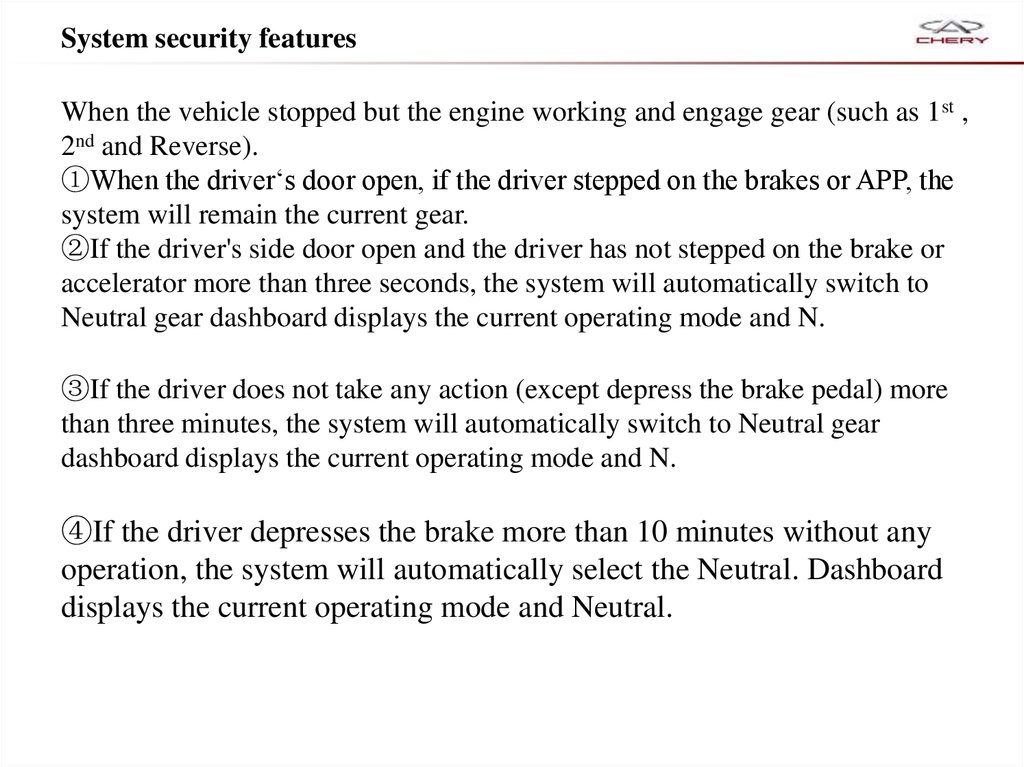
System security featuresWhen the vehicle stopped but the engine working and engage gear (such as 1st ,
2nd and Reverse).
①When the driver‘s door open, if the driver stepped on the brakes or APP, the
system will remain the current gear.
②If the driver's side door open and the driver has not stepped on the brake or
accelerator more than three seconds, the system will automatically switch to
Neutral gear dashboard displays the current operating mode and N.
③If the driver does not take any action (except depress the brake pedal) more
than three minutes, the system will automatically switch to Neutral gear
dashboard displays the current operating mode and N.
④If the driver depresses the brake more than 10 minutes without any
operation, the system will automatically select the Neutral. Dashboard
displays the current operating mode and Neutral.
29.
System security featuresEmergency start during brake switch is broken
If the TCU detected brake switch is broken, Ignition key
remains in the starting position about 10 seconds before
starting vehicle. After the start, TCU will inform the
driver by warning lights.
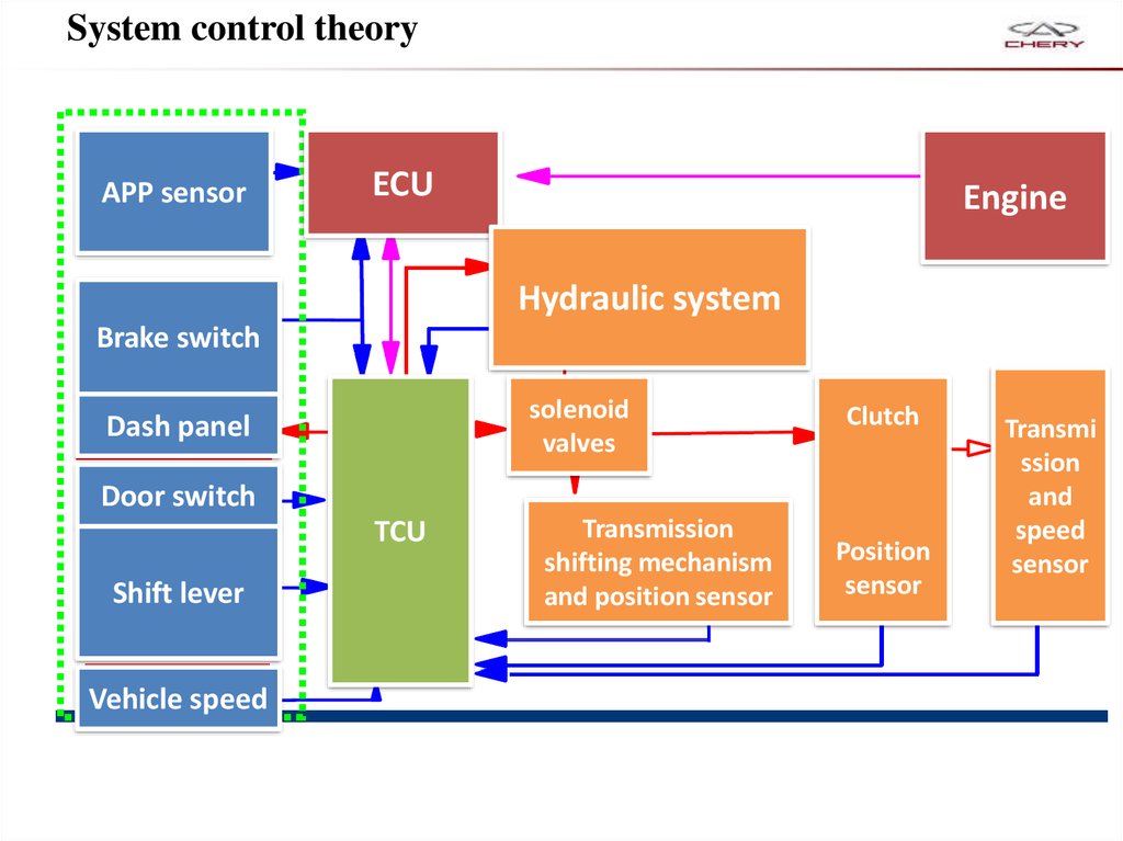
30.
System control theoryAPP sensor
ECU
Engine
Hydraulic system
Brake switch
solenoid
valves
Dash panel
Clutch
Door switch
TCU
Shift lever
Vehicle speed
Transmission
shifting mechanism
and position sensor
Position
sensor
Transmi
ssion
and
speed
sensor
31.
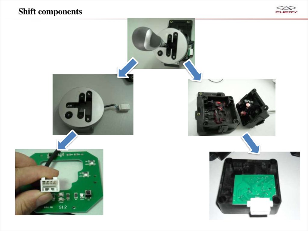
Components32.
Shift components33.
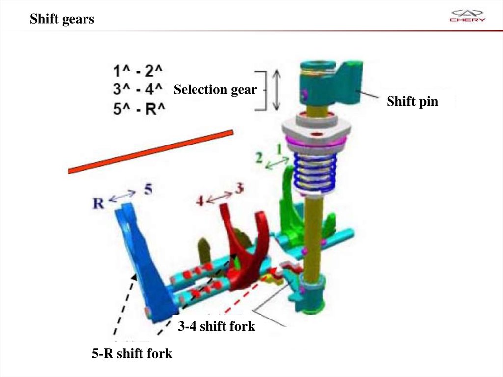
Shift gearsSelection gear
3-4 shift fork
5-R shift fork
Shift pin
34. Hydraulic actuator
SQR 513 transmission hydraulic actuator locationBracket of hydraulic actuator must be remove
35. Power Unit
Hydraulic power unit provides power to hydraulic.Accumulator
Low pressure fluid
hose
Fluid tank
High pressure pipe
Motor
Gear pump
36. Pump
3012V DC。
System pressure:
<36 bar run
>46 bar stop
TCU
Electric
connector
Gear
pump
motor
31
37. Tank
150 micrometer filter was fitted in exports of tank.Fluid level standard
Relief system pressure using X431 and
then observe the liquid level inside the
tank.
Pressure fluid manufacturer: -TUTELA CAR CS SPEED
PN:EW.0011602.A
38. Accumulator
Capacity:250 cm339. Valve body
Valve body has follow functions1. Control gear engage and detach。
2. Control gear selection
3. Control clutch engage and detach
Components:
1. Clutch solenoid valve(EV0)
2. Even gear engage valve(EV2)
3. Odd gear engage valve(EV1)
4. 1-2 selection gears solenoid valve(EV3)
5. 5-R selection gears solenoid valve(EV4)
6. Gear engage position sensor
7. Gear selection position sensor
8. Press sensor 0-70 bar
9. Valve body
40. Valve body
Mountinglocation
Joint
41. Clutch actuator
42. Clutch actuator assembly
1. Release cable2. Clutch actuator body
3. Clutch cable position sensor
4. System air bleed bolt
Clutch
solenoid
valve (EV0)
1
4
2
3
43.
Data stream in X431 concerning clutch44. Clutch cable position sensor
Function: feedback the clutch cable position signal to TCUDATA stream
IG ON, Engine off,
1st gear
IG ON, Engine off,
Neutral gear
Engine running
Neutral gear
Clutch actuator position
26.356mm
26.312
18.084mm
Clutch actuator position
Reference
26.356mm
26.268
18.084mm
45.
Gear engage and selection solenoid valves46. Gear engage solenoid valves
Even gearengage
valve(EV2)
Odd gear
engage
valve(EV1)
47. Gear selection valves
1-2 gears selectionsolenoid valve(EV3)
5-R gears selection
solenoid valve(EV4)
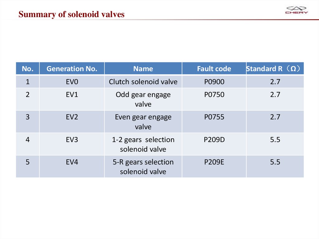
48.
Summary of solenoid valvesNo.
Generation No.
Name
Fault code
Standard R Ω
1
EV0
Clutch solenoid valve
P0900
2.7
2
EV1
Odd gear engage
valve
P0750
2.7
3
EV2
Even gear engage
valve
P0755
2.7
4
EV3
1-2 gears selection
solenoid valve
P209D
5.5
5
EV4
5-R gears selection
solenoid valve
P209E
5.5
49. Pressure sensor
Function :Monitor system pressure50. Pressure sensor
Pressure output voltage characteristicsTCU
+
Voltage(V)
Pressure (bar)
What is special meaning that the range from 36-46 bar?
-
51.
Maintenance specification——AMT system self-learn
52. System maintenance services
Replace or assemble parts must perform the following functions in wholeor in part:
NO.
service1
System air-bleed
service2
Relief system pressure
service3
Clutch kiss point self-learn
service4
Gear self- learn
service6
New actuator
×
Shift lever self-learn
service5
Clear the data in the TCU
×
Write data
After replace the following parts: clutch actuator, tank, pump, high pressure pipe, pressure
sensors, accumulators and other major parts, Bleed the system 3, and then take gear self-learn
one time, 3 to 5 times the clutch self-learning. Finally check the oil level according to the method.
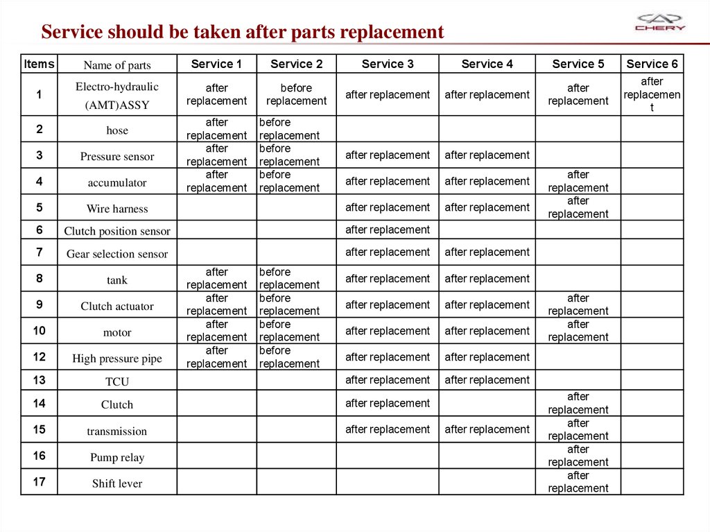
53.
Service should be taken after parts replacementItems
1
Name of parts
Service 1
Service 2
Electro-hydraulic
after
replacement
before
replacement
(AMT)ASSY
after
replacement
after
replacement
after
replacement
before
replacement
before
replacement
before
replacement
Service 3
Service 4
Service 5
Service 6
after replacement
after replacement
after
replacement
after
replacemen
t
after replacement
after replacement
after replacement
after replacement
after replacement
2
hose
3
Pressure sensor
4
accumulator
5
Wire harness
after replacement
6
Clutch position sensor
after replacement
7
Gear selection sensor
after replacement
after replacement
8
tank
after replacement
after replacement
9
Clutch actuator
after replacement
after replacement
10
motor
after replacement
after replacement
12
High pressure pipe
after replacement
after replacement
13
TCU
after replacement
after replacement
14
Clutch
after replacement
15
transmission
after replacement
16
Pump relay
17
Shift lever
after
replacement
after
replacement
after
replacement
after
replacement
before
replacement
before
replacement
before
replacement
before
replacement
after replacement
after
replacement
after
replacement
after
replacement
after
replacement
after
replacement
after
replacement
after
replacement
after
replacement
54.
Maintenance specification——Guide of dismount and assemble
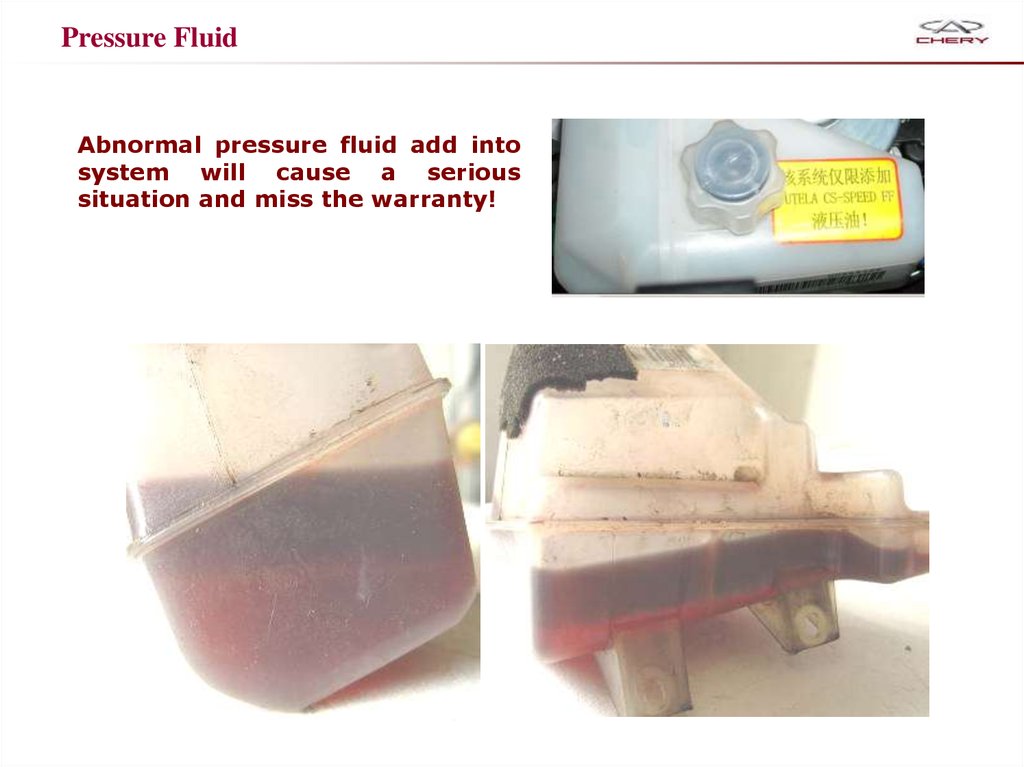
55.
Pressure FluidAbnormal pressure fluid add into
system will cause a serious
situation and miss the warranty!
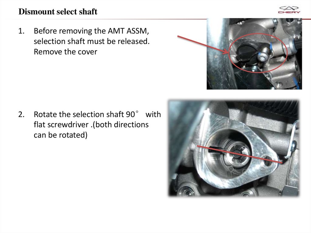
56.
Dismount select shaft1.
Before removing the AMT ASSM,
selection shaft must be released.
Remove the cover
2.
Rotate the selection shaft 90° with
flat screwdriver .(both directions
can be rotated)
57.
Mount guide1. First of all, after cleaning and coating sealant,
should ensure a good seal interfaces
2.
Adjust the transmission gear selector position to
Neutral
2.
Fasten the bolts
3.
Assemble the release cable
58.
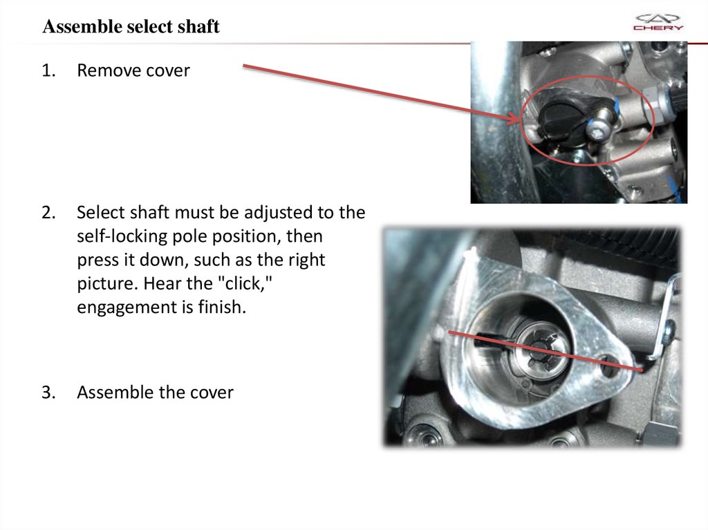
Assemble select shaft1.
Remove cover
2.
Select shaft must be adjusted to the
self-locking pole position, then
press it down, such as the right
picture. Hear the "click,"
engagement is finish.
3.
Assemble the cover
59.
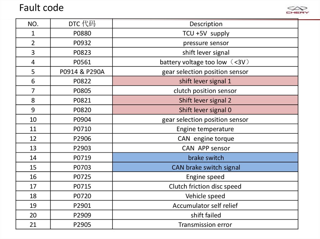
Fault codeNO.
1
2
3
4
5
6
7
8
9
10
11
12
13
14
15
16
17
18
19
20
21
DTC 代码
P0880
P0932
P0823
P0561
P0914 & P290A
P0822
P0805
P0821
P0820
P0904
P0710
P2906
P2903
P0719
P0703
P0725
P0715
P0720
P2901
P2909
P2905
Description
TCU +5V supply
pressure sensor
shift lever signal
battery voltage too low <3V
gear selection position sensor
shift lever signal 1
clutch position sensor
Shift lever signal 2
Shift lever signal 0
gear selection position sensor
Engine temperature
CAN engine torque
CAN APP sensor
brake switch
CAN brake switch signal
Engine speed
Clutch friction disc speed
Vehicle speed
Accumulator self relief
shift failed
Transmission error
60.
Fault code22
23
24
25
26
27
28
29
30
31
32
33
34
35
36
37
38
39
40
41
42
43
44
P2904
P2908
P2900
P0825
P0933
P0755
P0750
P0900
P290E
P290D
P0701
P0881
P081A
P0945
P0560
P0780
P2712
P0942
P0613
P060C
U1701
U1601
P0604
clutch error
clutch control error
ECO button
shift lever stuck
Pump relay error
even gears shift solenoid valve
Odd gears shift solenoid valve
Clutch solenoid valve
5 R gears selection solenoid valve
1 2 gears selection solenoid valve
solenoid valve interior fault
TCU 12V power supply
starter relay
pump relay open or ground
battery voltage too low
Illogical operation
pressure system relief and leakage
system pressure too or pump overheat
SMP (vice-processor error
MMP main processor error
CAN bus fault
CAN fault
microprocessor error
61.
Trouble-shooting andsolutions
62.
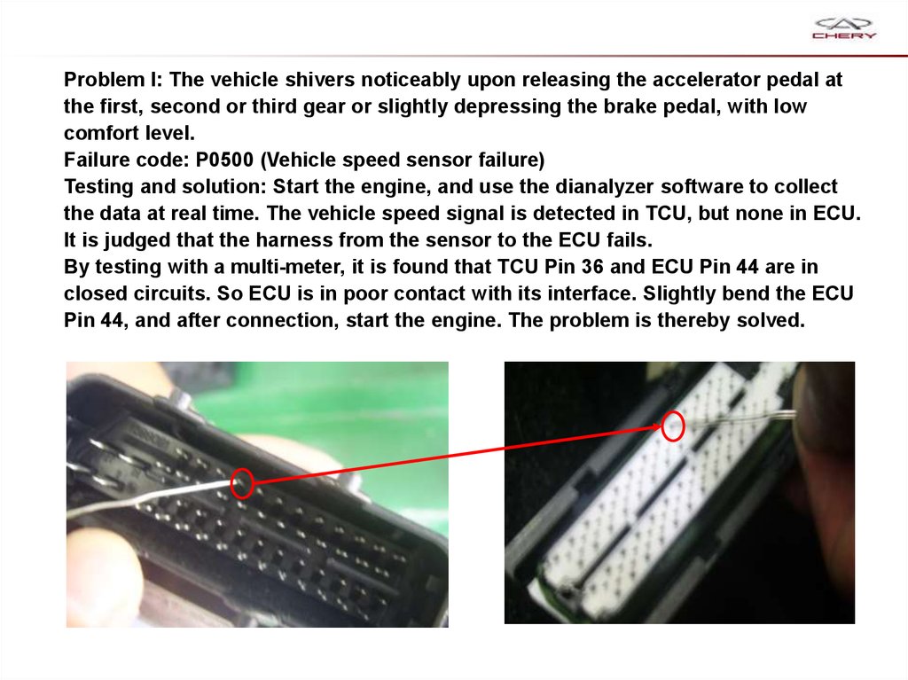
Problem I: The vehicle shivers noticeably upon releasing the accelerator pedal atthe first, second or third gear or slightly depressing the brake pedal, with low
comfort level.
Failure code: P0500 (Vehicle speed sensor failure)
Testing and solution: Start the engine, and use the dianalyzer software to collect
the data at real time. The vehicle speed signal is detected in TCU, but none in ECU.
It is judged that the harness from the sensor to the ECU fails.
By testing with a multi-meter, it is found that TCU Pin 36 and ECU Pin 44 are in
closed circuits. So ECU is in poor contact with its interface. Slightly bend the ECU
Pin 44, and after connection, start the engine. The problem is thereby solved.
63.
Problem II: The transmission failure lamp is lit during movement, and the failurecode P0715 (friction disc revolution sensor open circuit) is indicated, with the
gearshift disabled.
Testing and solution: Revolution signal failure; TCU issues the gear locking
command. Remove the revolution sensor, and add a 0.2mm shim. Thereafter,
upgrade TCU data to its latest version CAA05QN0 , and carry out the gear selflearn and clutch engagement point self-learn.
Add a 0.2mm
shim here.
64.
Problem III: Friction disc revolution sensor failure; the gear is locked at thefirst/second gear, allowing no shift to higher gears. After the failure code is
eliminated and the self-learn conducted, this problem appears again later.
Causes:
1.Disproportionate speed ratio: Under certain operating conditions (for example,
from first gear to the reverse gear, or from the reverse gear to the neutral gear), the
radial run-out may occur on the shaft on which the signal wheel is mounted in the
transmission, leading to the abnormality of signals collected by the clutch speed
sensor. This case may bring an incorrect proportion among the engine revolution,
clutch revolution and vehicle speed, consequently resulting in the wrong report by
TCU and the activation of the safe operation mode.
2. No signals from the clutch revolution sensor: Under certain operating conditions
(for example, from first gear to the reverse gear, or from the reverse gear to the
neutral gear), the severe radial run-out may occur on the shaft on which the signal
wheel is mounted in the transmission, leading to the mutual interference between
the signal wheel and the senor and also the damages of the senor, which further
causes no signal output, to consequently result in the wrong report by TCU and the
activation of the safe operation mode.
3. Serious skidding of the clutch: Owing to the serious wear of the clutch, there is a
significant deviation in the proportion among the engine revolution, clutch
revolution and vehicle speed under certain working conditions.
65.
4. Clutch position sensor failure (in this case, P1810 and P0715 will be indicated atthe same time): Some vehicles are not made accessible to such a technical
upgrade that a waterproof pad is provided for the clutch position sensor, which
leads to the water ingress into the sensor, consequently resulting in this problem.
5. transmission internal failure, for example, the disabled gear locking function (in
this case, P1818 or P0720 will be indicated at the same time): The speed ratio
does not conform to the actual gear.
6. Other electric failures (may be accompanied by the failure code 1810): The
harness is damaged or improperly earthed.
Solutions:
1. Renew TCU, and calibrate it to CAA04OH0 version: This problem corresponds to
Problem I (the disproportionate speed ratio), and the solution is to largely
increase the judgment threshold value.
2. Repair of transmission: If there is interference between the transmission signal
wheel and the senor, and the sensor is damaged, the recovery by software is
impossible, but the only way is to repair the transmission.
3. Water ingress in the clutch position sensor: Replace this sensor and provide
waterproof pad (this pad will be supplied together with the sensor).
4. Clutch skidding: Replace the clutch, and use a diagnoser to initiate the TCU.
66.
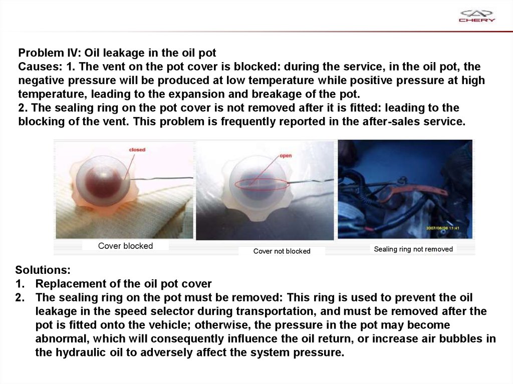
Problem IV: Oil leakage in the oil potCauses: 1. The vent on the pot cover is blocked: during the service, in the oil pot, the
negative pressure will be produced at low temperature while positive pressure at high
temperature, leading to the expansion and breakage of the pot.
2. The sealing ring on the pot cover is not removed after it is fitted: leading to the
blocking of the vent. This problem is frequently reported in the after-sales service.
Cover blocked
Cover not blocked
Sealing ring not removed
Solutions:
1. Replacement of the oil pot cover
2. The sealing ring on the pot must be removed: This ring is used to prevent the oil
leakage in the speed selector during transportation, and must be removed after the
pot is fitted onto the vehicle; otherwise, the pressure in the pot may become
abnormal, which will consequently influence the oil return, or increase air bubbles in
the hydraulic oil to adversely affect the system pressure.
67.
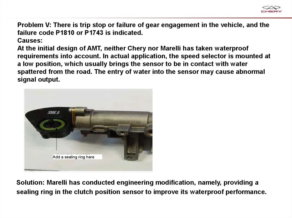
Problem V: There is trip stop or failure of gear engagement in the vehicle, and thefailure code P1810 or P1743 is indicated.
Causes:
At the initial design of AMT, neither Chery nor Marelli has taken waterproof
requirements into account. In actual application, the speed selector is mounted at
a low position, which usually brings the sensor to be in contact with water
spattered from the road. The entry of water into the sensor may cause abnormal
signal output.
Add a sealing ring here
Solution: Marelli has conducted engineering modification, namely, providing a
sealing ring in the clutch position sensor to improve its waterproof performance.
68.
Problem VI: One of direct gears is always missing in the operation, for example, thetransmission directly moves from the second gear to the fourth gear, with the third
gear skipped, but can directly move from the fourth gear to the third gear.
Sometimes, a failure code P1810 will be indicated; when the vehicle is stopped, all
gears will work correctly.
Causes:
1. The synchronizer of the transmission is excessively worn, and can’t work. If
serious , the sound of collision of teeth may be heard. This case mostly occurs
in vehicles produced prior to 2007.
2. The transmission synchronizer is separated.
3. One of direct gears is always missing during the operation.
Solution:
1. In the first case, relevant parts must be replaced.
2. In the second case, only the reassembly of the transmission is required.
69.
Problem VII1. No depression of the accelerator pedal is required in the engagement of the first gear when the
vehicle moves.
2. The vehicle shivers seriously at the beginning of movement, but restores its normal operation
after the move-up.
Causes:
1. The clutch engagement point self-learn is not conducted, or the system is not disconnected
from the power supply after the self-learn is finished. (Note: The data can be only successfully
written into TCU 10s after the ignition switch is turned off after the each self-learn is finished.)
2. The clutch is not replaced until it skids due to the excessive wear. After the replacement, TCU
is not initialized via a diagnoser.
3. The clutch friction plate is uneven, including new parts. (This case may occur at self-learn of
the engagement point. The return values after each learn are different, which can be used for
judgment.)
4. There is water ingress in the clutch position sensor.
5. The clutch and TCU calibrations are misused.
Solutions:
1. Relevant personnel in the service station shall learn how to use the diagnoser. Each time after
any part is replaced, the self-learn (clutch engagement point self-learn, gear self-learn) shall be
conducted. The power supply shall be disconnected for 10s after the self-learn.
2. Replace the Valeo clutch and upgrade the TCU calibration to CAA05QM5: CAA04QHO is used
together with Changchun Yidong clutch, while CAA05QM5 is used together with Valeo clutch.
No confusion is allowed; otherwise, the vehicle may move up automatically, or does not move
after refueling, or gears can’t be shifted smoothly.
70.
Problem VIII:After the transmission is shifted to the first gear and the vehicle is stopped,
the neutral gear is engaged automatically and immediately.
Possible causes:
1. The cab door lamp switch is disabled. (Move the roof lamp switch to its
middle position, and if the lamp is lit suddenly, this fault can be identified.)
Solutions:
1. Replace the door switch.
71.
72. Pratice
Check resistence of each solenoid valve。
Function
Resistence
EV0
EV1
EV2
EV3
EV4
Remove gear selection/gear engage sensor/ clutch sensor and how it works
Perform how to check the oil level.
Gear and clutch self-learn
73. Pratice
Function the location of following parts
location
Pressure Pump relay
TCU
ECU
Disconnect the following part,find how the vehicle works and use X431
to detect the falut code
Vehicle can run?/fault light on?
Pressure Pump relay
Engine speed sensor
Clutch speed sensor
Vehicle speed sensor
Fault code