


 mechanics
Similar presentations:


Internal Сombustion Engine. Fuel Systems. The carburetors
1. Internal Сombustion Engine
Fuel SystemsThe carburetors
Aleksey Terentyev
2. Aleksey Terentyev
Contact Information:Izhevsk State Technical University,
7 Studencheskaya street, Building 2, Room 415
426069, Izhevsk, Russia
Office phone:
7 (3412) 77-31-59
Internal office phone:
23-02
Mobile phone
8-912-752-29-47
E-mail:
tdu_teran@mail.ru
Personal data:
Education
Izhevsk State Technical University (OF ISTU) 10.1993 – 02.1999
Specialty: Engineer-mechanic-Engine Construction and Test
Post graduate course at the Izhevsk State Technical University (of ISTU)
03.1999 – 05.2005
Outcome: PhD degree in Technique – «Noise and Vibration of the Car»
Position
An associate professor at the Izhevsk State Technical University named
after Mikhail Kalashnikov
Date of Birth: 30.11.1975
Work experience: from 1999
2
3. The carburetor
The carburetor is a device used to mix proper amounts of airand fuel together in such a way that the greatest amount of heat energy
is obtained when the mixture is compressed and ignited in the
combustion chamber of the engine.
The function of the carburetor is to mix the correct amount of
fuel with sufficient air so the fuel atomizes (breaks up), allowing it to
become a highly volatile vapor.
3
4.
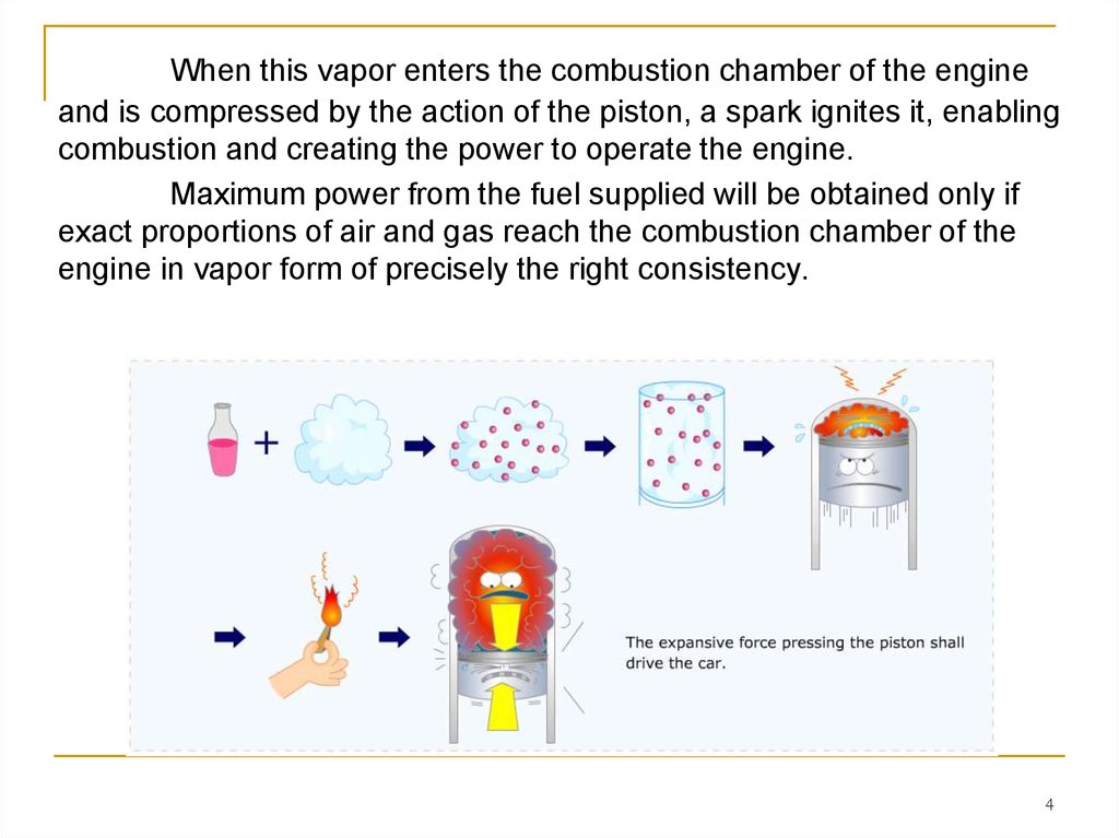
When this vapor enters the combustion chamber of the engineand is compressed by the action of the piston, a spark ignites it, enabling
combustion and creating the power to operate the engine.
Maximum power from the fuel supplied will be obtained only if
exact proportions of air and gas reach the combustion chamber of the
engine in vapor form of precisely the right consistency.
4
5.
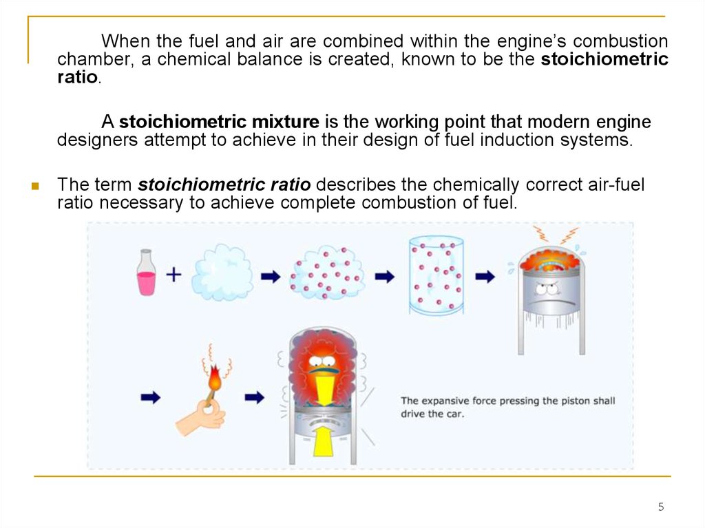
When the fuel and air are combined within the engine’s combustionchamber, a chemical balance is created, known to be the stoichiometric
ratio.
A stoichiometric mixture is the working point that modern engine
designers attempt to achieve in their design of fuel induction systems.
The term stoichiometric ratio describes the chemically correct air-fuel
ratio necessary to achieve complete combustion of fuel.
5
6.
The ratio of air to fuel in a theoretically perfect stoichiometric mixture isapproximately 15:1; that is, the mass of air is 15 times the mass of the
fuel. This means that, in a perfect situation, there would be 15 parts of air
for each part of fuel.
Any mixture in which the ratio is less than 15:1 is considered to be a rich
mixture;
any mixture in which the ratio is more than 15:1 is considered to be a
lean mixture.
It’s important to note that this ratio is measured by mass and not by
volume.
6
7.
Table lists the proper amounts of air and fuel, with regard todifferent engine running conditions
Table 1 Air–fuel mixtures at different engine running conditions
7
8.
Gasoline is a liquid. Oxygen, on the other hand, is a gas andhas the ability to burn.
The most efficient combustion of gasoline and oxygen occurs
only when they’re combined and turned into a vapor from the heat
produced by the engine.
This is a delicately balanced mixing process accomplished by
the carburetor. Two primary principles are involved in carburetion
operation:
■ The principle of atomization
■ The Venturi principle
Let’s look at each of these principles in detail.
8
9. Principle of Atomization
Atomization is the process of combining air and liquid, in this casefuel, to create a mixture of liquid droplets suspended in air.
As the piston begins the intake stroke, the air pressure in the
cylinder is reduced. The pressure difference causes the higher-pressure,
outside air to flow through the air filter and carburetor, and into the
engine.
Atomization takes
place when the carburetor
meters gasoline into the
fastmoving air passing
through it using the same
principle of pressure
difference (Figure 1).
9
10.
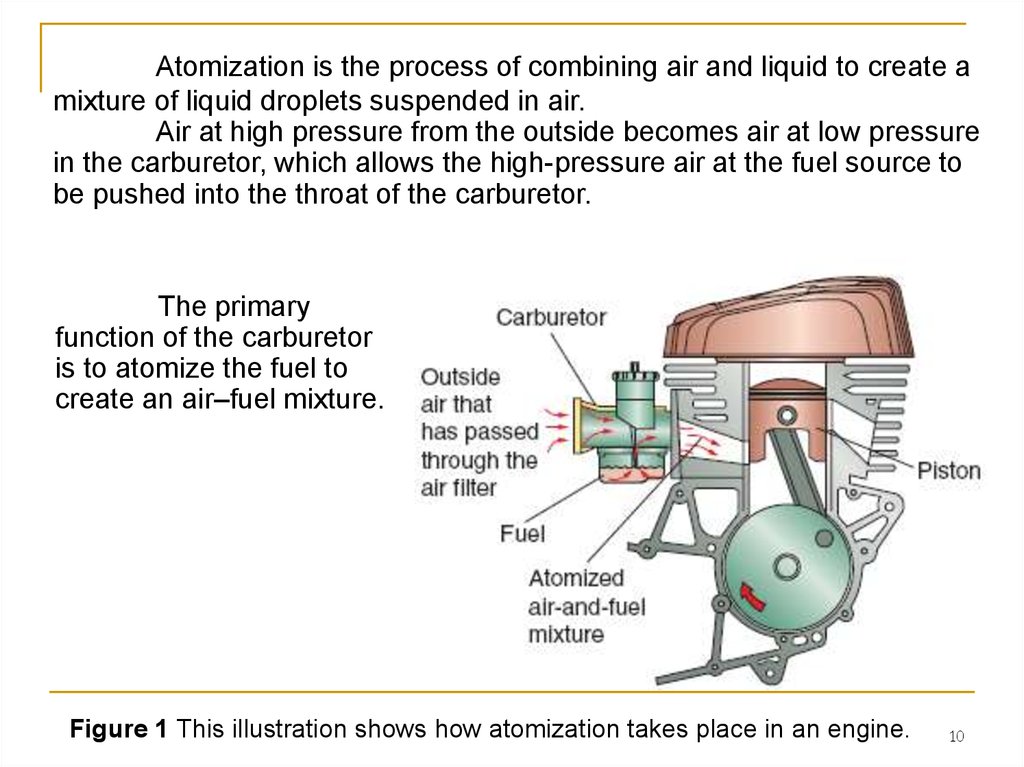
Atomization is the process of combining air and liquid to create amixture of liquid droplets suspended in air.
Air at high pressure from the outside becomes air at low pressure
in the carburetor, which allows the high-pressure air at the fuel source to
be pushed into the throat of the carburetor.
The primary
function of the carburetor
is to atomize the fuel to
create an air–fuel mixture.
Figure 1 This illustration shows how atomization takes place in an engine.
10
11. The Venturi Principle
Carburetor design is based on the Venturi principle.The Venturi principle simply states that a gas or liquid that’s
flowing through a narrowed-down section (venturi) of a passage will
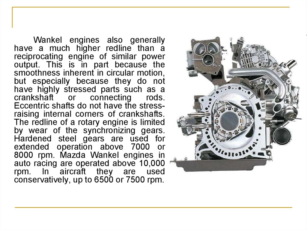
increase in speed and decrease in pressure compared with the speed
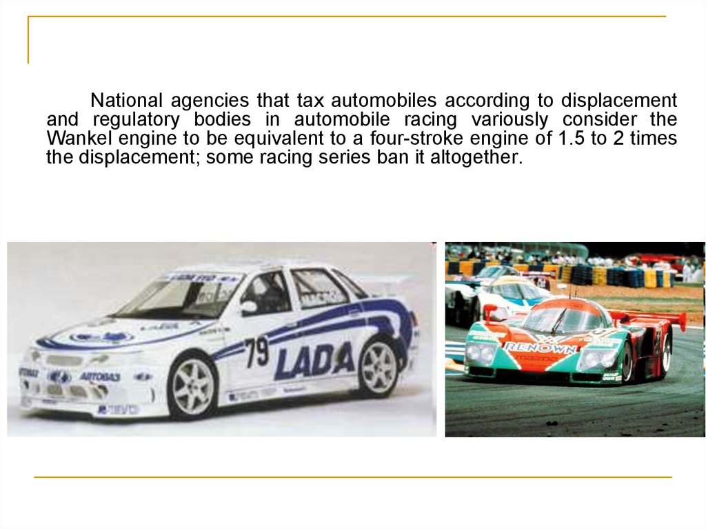
and pressure in wider sections of the passageway (Figure 2).
11
12.
A venturi has a particular shape—a modified hourglass figure,you might say. Air from the carburetor, on its way to the combustion
chamber, passes through the venturi.
The hourglass shape of the venturi causes the stream of air to
increase in speed and decrease in pressure, creating a pressure
difference in the venturi.
This pressure difference is important, as it allows for fuel to be
drawn into the air stream and atomized.
Figure 2 The Venturi principle.
12
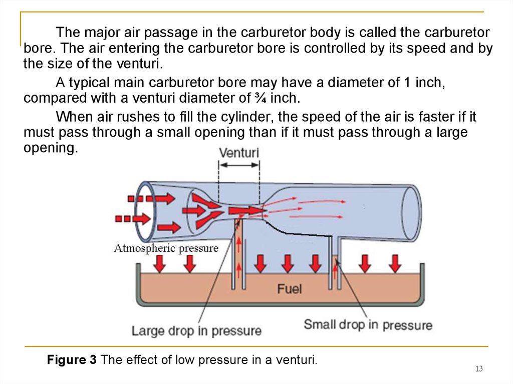
13.
The major air passage in the carburetor body is called the carburetorbore. The air entering the carburetor bore is controlled by its speed and by
the size of the venturi.
A typical main carburetor bore may have a diameter of 1 inch,
compared with a venturi diameter of ¾ inch.
When air rushes to fill the cylinder, the speed of the air is faster if it
must pass through a small opening than if it must pass through a large
opening.
Figure 3 The effect of low pressure in a venturi.
13
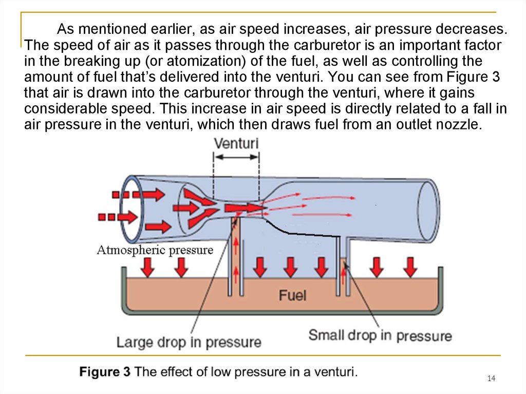
14.
As mentioned earlier, as air speed increases, air pressure decreases.The speed of air as it passes through the carburetor is an important factor
in the breaking up (or atomization) of the fuel, as well as controlling the
amount of fuel that’s delivered into the venturi. You can see from Figure 3
that air is drawn into the carburetor through the venturi, where it gains
considerable speed. This increase in air speed is directly related to a fall in
air pressure in the venturi, which then draws fuel from an outlet nozzle.
14
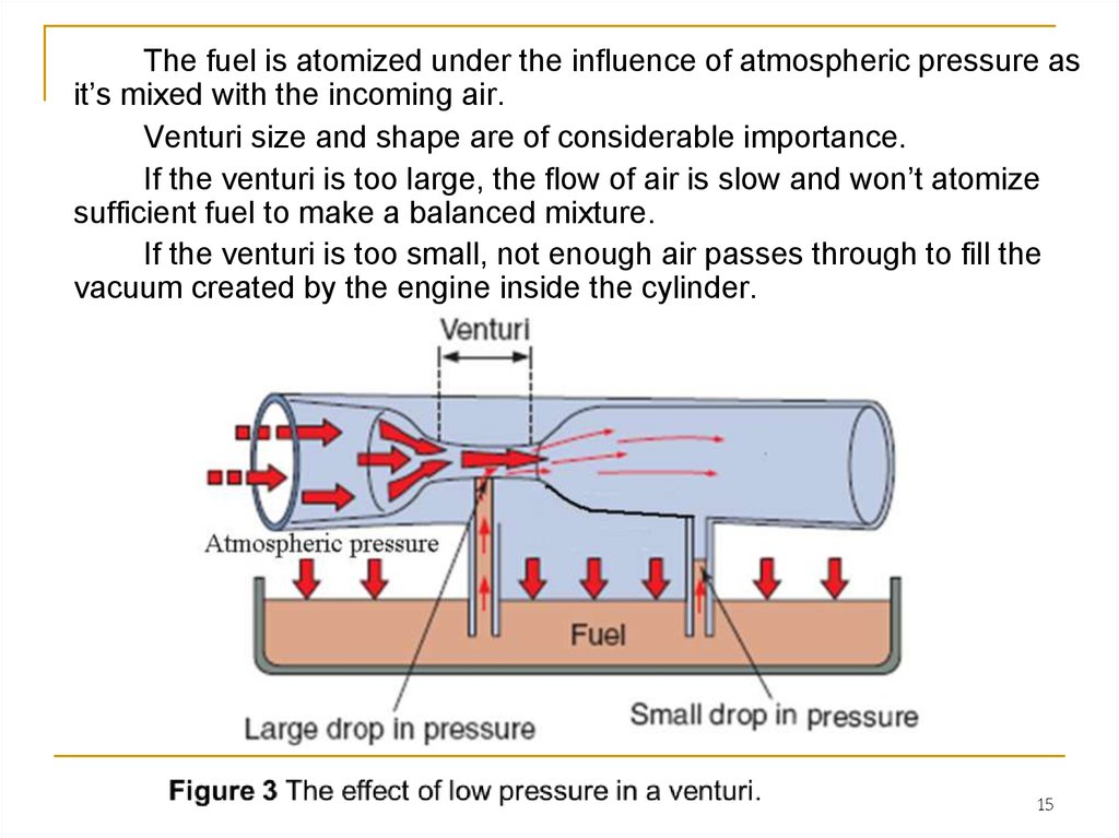
15.
The fuel is atomized under the influence of atmospheric pressure asit’s mixed with the incoming air.
Venturi size and shape are of considerable importance.
If the venturi is too large, the flow of air is slow and won’t atomize
sufficient fuel to make a balanced mixture.
If the venturi is too small, not enough air passes through to fill the
vacuum created by the engine inside the cylinder.
15
16.
A large engine that creates a high vacuum uses a carburetor with alarge venturi. A small engine requires a smaller venturi to be most
effective.
Carburetors are equipped with mechanisms for regulation of the air
and fuel volumes that are allowed to pass through the venturi. All
carburetors have a venturi that operates on the same basic principle.
Variations are in size, method of attachment, or in the system used to
open and close the venturi. The principle of operation is the same for all
carburetors.
16
17. FUEL DELIVERY SYSTEMS
The various components of the fuel delivery system of mostgasoline-powered engines will be discussed in this section.
Fuel Tank
The fuel tank is designed to store fuel (gasoline). Fuel tanks can be
made of steel, aluminum, or plastic. Fuel tanks of almost all modern
power equipment engines are made of a light, thin steel or plastic.
The important thing to remember is that the fuel tank is a reservoir
that safely stores a supply of fuel for the carburetion system (Figure 4).
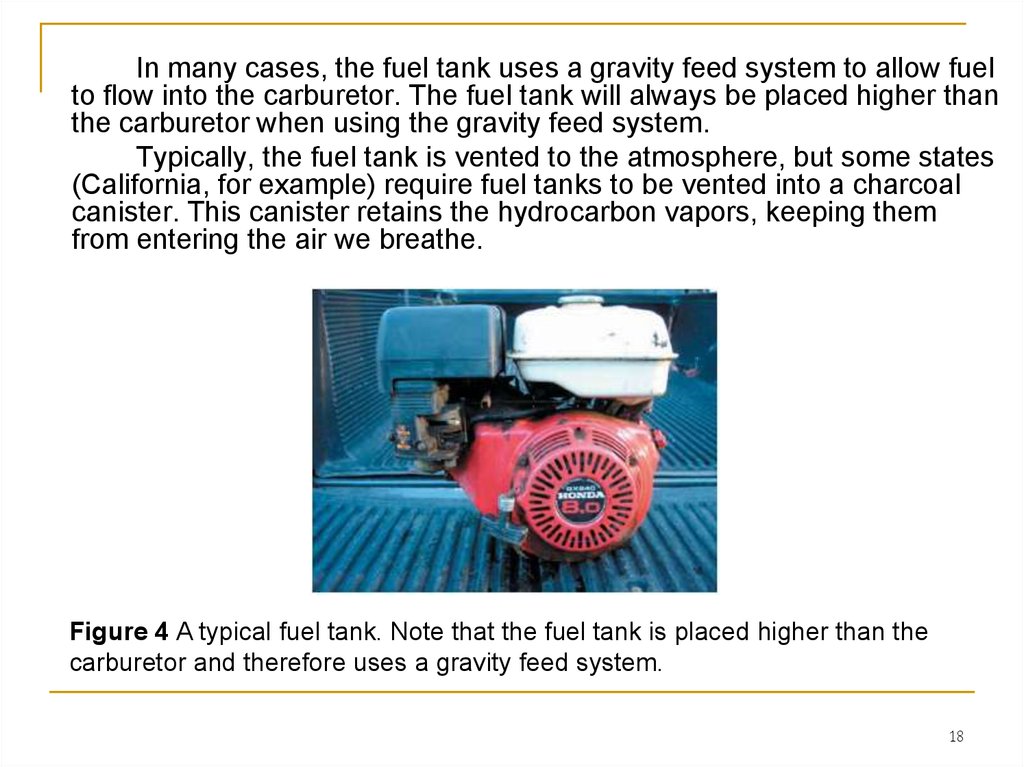
Figure 4 A typical fuel tank. Note that the fuel tank is placed higher than the
carburetor and therefore uses a gravity feed system.
17
18.
In many cases, the fuel tank uses a gravity feed system to allow fuelto flow into the carburetor. The fuel tank will always be placed higher than
the carburetor when using the gravity feed system.
Typically, the fuel tank is vented to the atmosphere, but some states
(California, for example) require fuel tanks to be vented into a charcoal
canister. This canister retains the hydrocarbon vapors, keeping them
from entering the air we breathe.
Figure 4 A typical fuel tank. Note that the fuel tank is placed higher than the
carburetor and therefore uses a gravity feed system.
18
19. Fuel Valves
Fuel valves, also known as fuel petcocks, are on/off valves thatcontrol the flow of gasoline from the fuel tank to the carburetion system
(Figure 5). Fuel valves are generally operated manually by turning the
valve either on or off.
Figure 5 Fuel valves are designed to open and close the flow of fuel to the
carburetor.
19
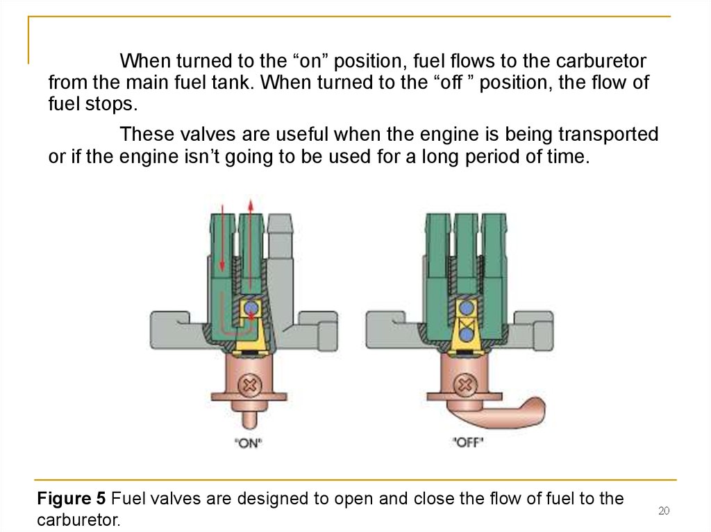
20.
When turned to the “on” position, fuel flows to the carburetorfrom the main fuel tank. When turned to the “off ” position, the flow of
fuel stops.
These valves are useful when the engine is being transported
or if the engine isn’t going to be used for a long period of time.
Figure 5 Fuel valves are designed to open and close the flow of fuel to the
carburetor.
20
21. Fuel Lines
Fuel lines are used to flow gasoline from the fuel valve to thecarburetion system and are usually made of metal or neoprene, which is a
synthetic rubber material.
It’s important to use manufacturer-recommended fuel lines. Because
of some additives and alcohol (in certain cases where it’s used as an
additive) in gasoline manufactured nowadays, inferior fuel line hose can
be affected or damaged.
21
22. Fuel Pumps
Some power equipment engines use a fuel pump. The purposeof a fuel pump is to deliver fuel from the fuel tank to the carburetion
system. A fuel pump is also required when the power equipment
engine’s fuel tank is placed lower than the carburetor. The fuel pump
supplies fuel under pressure to keep the carburetor filled with fuel.
Fuel pumps are found always in engines with fuel injection
systems. Fuel injection is a type of carburetion and is discussed
later.
There are three types of fuel pumps:
- mechanical,
- vacuum,
- electric.
Although some larger power equipment diesel engines use
mechanical fuel pumps, two types of pumps are commonly seen on
modern power equipment engines: vacuum and electric.
22
23. Mechanical Fuel Pumps
The mechanical fuel pump is a pump that uses a diaphragm operatedby a rocker arm.
The rocker arm is opened by the camshaft and closed by a spring to
pump fuel from the tank to the carburetor (Figure 6).
Mechanical pumps are generally located on the side of the engine
block. The rocker arm enters the engine and rides on a camshaft lobe.
Figure 6 A mechanical fuel pump.
23
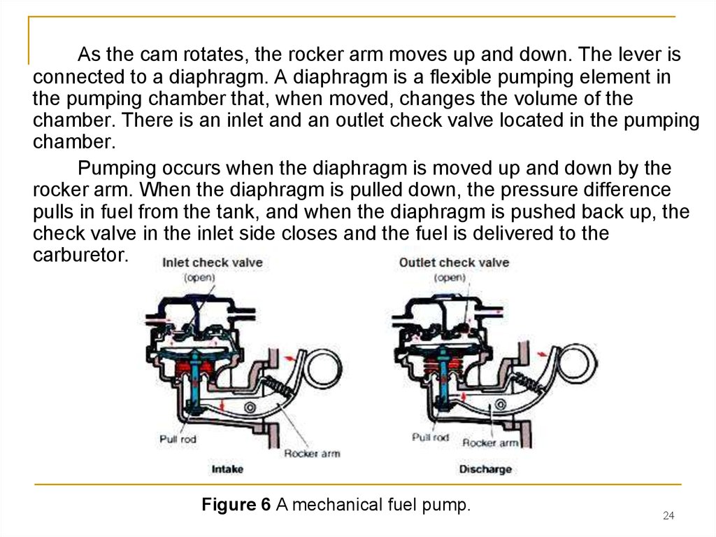
24.
As the cam rotates, the rocker arm moves up and down. The lever isconnected to a diaphragm. A diaphragm is a flexible pumping element in
the pumping chamber that, when moved, changes the volume of the
chamber. There is an inlet and an outlet check valve located in the pumping
chamber.
Pumping occurs when the diaphragm is moved up and down by the
rocker arm. When the diaphragm is pulled down, the pressure difference
pulls in fuel from the tank, and when the diaphragm is pushed back up, the
check valve in the inlet side closes and the fuel is delivered to the
carburetor.
Figure 6 A mechanical fuel pump.
24
25. Vacuum Fuel Pumps
The vacuum fuel pump (Figure 7), also called an impulse fuelpump, uses a diaphragm that’s moved by the pressure differences
of engine vacuum and atmospheric pressure.
It works in the same
manner as the mechanical fuel
pump but instead of a mechanical
lever, the diaphragm is moved by
pressure and vacuum made by the
engine.
Figure 7 A vacuum-operated fuel valve uses engine vacuum to allow fuel to
flow by use of a diaphragm, as shown here.
25
26. Electric fuel pump
The electric fuel pump is operated electronically by the use ofan electric motor and solenoid that pumps the fuel from the fuel tank
to the carburetor (Figure 8).
An electric fuel pump operates only when the power equipment
engine is running, unless it’s bypassed.
Figure 8 A typical electric fuel pump.
26
27. CARBURETOR TYPES AND OPERATION
The carburetor has the task of combining the air and fuel intoa mixture that produces power for the engine.
First, the engine draws in air.
The pressure difference between the outside atmosphere (higher
pressure) and the inside of the cylinder (lower pressure) forces
the air to pass through the carburetor. The air mixes with a
predetermined amount of fuel, which is also moved by pressure
differences, into the air stream of the carburetor venturi.
Carburetors use different fuel metering systems, which
supply fuel for the air–fuel mixture in regulated amounts. These
metering systems are called fuel circuits, and their operating
ranges overlap.
We’ll discuss these circuits as well as the operation of the
common carburetors that you’ll see in power equipment engines.
27
28. Cold Start Systems
For the cold start phase of engine operation, a rich fuelmixture is needed because the engine metal is cold. When the
engine is cold, the air–fuel mixture is also cold and won’t vaporize
or combust readily.
To compensate for this reluctance to burn, the amount of fuel
in proportion to the amount of air must be increased.
This is accomplished by the use of a cold start system. Cold
start systems are designed to provide and control a richer-thannormal air–fuel mixture, which is necessary to quickly start a cold
power equipment engine.
Most carburetor cold-start mixtures are designed to operate at
a ratio of approximately 10:1, that is, 10 parts of air to 1 part of
fuel. Carburetors manufactured today usually include one of two
types of cold start devices.
28
29. Primer Cold Start System
A primer cold start system is a rubber squeeze bulb used to forcefuel into the combustion chamber past the carburetor to help start a cold
engine (Figure 9).
Figure 9 A primer cold start system pushes fuel directly into the engine.
29
30.
There are two different types of the primer cold start system inpower equipment engines:
wet bulb;
dry bulb.
They can be mounted to the side of the carburetor or as a
separate assembly mounted elsewhere in the engine.
To start a cold engine with a wet bulb primer, the operator
squeezes the bulb, which forces fuel out of the bulb-holding chamber
past a check valve through the carburetor and into the engine. When
the bulb is released, fuel is refilled back into the bulb from the fuel
source.
There are two check valves on a wet bulb primer: one to prevent
fuel from entering the engine under low pressure (when the bulb is
released) and one to prevent fuel from entering into the source under
high pressure (when the bulb is being pushed).
When used, the engine receives raw fuel in the intake port for an
easier cold engine start.
The dry bulb primer pushes air into the carburetor bowl, which
increases pressure in the bowl. The increase in pressure forces fuel
through the carburetor and into the engine.
30
31. Choke Plate Cold Start System
The choke plate cold start system is an air restriction systemthat controls the amount of air available during a cold engine start.
This system uses an operator-controlled plate, called a choke
valve, to block air to the carburetor venturi at all throttle openings
(Figure 10).
Figure 10 The choke plate cold start system closes off air to the engine.
31
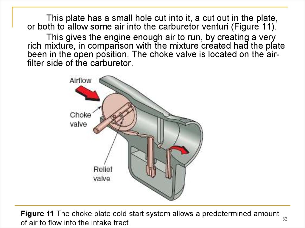
32.
This plate has a small hole cut into it, a cut out in the plate,or both to allow some air into the carburetor venturi (Figure 11).
This gives the engine enough air to run, by creating a very
rich mixture, in comparison with the mixture created had the plate
been in the open position. The choke valve is located on the airfilter side of the carburetor.
Figure 11 The choke plate cold start system allows a predetermined amount
of air to flow into the intake tract.
32
33. Choke Plate Operation
The choke plate can be operated manually or by an automaticchoke, as in some engines. An automatic choke is a valve connected to
a diaphragm or bimetal spring that automatically opens or closes the
choke valve.
The diaphragm-type
automatic choke uses a
diaphragm mounted to the
carburetor (Figure 12). It’s
connected to the choke valve
shaft by a link. A spring under
the diaphragm holds the
choke valve closed when the
engine isn’t running.
Figure 12 A diaphragm type automatic choke and its related components.
33
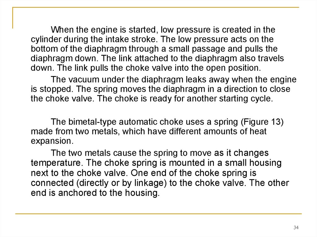
34.
When the engine is started, low pressure is created in thecylinder during the intake stroke. The low pressure acts on the
bottom of the diaphragm through a small passage and pulls the
diaphragm down. The link attached to the diaphragm also travels
down. The link pulls the choke valve into the open position.
The vacuum under the diaphragm leaks away when the engine
is stopped. The spring moves the diaphragm in a direction to close
the choke valve. The choke is ready for another starting cycle.
The bimetal-type automatic choke uses a spring (Figure 13)
made from two metals, which have different amounts of heat
expansion.
The two metals cause the spring to move as it changes
temperature. The choke spring is mounted in a small housing
next to the choke valve. One end of the choke spring is
connected (directly or by linkage) to the choke valve. The other
end is anchored to the housing.
34
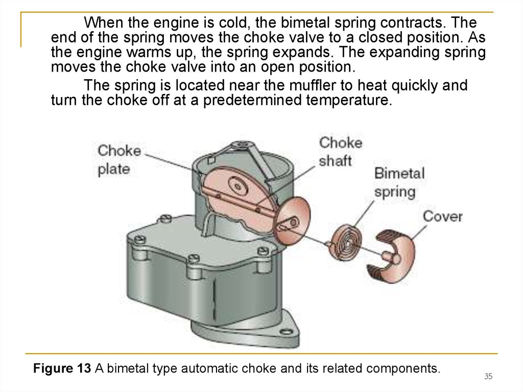
35.
When the engine is cold, the bimetal spring contracts. Theend of the spring moves the choke valve to a closed position. As
the engine warms up, the spring expands. The expanding spring
moves the choke valve into an open position.
The spring is located near the muffler to heat quickly and
turn the choke off at a predetermined temperature.
Figure 13 A bimetal type automatic choke and its related components.
35
36. Types of Carburetors
There are many types of carburetor designs, but as you’velearned, the fundamental operation is the same for each design.
Carburetors must atomize the fuel before the fuel reaches the
engine. Proper atomization ensures that the air–fuel mixture is
vaporized so that the engine performs at its best. Most carburetors
used in power equipment engines have a fixed venturi, meaning that
the venturi remains the same size at all engine running speeds, in
contrast to carburetors used on motorcycles or all-terrain vehicles
(ATVs), where a variable venturi carburetor is used by implementing
a slide that moves up and down at different engine speeds.
The carburetors used in power equipment engines can be
grouped into four categories:
1. Vacuum
2. Float
3. Diaphragm
4. Suction feed diaphragm
36
37. 1. Vacuum Carburetors
The vacuum carburetor, also called the suction carburetor, is acommon carburetor often found installed in smaller, less expensive
engines (Figure 14). A vacuum carburetor uses vacuum to pull fuel out of
the fuel tank and mixes it with air entering the engine. These carburetors
are always mounted on top of the fuel. All vacuum carburetors work the
same basic way.
Figure 14 The vacuum type carburetor uses a simple, one-piece housing. 37
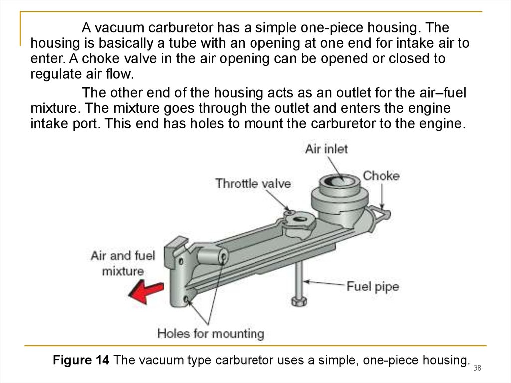
38.
A vacuum carburetor has a simple one-piece housing. Thehousing is basically a tube with an opening at one end for intake air to
enter. A choke valve in the air opening can be opened or closed to
regulate air flow.
The other end of the housing acts as an outlet for the air–fuel
mixture. The mixture goes through the outlet and enters the engine
intake port. This end has holes to mount the carburetor to the engine.
Figure 14 The vacuum type carburetor uses a simple, one-piece housing. 38
39.
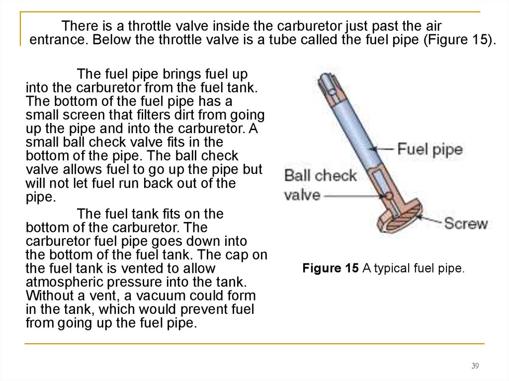
There is a throttle valve inside the carburetor just past the airentrance. Below the throttle valve is a tube called the fuel pipe (Figure 15).
The fuel pipe brings fuel up
into the carburetor from the fuel tank.
The bottom of the fuel pipe has a
small screen that filters dirt from going
up the pipe and into the carburetor. A
small ball check valve fits in the
bottom of the pipe. The ball check
valve allows fuel to go up the pipe but
will not let fuel run back out of the
pipe.
The fuel tank fits on the
bottom of the carburetor. The
carburetor fuel pipe goes down into
the bottom of the fuel tank. The cap on
the fuel tank is vented to allow
atmospheric pressure into the tank.
Without a vent, a vacuum could form
in the tank, which would prevent fuel
from going up the fuel pipe.
Figure 15 A typical fuel pipe.
39
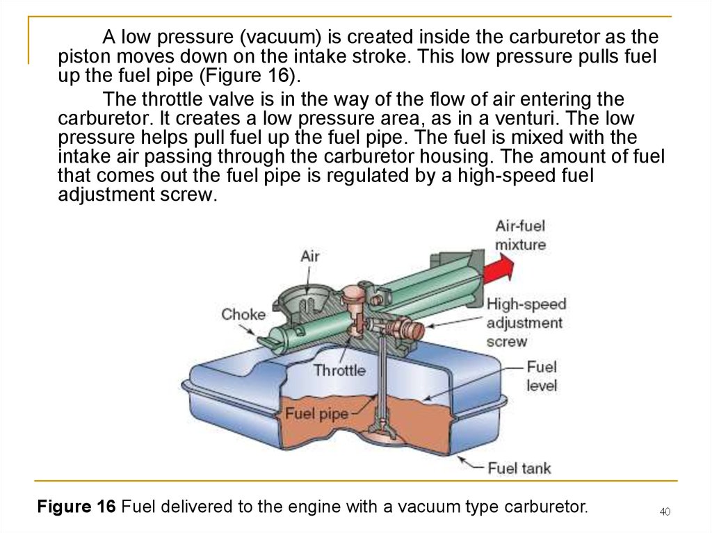
40.
A low pressure (vacuum) is created inside the carburetor as thepiston moves down on the intake stroke. This low pressure pulls fuel
up the fuel pipe (Figure 16).
The throttle valve is in the way of the flow of air entering the
carburetor. It creates a low pressure area, as in a venturi. The low
pressure helps pull fuel up the fuel pipe. The fuel is mixed with the
intake air passing through the carburetor housing. The amount of fuel
that comes out the fuel pipe is regulated by a high-speed fuel
adjustment screw.
Figure 16 Fuel delivered to the engine with a vacuum type carburetor.
40
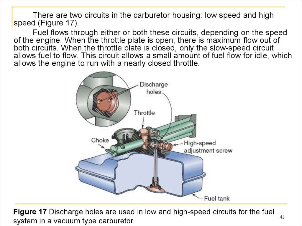
41.
There are two circuits in the carburetor housing: low speed and highspeed (Figure 17).
Fuel flows through either or both these circuits, depending on the speed
of the engine. When the throttle plate is open, there is maximum flow out of
both circuits. When the throttle plate is closed, only the slow-speed circuit
allows fuel to flow. This circuit allows a small amount of fuel flow for idle, which
allows the engine to run with a nearly closed throttle.
Figure 17 Discharge holes are used in low and high-speed circuits for the fuel
system in a vacuum type carburetor.
41
42. 2. Float Carburetors
Many power equipment engines use a float carburetor (Figure 18),which is a carburetor that has an internal fuel storage supply controlled
by a float assembly.
The fuel tank on the float carburetor system is attached to another
part of the engine, often mounted higher than the carburetor.
Gravity causes fuel
to flow from the tank through
a fuel line to the carburetor.
Some engines use a fuel
pump to transfer the fuel from
the tank, to the carburetor. A
float assembly in the
carburetor controls the flow
of fuel from the tank.
Figure 18 A float type carburetor.
42
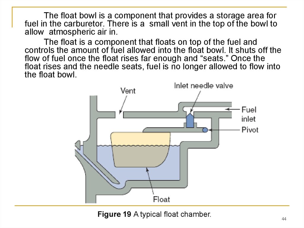
43.
The fuel line from the fuel tank provides fuel to the carburetor.The fuel line is connected to a carburetor fuel inlet fitting. The fuel
flows past an inlet seat. The inlet seat is a carburetor part that
houses and provides a matching seat for the tapered end of a float
needle valve. The fuel goes through the inlet seat into the carburetor
float bowl. The valve is used to allow fuel to flow or stop the flow of
fuel into the float bowl. A float pivots against the needle valve
(Figure 19).
Figure 19 A typical float chamber.
43
44.
The float bowl is a component that provides a storage area forfuel in the carburetor. There is a small vent in the top of the bowl to
allow atmospheric air in.
The float is a component that floats on top of the fuel and
controls the amount of fuel allowed into the float bowl. It shuts off the
flow of fuel once the float rises far enough and “seats.” Once the
float rises and the needle seats, fuel is no longer allowed to flow into
the float bowl.
Figure 19 A typical float chamber.
44
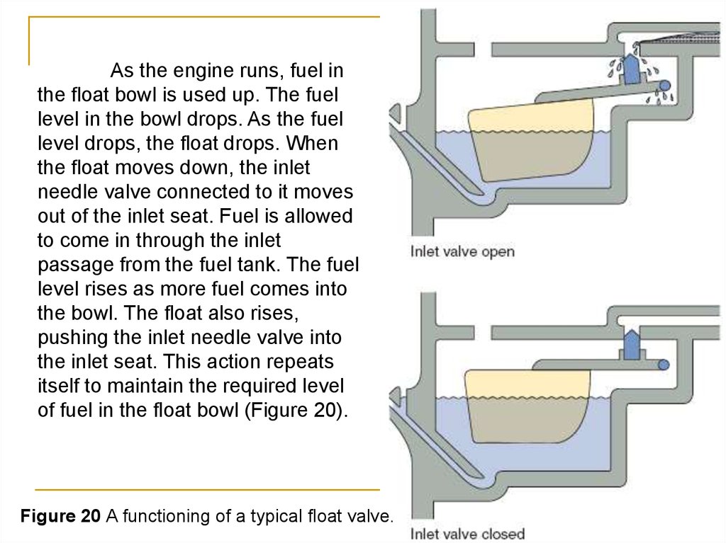
45.
As the engine runs, fuel inthe float bowl is used up. The fuel
level in the bowl drops. As the fuel
level drops, the float drops. When
the float moves down, the inlet
needle valve connected to it moves
out of the inlet seat. Fuel is allowed
to come in through the inlet
passage from the fuel tank. The fuel
level rises as more fuel comes into
the bowl. The float also rises,
pushing the inlet needle valve into
the inlet seat. This action repeats
itself to maintain the required level
of fuel in the float bowl (Figure 20).
Figure 20 A functioning of a typical float valve.
45
46. Float Carburetor Types
All float carburetors use a float to control the fuel level. There are,however, different styles of float carburetors.
These carburetors are identified commonly by the direction of air
flow into the carburetor throat. A carburetor throat is the part of the
carburetor that directs air flow in toward the venturi.
Updraft, downdraft, and sidedraft are common float carburetor designs.
46
47.
An updraft carburetor (Figure 21) is a carburetor in which the airflows into the venturi in an upward direction.
Updraft carburetors are installed commonly in older, larger engines.
Figure 21 An updraft float carburetor system.
47
48.
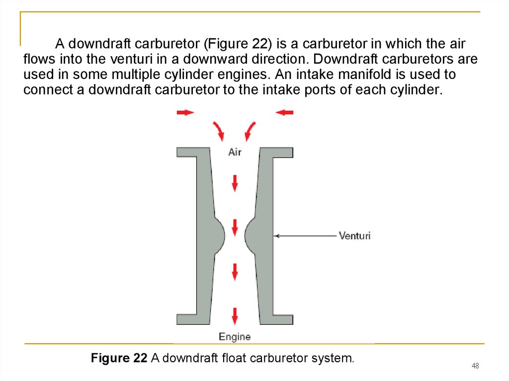
A downdraft carburetor (Figure 22) is a carburetor in which the airflows into the venturi in a downward direction. Downdraft carburetors are
used in some multiple cylinder engines. An intake manifold is used to
connect a downdraft carburetor to the intake ports of each cylinder.
Figure 22 A downdraft float carburetor system.
48
49.
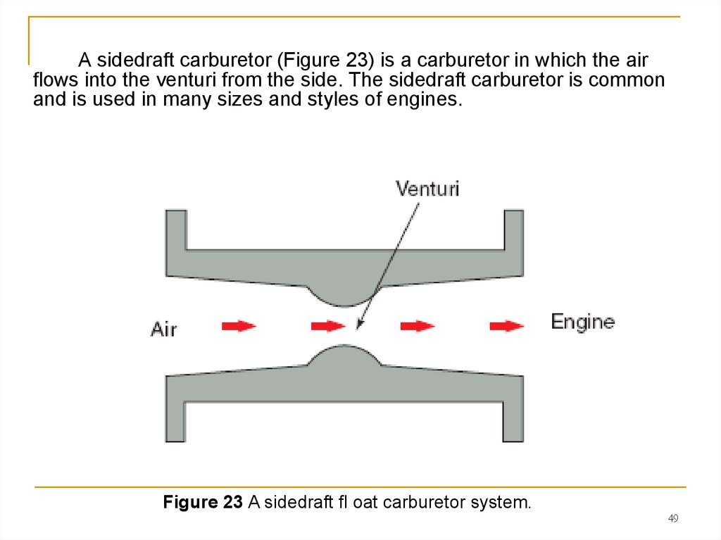
A sidedraft carburetor (Figure 23) is a carburetor in which the airflows into the venturi from the side. The sidedraft carburetor is common
and is used in many sizes and styles of engines.
Figure 23 A sidedraft fl oat carburetor system.
49
50. Float Carburetor Operation
Most float carburetors operate in the same fashion. Theoperation of the carburetor can be divided into different systems:
Float operation
Idle (low-speed) circuit operation
Part throttle circuit operation (transition from low speed
to high speed)
Main (high-speed) circuit operation
50
51.
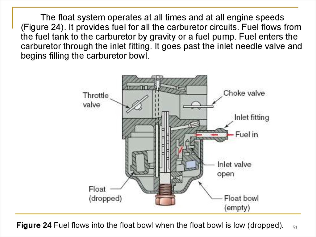
The float system operates at all times and at all engine speeds(Figure 24). It provides fuel for all the carburetor circuits. Fuel flows from
the fuel tank to the carburetor by gravity or a fuel pump. Fuel enters the
carburetor through the inlet fitting. It goes past the inlet needle valve and
begins filling the carburetor bowl.
Figure 24 Fuel flows into the float bowl when the float bowl is low (dropped).
51
52.
As the bowl fills, the float rises, raising the inlet needle valve towardthe inlet seat (Figure 25). When the inlet needle closes, fuel flow into the
bowl stops. Fuel remains at this level until engine operation begins to
draw fuel from the bowl. When the fuel level drops again, the float
moves down, causing the inlet needle valve to move away from the inlet
seat. Fuel again flows into the float bowl. This happens over and over to
provide a constant fuel supply.
Figure 25 When the float bowl is filled, the flow of fuel is stopped.
52
53.
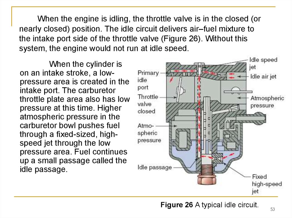
When the engine is idling, the throttle valve is in the closed (ornearly closed) position. The idle circuit delivers air–fuel mixture to
the intake port side of the throttle valve (Figure 26). Without this
system, the engine would not run at idle speed.
When the cylinder is
on an intake stroke, a lowpressure area is created in the
intake port. The carburetor
throttle plate area also has low
pressure at this time. Higher
atmospheric pressure in the
carburetor bowl pushes fuel
through a fixed-sized, highspeed jet through the low
pressure area. Fuel continues
up a small passage called the
idle passage.
Figure 26 A typical idle circuit.
53
54.
The atmospheric pressure from the intake stroke also pulls airinto the throat of the carburetor. Some of this air goes through a
passage called the idle air bleed. As the fuel comes up the idle
passage, it enters the center of the idle speed jet.
Here it mixes with air
from the idle air bleed. The
air–fuel mixture is then
pulled through a passage,
called the primary idle port.
It then goes into the
carburetor throat. Here, it
mixes with air flowing
through the carburetor
throat and goes into the
engine’s cylinder.
Figure 26 A typical idle circuit.
54
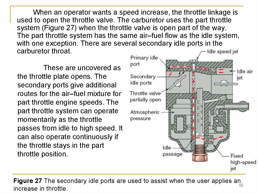
55.
When an operator wants a speed increase, the throttle linkage isused to open the throttle valve. The carburetor uses the part throttle
system (Figure 27) when the throttle valve is open part of the way.
The part throttle system has the same air–fuel flow as the idle system,
with one exception. There are several secondary idle ports in the
carburetor throat.
These are uncovered as
the throttle plate opens. The
secondary ports give additional
routes for the air–fuel mixture for
part throttle engine speeds. The
part throttle system can operate
momentarily as the throttle
passes from idle to high speed. It
can also operate continuously if
the throttle stays in the part
throttle position.
Figure 27 The secondary idle ports are used to assist when the user applies an
55
increase in throttle.
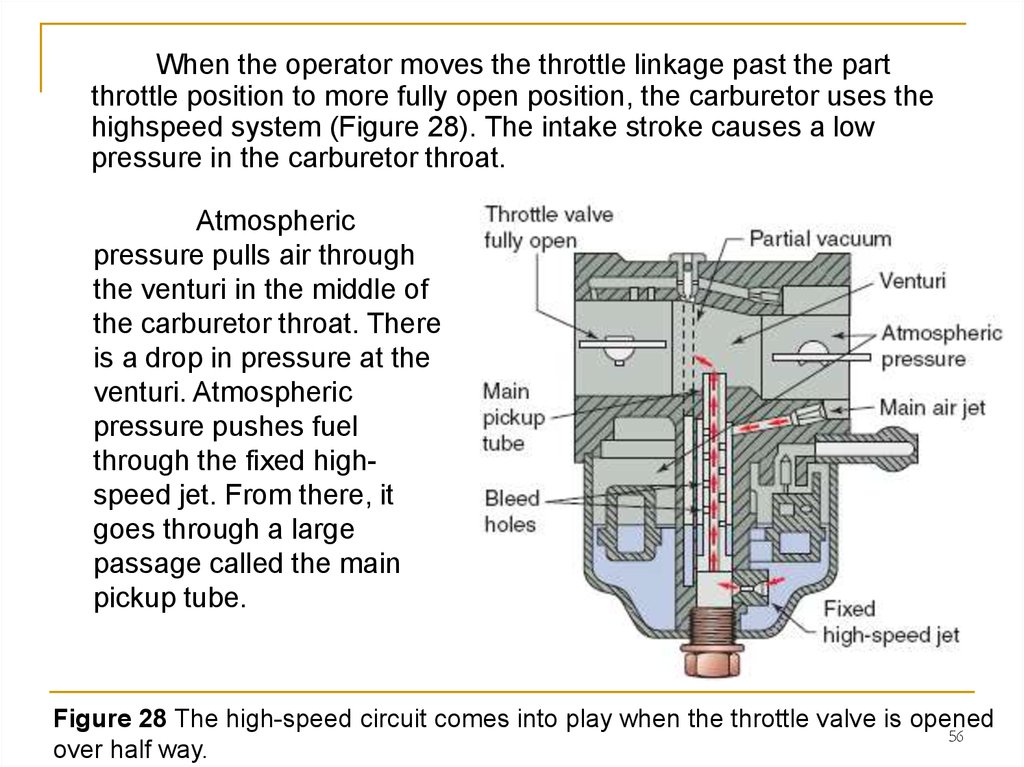
56.
When the operator moves the throttle linkage past the partthrottle position to more fully open position, the carburetor uses the
highspeed system (Figure 28). The intake stroke causes a low
pressure in the carburetor throat.
Atmospheric
pressure pulls air through
the venturi in the middle of
the carburetor throat. There
is a drop in pressure at the
venturi. Atmospheric
pressure pushes fuel
through the fixed highspeed jet. From there, it
goes through a large
passage called the main
pickup tube.
Figure 28 The high-speed circuit comes into play when the throttle valve is opened
56
over half way.
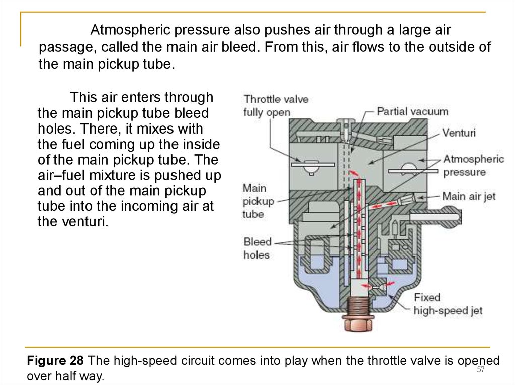
57.
Atmospheric pressure also pushes air through a large airpassage, called the main air bleed. From this, air flows to the outside of
the main pickup tube.
This air enters through
the main pickup tube bleed
holes. There, it mixes with
the fuel coming up the inside
of the main pickup tube. The
air–fuel mixture is pushed up
and out of the main pickup
tube into the incoming air at
the venturi.
Figure 28 The high-speed circuit comes into play when the throttle valve is opened
57
over half way.
58. 3. Diaphragm Carburetors
A diaphragm carburetor (Figure 29) is a carburetor that has a flexiblediaphragm to regulate the amount of fuel available inside the carburetor. It
can be operated in any position.
Float- and vacuumtype carburetors work only in
engines that are used in the
upright position. For this
reason, an engine equipped
with a float or vacuum
carburetor cannot be turned
on its side or upside down, in
which case the float or fuel
tube would not be able to
regulate the fuel level, and the
engine would run out of fuel
and stop.
Figure 29 A diaphragm carburetor can be turned in any angle without impairing
operation
58
59. Diaphragm Carburetor Operation
Handheld outdoor power equipment such as a chainsaws, leafblowers, and string trimmers, which must work in any position, use
engines equipped with diaphragm carburetors, as they can operate in
any position.
The diaphragm
carburetor is, in many ways,
very much the same as a
float carburetor. It has a
throat, throttle valve, and
venturi. But the diaphragm
carburetor does not have a
float bowl.
Figure 29 A diaphragm carburetor can be turned in any angle without impairing
operation
59
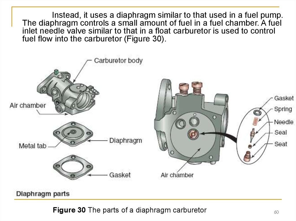
60.
Instead, it uses a diaphragm similar to that used in a fuel pump.The diaphragm controls a small amount of fuel in a fuel chamber. A fuel
inlet needle valve similar to that in a float carburetor is used to control
fuel flow into the carburetor (Figure 30).
Figure 30 The parts of a diaphragm carburetor
60
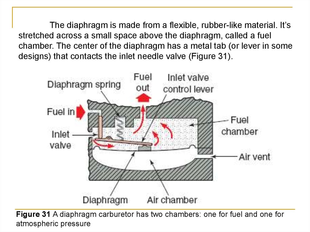
61.
The diaphragm is made from a flexible, rubber-like material. It’sstretched across a small space above the diaphragm, called a fuel
chamber. The center of the diaphragm has a metal tab (or lever in some
designs) that contacts the inlet needle valve (Figure 31).
Figure 31 A diaphragm carburetor has two chambers: one for fuel and one for
atmospheric pressure
62.
The inlet needle valve works the same way as the needle valve ina float carburetor. The space below the diaphragm is called an air
chamber, which has an air vent that allows air at atmospheric pressure
below the diaphragm. The air chamber provides the space for diaphragm
up-and-down movement
Figure 31 A diaphragm carburetor has two chambers: one for fuel and one for
atmospheric pressure
62
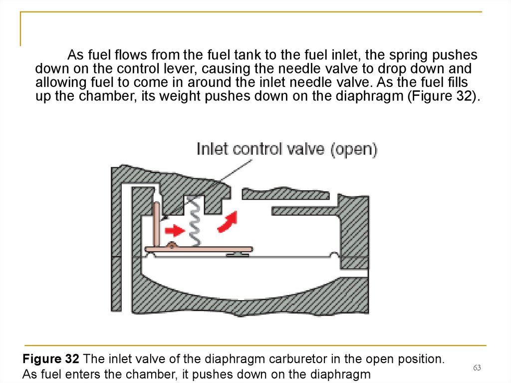
63.
As fuel flows from the fuel tank to the fuel inlet, the spring pushesdown on the control lever, causing the needle valve to drop down and
allowing fuel to come in around the inlet needle valve. As the fuel fills
up the chamber, its weight pushes down on the diaphragm (Figure 32).
Figure 32 The inlet valve of the diaphragm carburetor in the open position.
As fuel enters the chamber, it pushes down on the diaphragm
63
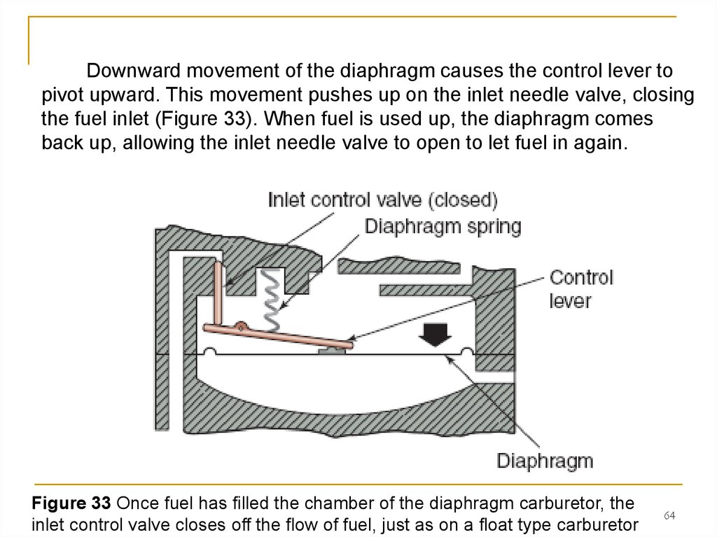
64.
Downward movement of the diaphragm causes the control lever topivot upward. This movement pushes up on the inlet needle valve, closing
the fuel inlet (Figure 33). When fuel is used up, the diaphragm comes
back up, allowing the inlet needle valve to open to let fuel in again.
Figure 33 Once fuel has filled the chamber of the diaphragm carburetor, the
inlet control valve closes off the flow of fuel, just as on a float type carburetor
64
65. Modes of Operation of a Diaphragm Carburetor
Just as with everyother type of carburetor,
the diaphragm
carburetor provides the
correct air–fuel mixtures
for several modes
(circuits) of operation
(Figure 34).
Figure 34 The various circuits of a diaphragm carburetor
65
66. ■ Cold starting
When the engine is cold, arich mixture is required for starting.
The choke system has a valve in
the carburetor throat, as we had
discussed earlier in this chapter. In
the choke mode, the choke valve
is closed.
The only air that can get into the engine enters through openings
around the choke valve. When the engine is cranked during starting, the
intake stroke creates a low pressure in the venturi. The low pressure
pulls fuel from the diaphragm chamber up the main nozzle. The fuel
mixes with the air that passes around the choke valve. A very rich air–
fuel mixture is used to start the cold engine.
66
67. ■ Idle
During idle speeds, only a smallamount of fuel is needed to keep the
engine running. The throttle valve is
almost closed during idle.
A small idle discharge port is
located on the engine side of the closed
throttle valve. The low pressure in this
area pulls fuel from the diaphragm
chamber. Fuel goes past an idle
adjusting screw and is delivered behind
the throttle valve.
The fuel is mixed with air that gets
through the almost closed throttle
valve. Additional air comes through an
idle air bleed passage.
The idle adjusting screw adjusts
the amount of fuel that is delivered out
the idle discharge port.
■ Idle
67
68. ■ Intermediate speed
When the throttle valve is movedpast the idle position, it uncovers one
more discharge port, called the
intermediate port. It provide more fuel
to mix with the air flowing into the
engine.
The fuel flows from the
diaphragm chamber past the idle
mixture adjusting screw.
Fuel and air flows are the same
as in the idle mode.
The additional fuel from the
intermediate ports allows the engine to
operate at higher speeds.
68
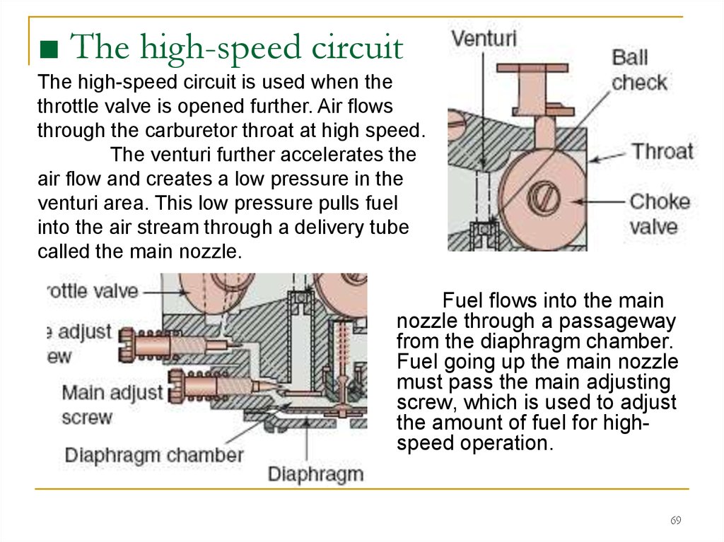
69.
■ The high-speed circuitThe high-speed circuit is used when the
throttle valve is opened further. Air flows
through the carburetor throat at high speed.
The venturi further accelerates the
air flow and creates a low pressure in the
venturi area. This low pressure pulls fuel
into the air stream through a delivery tube
called the main nozzle.
Fuel flows into the main
nozzle through a passageway
from the diaphragm chamber.
Fuel going up the main nozzle
must pass the main adjusting
screw, which is used to adjust
the amount of fuel for highspeed operation.
69
70. 4.Suction Feed Diaphragm Carburetors
The suction feeddiaphragm carburetor is a
carburetor that combines
the features of a vacuum
carburetor and the impulse
fuel pump (Figure 35).
This carburetor is
used primarily in four-stroke
engines. These engines are
not usually used in a variety
of positions.
The carburetor is
mounted on the top of the
fuel tank. It meters fuel the
same way as the vacuum
carburetor.
Figure 35 The suction feed diaphragm carburetor is one that combines the
features of a vacuum carburetor and the impulse fuel pump
70
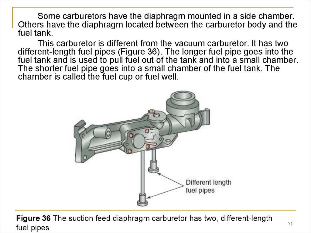
71.
Some carburetors have the diaphragm mounted in a side chamber.Others have the diaphragm located between the carburetor body and the
fuel tank.
This carburetor is different from the vacuum carburetor. It has two
different-length fuel pipes (Figure 36). The longer fuel pipe goes into the
fuel tank and is used to pull fuel out of the tank and into a small chamber.
The shorter fuel pipe goes into a small chamber of the fuel tank. The
chamber is called the fuel cup or fuel well.
Figure 36 The suction feed diaphragm carburetor has two, different-length
fuel pipes
71
72.
A diaphragm fits between the carburetor and the fuel cup. Thediaphragm works like an impulse fuel pump, transferring fuel between the
tank and the fuel cup (Figure 37). This system gives a constant level of fuel,
regardless of fuel tank level.
A pulse hose connects the pumping chamber to the intake manifold
(or crankcase in some designs). When the engine is running, the pulse
hose transmits a pulse to the diaphragm chamber.
The diaphragm moves up and down with the pressure pulses,
pumping fuel up the long fuel pipe into the fuel tank cup. Fuel goes out of
the fuel cup into the venturi through the short fuel pipe.
Figure 37 The suction feed carburetor drawing fuel from the fuel tank.
72
73.
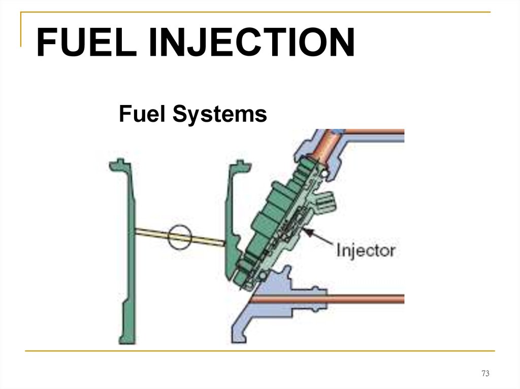
FUEL INJECTIONFuel Systems
73
74. FUEL INJECTION
Fuel injection is the most modern method for carburetion intoday’s power equipment engines. The purpose of fuel injection is to
allow a precise metering of air–fuel mixture ratios at any given engine
condition.
This results in the
engine getting only the
amount of fuel it needs
at all times, instead of
a preset amount being
delivered at all times,
as with traditional
carburetors. Other than
the method of getting
fuel into the engine, the
basic components of
this system aren’t
much different from
those of a standard
carburetor engine.
74
75. FUEL INJECTION
In today’s power equipment engines, fuel injection is becomingpopular as using it leads to easier compliance with the strict guidelines
of the environmental requirements.
The primary
advantage of fuel
injection over
traditional
carburetion is the
ability of a fuel
injected engine to
automatically adjust
to the constantly
changing
atmospheric
conditions to which
it’s exposed.
75
76.
Conditions such as temperature, humidity, and altitude affecttraditional carburetion, altering the efficiency of a carbureted power
equipment engine, unless one were to make physical adjustments to the
carburetor settings. But with an engine using fuel injection systems, these
conditions are compensated for by the use of sensors found within the
fuel injection system.
76
77.
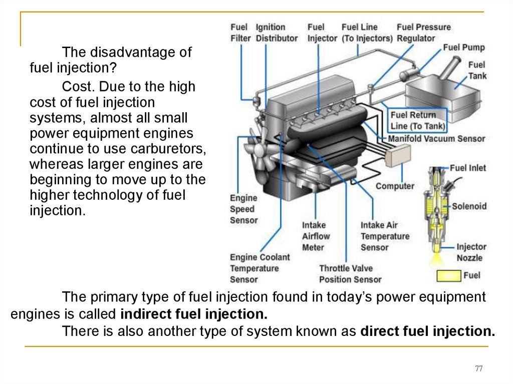
The disadvantage offuel injection?
Cost. Due to the high
cost of fuel injection
systems, almost all small
power equipment engines
continue to use carburetors,
whereas larger engines are
beginning to move up to the
higher technology of fuel
injection.
The primary type of fuel injection found in today’s power equipment
engines is called indirect fuel injection.
There is also another type of system known as direct fuel injection.
77
78. Direct Fuel Injection
With the direct fuel injection system, fuel is injected directly intothe combustion chamber. This type of fuel injection is found primarily in
diesel engines and not generally found in power equipment engines.
The direct system
injects an extremely fine
mist of fuel into the
combustion chamber just
prior to the top-dead center
(TDC) of the engine’s
compression stroke.
78
79. Indirect Fuel Injection
The indirect fuel injection system is the most common type of fuelinjection system found in power equipment engines. When an indirect fuel
injection system is used, fuel is injected into the intake tract before the intake
valve.
79
80. Indirect Fuel Injection
All modern fuel-injected power equipment engines use a type ofelectronic fuel injection (EFI).
Some manufacturers may use
different terms to refer to EFI:
- computerized fuel injection (CFI) or
- programmed fuel injection (PGM-FI).
All these systems use an electronic control module (ECM) to control
the amount of fuel being delivered to the engine.
Indirect EFI systems give
engines the ability to provide
excellent performance as well as
meet future EPA (Environment
Protection Agency) standards—
standards that are getting tougher
to achieve with each passing year.
80
81. Fuel Injection System Сomponents
Although many small power equipment engines don’t use fuel injectionnow, their use in future is inevitable. Therefore, we’ll summarize a
description of the components found in a typical EFI system.
Let’s start our discussion on EFI-related system components with the
area of fuel delivery.
81
82. Fuel Pumps
Fuel pumps used with electronic fuel-injected power equipmentengines have three primary requirements:
■ They must be electric powered.
■ They must have the ability to handle a high volume of fuel.
■ They must have the ability to supply high pressure to the injectors.
.
Many modern power equipment engine
EFI fuel pumps are located inside the fuel
tank of the power equipment engine to save
space as well as to prevent vapor lock, a
condition that is caused when gasoline
overheats and begins to actually boil within
the fuel pump.
An ECM (Electronic Control Module)
controls the operation of the fuel pump. The
fuel pump will generally operate for a couple
of seconds after the key is first turned on to
pressurize the fuel injectors.
82
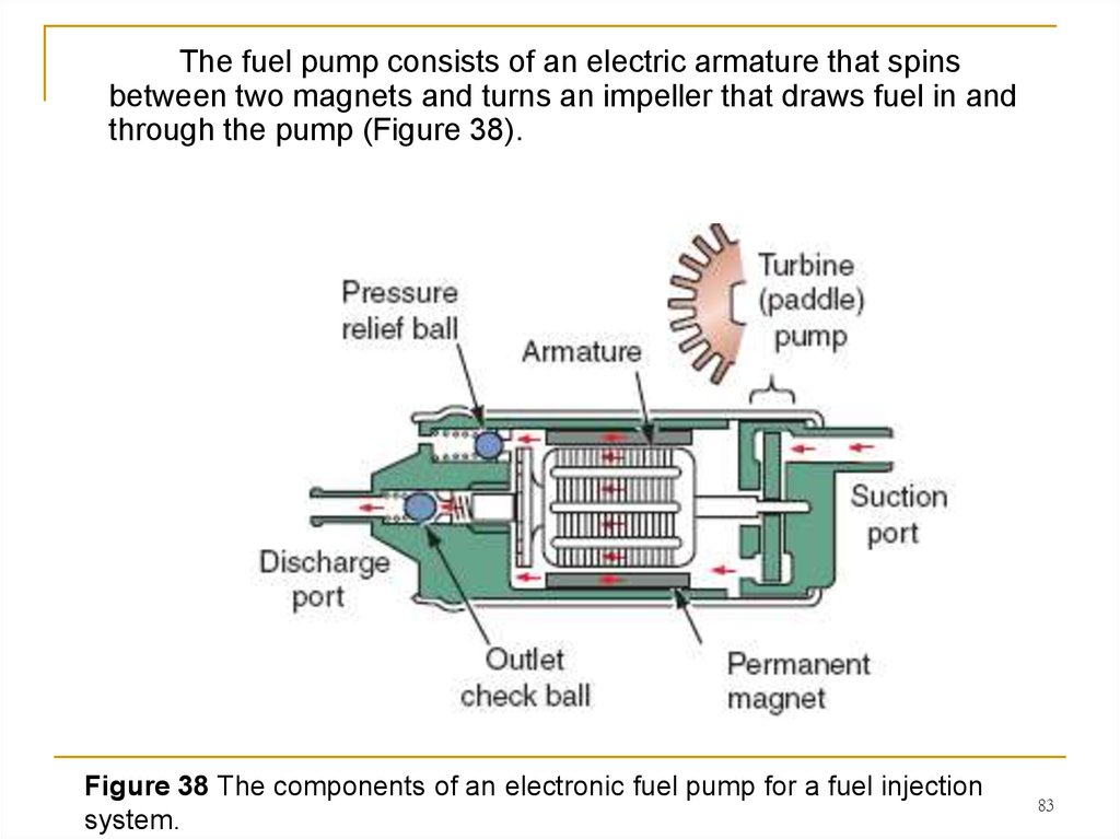
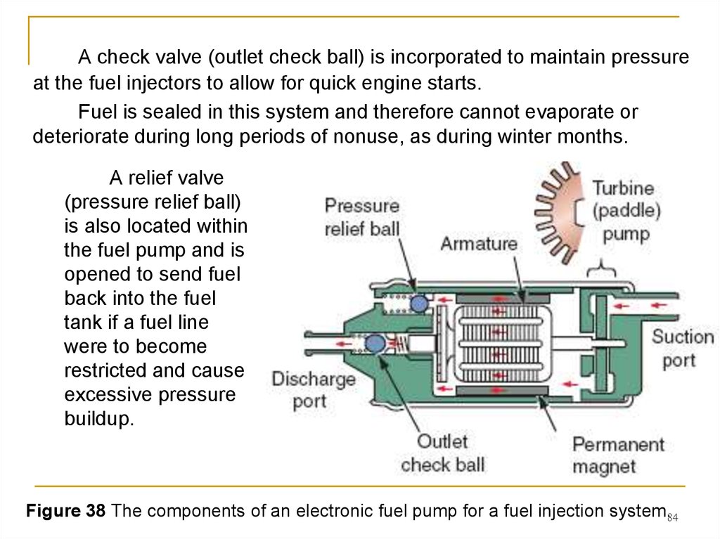
83.
The fuel pump consists of an electric armature that spinsbetween two magnets and turns an impeller that draws fuel in and
through the pump (Figure 38).
Figure 38 The components of an electronic fuel pump for a fuel injection
system.
83
84.
A check valve (outlet check ball) is incorporated to maintain pressureat the fuel injectors to allow for quick engine starts.
Fuel is sealed in this system and therefore cannot evaporate or
deteriorate during long periods of nonuse, as during winter months.
A relief valve
(pressure relief ball)
is also located within
the fuel pump and is
opened to send fuel
back into the fuel
tank if a fuel line
were to become
restricted and cause
excessive pressure
buildup.
Figure 38 The components of an electronic fuel pump for a fuel injection system.84
85. Fuel Filters
There are generally at least two fuel filters used in EFI systems.Before fuel enters the fuel
pump, it must go through a mesh
filter that prevents grit and rust from
entering the pump and damaging it.
Another filter used is a large
inline type and can be mounted
inside or outside the fuel tank
(Figure 39). The operation of fuel
filters is critical in a fuel-injected
system because clogged fuel
injectors won’t function properly.
Figure 39 The fuel filters located inside the fuel tank.
85
86. Fuel Lines
EFI systems use special, high-pressure fuel lines from the fuelpump to the injectors, which can be damaged by mishandling due to
excessive bending or stretching.
The damage in
many cases will be
internal and therefore
you’ll not see it until
the line breaks under
pressure. When
servicing EFI power
equipment engines,
be sure to adhere to
the appropriate
service manual to
avoid damaging the
fuel lines.
86
87. Fuel Pressure Regulators
The fuelpressure regulator
maintains correct fuel
pressure and keeps it
above the pressure
of the intake
manifold. Excessive
pressure is returned
to the fuel tank by a
separate return hose
(Figure 40).
Figure 40 A fuel pressure regulator is used to maintain correct fuel pressure
and keep it above the pressure of the intake manifold.
87
88. Fuel Injectors
The fuel injector is an electronically operated solenoid that turnsfuel on and off (Figure 41).
Inside the injector, there’s a spring-loaded plunger that closes
against a valve seat. Once seated, the flow of fuel is blocked. When the
solenoid coil within the injector assembly lifts the plunger, the
pressurized fuel sprays into the cylinder. A battery supplies the power
for the solenoid coil.
Figure 41 The fuel injector is a solenoid that is either on (fuel flows) or off (fuel
does not flow).
88
89.
The fuel injectors generally closed and are either fully closed or fullyopen. The ECM “tells” the fuel injector when to turn on and off. The
control unit also determines how long the injector must stay on, therefore
telling the injector how much fuel has been injected into the engine.
This is known as injector discharge duration. The length of time
for which the fuel injector is turned on is known as discharge duration.
The ECM controls the ground side of the injector, therefore making
the injectors “switch to ground circuits.” Each injector is controlled by the
ECM, and fuel is delivered to the cylinder only as it’s needed. This is
known as sequential fuel injection.
Three factors influence fuel atomization in an EFI system:
- the shape of the injector,
- fuel pressure, and
- turbulence in the air intake tract.
89
90.
Fuel injector tip openings are designed to provide a spraypattern that atomizes the fuel to help it mix with the incoming air.
There are different types of fuel injector tips, the most common
having a single outlet, although some engines use multiple outlets
(Figure 42). These outlet designs are used to vary the spray pattern
to the manufacturer’s design needs for different performance
requirements as well as manufacturing costs.
Figure 42 Various types of tips can be found on a fuel injector. Decisions on the
90
type of injector to be used can be based on intended use as well as cost.
91. ECM
The heart of all fuel injection systems is the ECM. The ECMreceives signals from all the EFI system sensors, processes them,
and transmits programmed electrical pulses to the fuel injectors.
Both incoming and outgoing signals are sent through a wiring
harness and a multiple-pin connector. The ECM uses a
microcomputer to process data and control the operation of the fuel
injectors, ignition spark and timing, and the fuel pump.
The
ECM receives information from basic input sensors and determines
what, when, why, and how long the various operation steps need to
be controlled.
Depending on the manufacturer, an ECM can also be called an
electronic control unit (ECU).
91
92. ECM Inputs and Outputs
The ECM has three types of inputs (Figure 43):■ Basic
■ Correction
■ Control
Figure 43. Typical inputs for an electronic fuel injection
92
93. ECM Inputs and Outputs
The basic inputs provide information that the ECM needs to select aparticular mixture control map (most EFI systems have at least two
maps). The ECM then selects the basic fuel discharge duration from the
chosen map. Basic inputs include ignition pulse, camshaft position
sensor, throttle position sensor, and the vacuum pressure in the intake
manifold [manifold absolute pressure (MAP) sensor].
Figure 43. Typical inputs for an electronic fuel injection
93
94.
The correction inputs provide the information that the ECM needsto adjust the basic fuel discharge duration. Typical correction inputs
would include engine temperature, intake air temperature, barometric
pressure (BARO), and vehicle speed.
The control inputs provide the information that the ECM needs to
adjust engine operation. These inputs would be the oxygen sensor and
knock sensor. A bank angle sensor is used often in power equipment
engines to cut off electrical power to the ECM in the case of the
machine tipping over. Bank angle sensors are designed to stop the
engine.
ECM outputs include the fuel injection, ignition spark as well as
the operation of the fuel pump and cooling fan in liquid-cooled
machines.
94
95. Sensors
Various sensors monitor the engine and atmosphericconditions such as throttle position, engine revolutions per minute
(rpm), engine and intake air temperature, vehicle speed and MAP
(which is calculated into air density), coolant temperature, and piston
position.
These
sensors assist in all
aspects of EFI and
send information to
the ECM to allow the
engine to run as
efficiently as possible.
95
96. Throttle Body
Engines with EFI mayhave one throttle valve for each
cylinder. The throttle body
contains the injector as well as a
butterfly valve (Figure 44). Power
equipment engines with EFI don’t
need to depend on the Venturi
effect because of the fuel injector
delivery of a precise amount of
fuel at any given time, unlike a
carbureted power equipment
engine that will receive the same
amount of fuel at all throttle
openings.
Figure 44 A throttle body for an electronic fuel injection (EFI) system along with
96
an illustration of a fuel injector and the inlet port of the throttle body.
97. EFI Self-Diagnostics
Most modern power equipment engines that use EFI have aself-diagnostic system incorporated to assist technicians when
problems arise. Various components on EFI are monitored
continuously by the self-diagnosis function and if the ECM notices a
fault, a light comes on within the dashboard of the machine. This light
is sometimes called the “check engine” light or the “FI” light. Some
manufacturers call this light by the term officially used in the
automotive industry, which is the malfunction indicator lamp (MIL)
(Figure 45), and depending on the severity of the fault, may give a
warning to the user.
In other cases, the engine may go
into a fail-safe operation mode, which allows
the engine to continue to run but at a
reduced performance level or stop
completely, depending on the severity of the
fault, such as when an electrical-related
problem is detected by the system sensors.
The MIL is used to detect and assist in
diagnosing any EFI-related, electrical failure.
Figure 45 The malfunction indicator light (MIL) will let
97
a user know if a failure is detected in the EFI system.
98. Basic Operation of the Fuel Injection System
In a typical EFI system, the ECM must “know” the amount of airentering the engine so that it can supply the stoichiometric air–fuel
ratio.
Most EFI systems have a MAP sensor to allow the computer to
calculate the amount of air entering the engine from the MAP and
engine rpm input signals. The MAP sensor sends a signal relating to
the pressure inside the intake manifold to the ECM.
The ignition pickup or crankshaft position sensor supplies an
rpm signal to the computer.
The computer must have accurate signals from these inputs to
maintain the stoichiometric air–fuel ratio.
Other inputs are used by the computer to fine-tune the air–fuel
ratio through electronic feedback.
98
99. Electronic feedback and closed loop
Electronic feedback means the system is self-regulating andthe ECM is controlling the injectors on the basis of operating
conditions rather than on preprogrammed instructions.
As an example of a feedback loop used in many EFI systems,
the ECM reads signals from an oxygen sensor, varies the pulse
width of the injectors, and again reads the signals from the oxygen
sensor. This cycle is repeated until the injectors are pulsed for just
the amount of time needed to get the proper amount of oxygen into
the exhaust stream.
While this interaction is occurring, the system is operating in a
closed loop. During the closed-loop mode, sensor inputs are sent
to the ECM; the ECM compares the values with those in its
programs and then reacts to the information to adjust the air–fuel
ratio and other engine systems.
99
100. Control loops and catalytic converters
When conditions such as starting or wideopen throttle demandthat the signals from the oxygen sensor be ignored, the system
operates in an open loop. During open loop, injector pulse length is
controlled by set parameters contained in the ECM’s memory.
Systems with oxygen sensors may also go into the open-loop mode
while idling or at any other time that the oxygen sensor cools off
enough to stop sending a good signal, and at wide-open throttle.
The basic purpose of these control loops is to create an ideal
air–fuel ratio, which allows engines using catalytic converters to
operate at maximum efficiency while giving the best fuel mileage
and performance possible.
A catalytic converter is a device used to reduce the toxicity of
emissions from an engine.
100
101. Summary
■ The primary principles of carburetor operation areatomization, the process of combining air and fuel to create a
mixture of liquid droplets suspended in air, and the Venturi principle,
which states that a gas or liquid that’s flowing through a narroweddown section of a passage will increase in speed and decrease in
pressure compared with its speed and pressure in wider sections of
the passageway.
■ Each type of carburetor has different components that
function similarly.
■ The purpose of fuel injection is to allow an extremely precise
metering of air–fuel mixture ratios at any given engine and
atmospheric condition.
101
102. Wankel engine
The Wankel engine is a type ofinternal combustion engine using an
eccentric rotary design to convert
pressure into a rotating motion instead
of using reciprocating pistons.
Its four-stroke cycle takes
place in a space between the inside of
an
oval-like
epitrochoid-shaped
housing and a rotor that is similar in
shape to a Reuleaux triangle but with
sides that are somewhat flatter.
The very compact Wankel
engine delivers smooth high-rpm
power. It is commonly called a rotary
engine, though this name applies also
to other completely different designs.
A cut-away of a Wankel engine shown at the
Deutsches Museum in Munich, Germany
103.
Wankel engineThe engine was invented by German
engineer Felix Wankel. He received his first
patent for the engine in 1929, began
development in the early 1950s at NSU,
completing a working prototype in 1957.
NSU then licensed the concept to
companies around the world, which have
continued to improve the design.
Thanks to their compact design,
Wankel rotary engines have been installed
in a variety of vehicles and devices
including automobiles, motorcycles, racers,
aircraft, go-karts, jet skis, snowmobiles,
chain saws, and auxiliary power units.
The Mazda RX-8, a sports car
powered by a Wankel engine
Norton Classic air-cooled twin-rotor
motorcycle
104. Design
In the Wankel engine, the fourstrokes of a typical Otto cycle occur in the
space between a three-sided symmetric
rotor and the inside of a housing. In the
basic single-rotor Wankel engine, the
oval-like epitrochoid-shaped housing
surrounds a rotor which is triangular with
bow-shaped flanks.
The theoretical shape of the rotor
between the fixed corners is the result of
a minimization of the volume of the
geometric combustion chamber and a
maximization of the compression ratio,
respectively. The symmetric curve
connecting two arbitrary apexes of the
rotor is maximized in the direction of the
inner housing shape with the constraint
that it not touch the housing at any angle
of rotation.
https://en.wikipedia.org/wiki/Wankel_engine#/medi
a/File:Wankel_Cycle_anim_en.gif
105.
DesignThe central drive shaft 8, called the
eccentric shaft or E-shaft, passes through the
center of the rotor 6 and is supported by fixed
bearings (not shown).
The rotor 6 ride on eccentrics (analogous
to crank) integral to the eccentric shaft
(analogous to a crankshaft). The rotor both rotate
around the eccentric and make orbital
revolutions around the eccentric shaft. Seals at
the corners of the rotor seal against the
periphery of the housing, dividing it into three
moving combustion chambers 4.
The rotation of rotor on it own axis is
caused and controlled by a pair of synchronizing
gears. A fixed gear 5 mounted on one side of the
rotor housing engages a ring gear 7 attached to
the rotor and ensures the rotor moves exactly 1/3
turn for each turn of the eccentric shaft 8. The
power output of the engine is not transmitted
through the synchronizing gears. The force of
gas pressure on the rotor (to a first
approximation) goes directly to the center of the
eccentric part of the output shaft.
106.
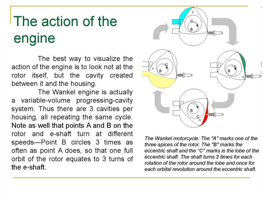
The action of theengine
The best way to visualize the
action of the engine is to look not at the
rotor itself, but the cavity created
between it and the housing.
The Wankel engine is actually
a variable-volume progressing-cavity
system. Thus there are 3 cavities per
housing, all repeating the same cycle.
Note as well that points A and B on the
rotor and e-shaft turn at different
speeds—Point B circles 3 times as
often as point A does, so that one full
orbit of the rotor equates to 3 turns of
the e-shaft.
С
B
С
С
B
B
B
С
The Wankel motorcycle: The "A" marks one of the
three apices of the rotor. The "B" marks the
eccentric shaft and the “C" marks is the lobe of the
eccentric shaft. The shaft turns 3 times for each
rotation of the rotor around the lobe and once for
each orbital revolution around the eccentric shaft.
107.
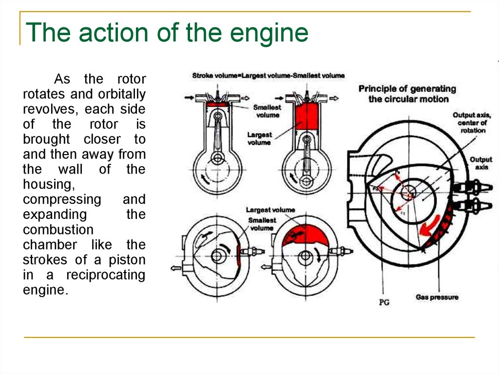
The action of the engineAs the rotor
rotates and orbitally
revolves, each side
of the rotor is
brought closer to
and then away from
the wall of the
housing,
compressing and
expanding
the
combustion
chamber like the
strokes of a piston
in a reciprocating
engine.
108.
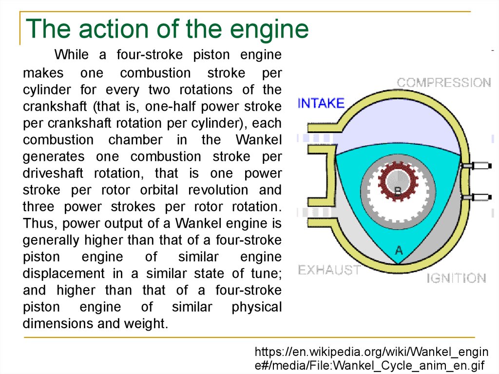
The action of the engineWhile a four-stroke piston engine
makes one combustion stroke per
cylinder for every two rotations of the
crankshaft (that is, one-half power stroke
per crankshaft rotation per cylinder), each
combustion chamber in the Wankel
generates one combustion stroke per
driveshaft rotation, that is one power
stroke per rotor orbital revolution and
three power strokes per rotor rotation.
Thus, power output of a Wankel engine is
generally higher than that of a four-stroke
piston
engine
of
similar
engine
displacement in a similar state of tune;
and higher than that of a four-stroke
piston engine of similar physical
dimensions and weight.
https://en.wikipedia.org/wiki/Wankel_engin
e#/media/File:Wankel_Cycle_anim_en.gif
109.
Wankel engines also generallyhave a much higher redline than a
reciprocating engine of similar power
output. This is in part because the
smoothness inherent in circular motion,
but especially because they do not
have highly stressed parts such as a
crankshaft
or
connecting
rods.
Eccentric shafts do not have the stressraising internal corners of crankshafts.
The redline of a rotary engine is limited
by wear of the synchronizing gears.
Hardened steel gears are used for
extended operation above 7000 or
8000 rpm. Mazda Wankel engines in
auto racing are operated above 10,000
rpm. In aircraft they are used
conservatively, up to 6500 or 7500 rpm.
110.
National agencies that tax automobiles according to displacementand regulatory bodies in automobile racing variously consider the
Wankel engine to be equivalent to a four-stroke engine of 1.5 to 2 times
the displacement; some racing series ban it altogether.