

 informatics
Similar presentations:


")
Number Systems and Codes. Digital Electronic Signals and Switches
1.
Number Systems and Codes.Digital Electronic Signals and
Switches
Lecture 1
Digital Electronics
2.
Course MaterialsAll needed Software and course materials will
be located on Canvas.
◻ Materials that are used in this slides are taken
from the textbook “Digital Electronics A
Practical Approach with VHDL” by William
Kleitz
◻
3.
Number Systems and Codes4.
INTRODUCTION◻
Digital circuitry is the foundation of digital
computers
◻ Home appliances, alarm systems
◻ heating systems, automated machine control
◻ inventory management, medical electronics, etc…
◻
Digital electronics evolved from transistor
circuitry
◻ easily be fabricated
◻ designed to output one of two voltage levels
■ 1 - HIGH (usually +5 volts)
■ 0 – LOW (usually 0 Volts)
5.
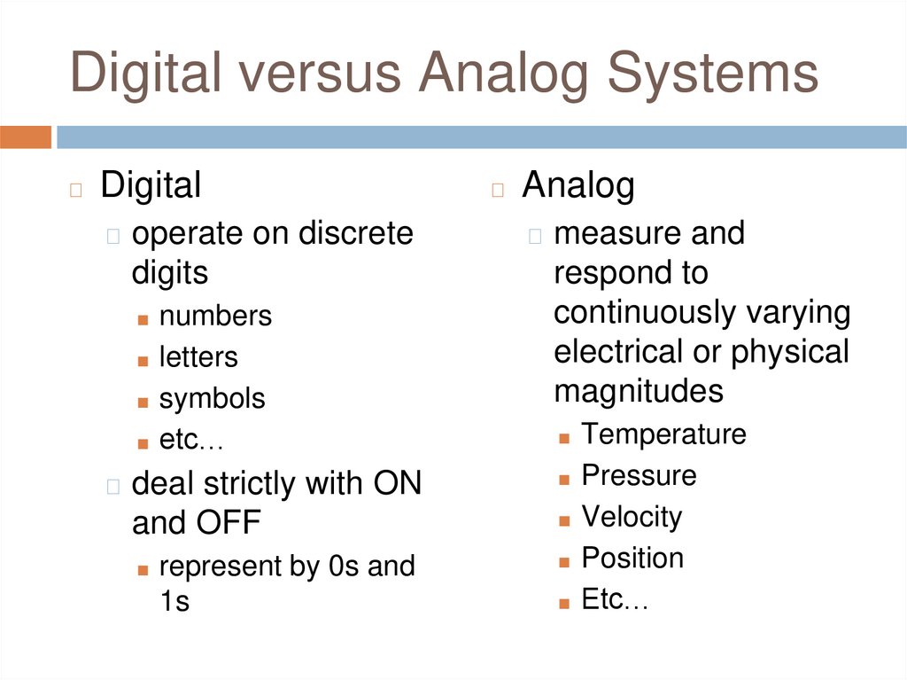
Digital versus Analog Systems◻
Digital
◻ operate on discrete
digits
◻
Analog
◻ measure and
■ symbols
respond to
continuously varying
electrical or physical
magnitudes
■ etc…
■ Temperature
■ numbers
■ letters
◻ deal strictly with ON
■ Pressure
and OFF
■ Velocity
■ represent by 0s and
■ Position
1s
■ Etc…
6.
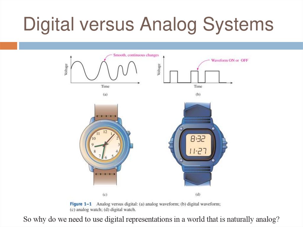
Digital versus Analog SystemsSo why do we need to use digital representations in a world that is naturally analog?
7.
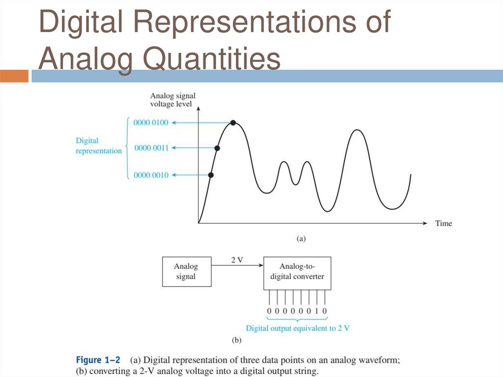
Digital Representations ofAnalog Quantities
8.
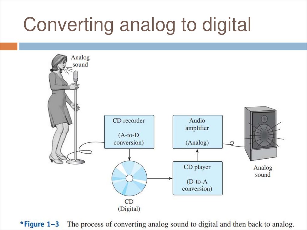
Converting analog to digital9.
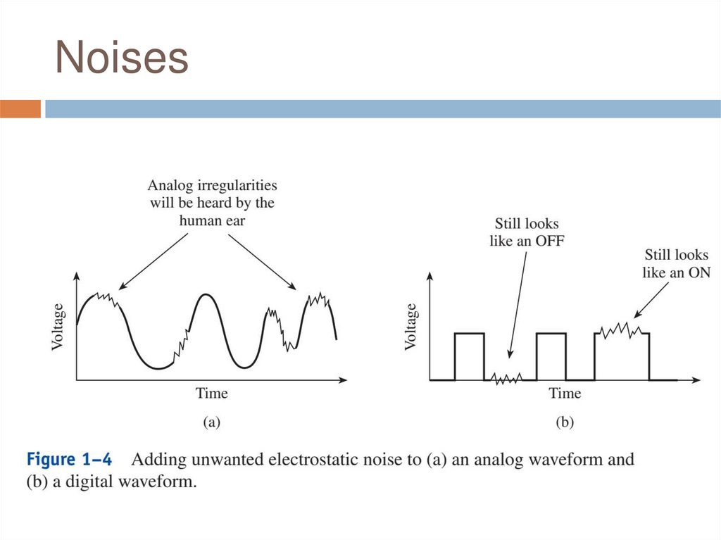
Noises10.
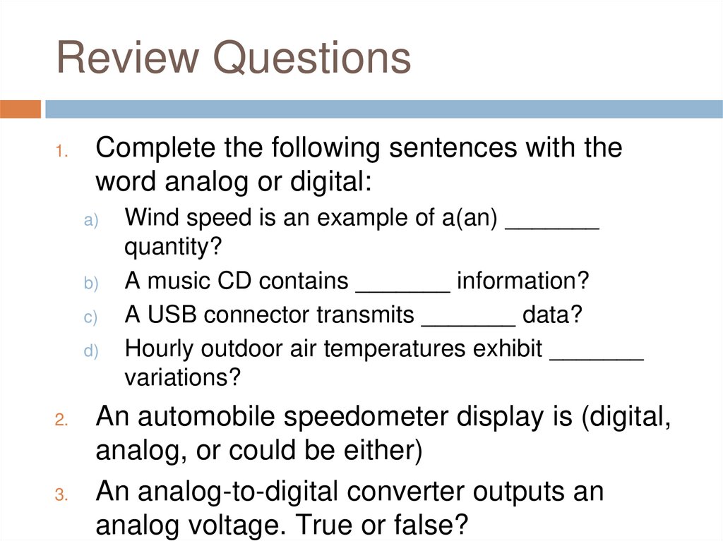
Review Questions1.
Complete the following sentences with the
word analog or digital:
a)
b)
c)
d)
2.
3.
Wind speed is an example of a(an) _______
quantity?
A music CD contains _______ information?
A USB connector transmits _______ data?
Hourly outdoor air temperatures exhibit _______
variations?
An automobile speedometer display is (digital,
analog, or could be either)
An analog-to-digital converter outputs an
analog voltage. True or false?
11.
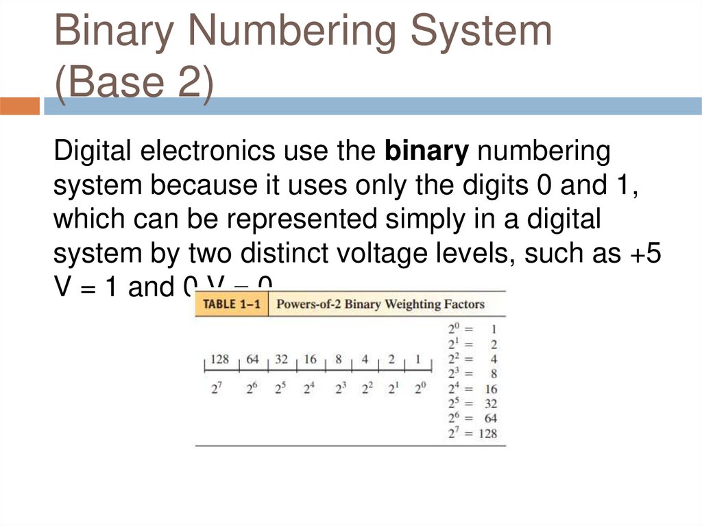
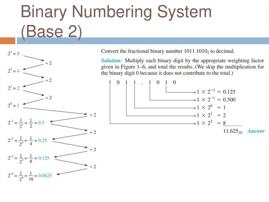
Binary Numbering System(Base 2)
Digital electronics use the binary numbering
system because it uses only the digits 0 and 1,
which can be represented simply in a digital
system by two distinct voltage levels, such as +5
V = 1 and 0 V = 0.
12.
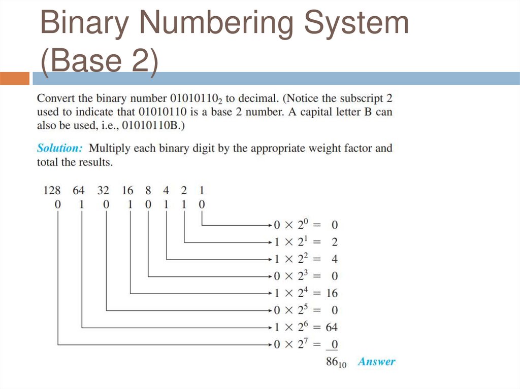
Binary Numbering System(Base 2)
13.
Binary Numbering System(Base 2)
14.
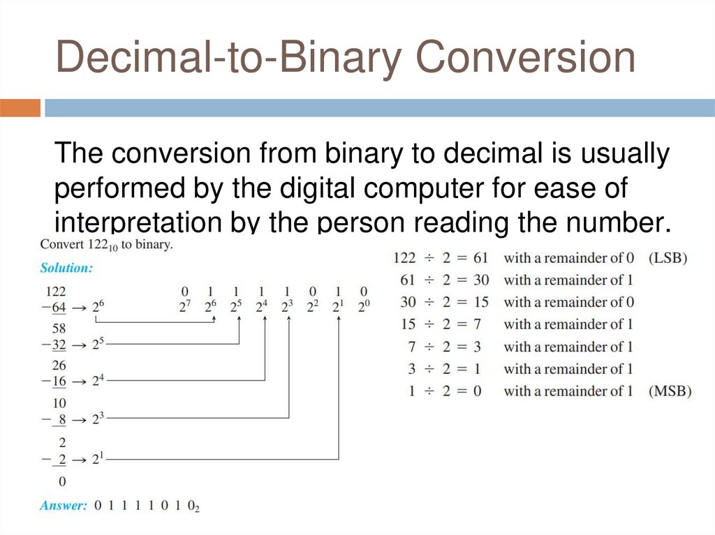
Decimal-to-Binary ConversionThe conversion from binary to decimal is usually
performed by the digital computer for ease of
interpretation by the person reading the number.
15.
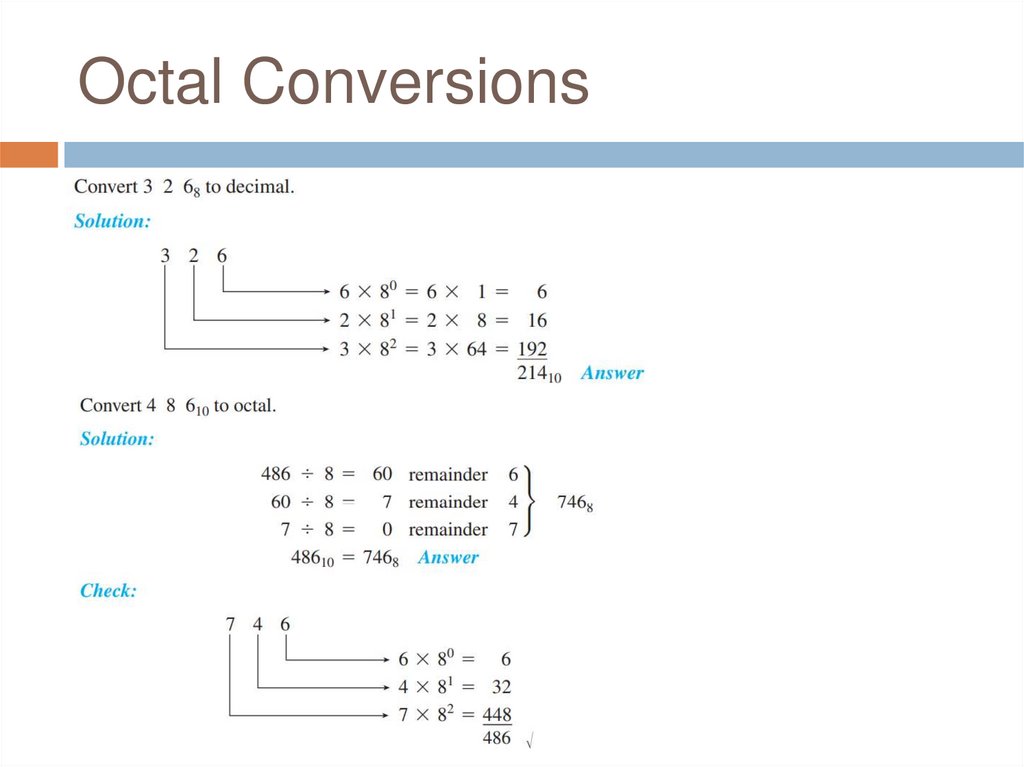
Octal Numbering System (Base8)
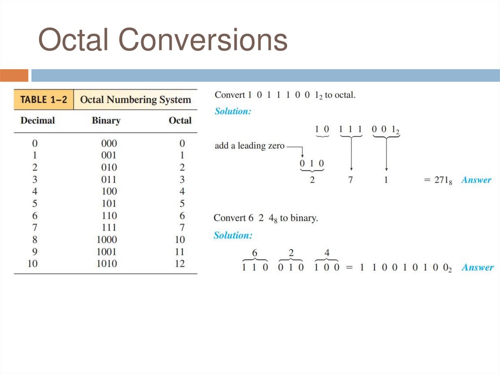
The octal numbering system is a method of
grouping binary numbers in groups of three. The
eight allowable digits are 0, 1, 2, 3, 4, 5, 6, and
7.
The octal numbering system is used by
manufacturers of computers that utilize 3-bit
codes to indicate instructions or operations to
be performed.
By using the octal representation instead of
binary, the user can simplify the task of entering
or reading computer instructions and thus save
16.
Octal Conversions17.
Octal Conversions18.
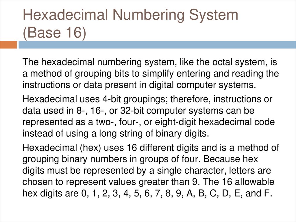
Hexadecimal Numbering System(Base 16)
The hexadecimal numbering system, like the octal system, is
a method of grouping bits to simplify entering and reading the
instructions or data present in digital computer systems.
Hexadecimal uses 4-bit groupings; therefore, instructions or
data used in 8-, 16-, or 32-bit computer systems can be
represented as a two-, four-, or eight-digit hexadecimal code
instead of using a long string of binary digits.
Hexadecimal (hex) uses 16 different digits and is a method of
grouping binary numbers in groups of four. Because hex
digits must be represented by a single character, letters are
chosen to represent values greater than 9. The 16 allowable
hex digits are 0, 1, 2, 3, 4, 5, 6, 7, 8, 9, A, B, C, D, E, and F.
19.
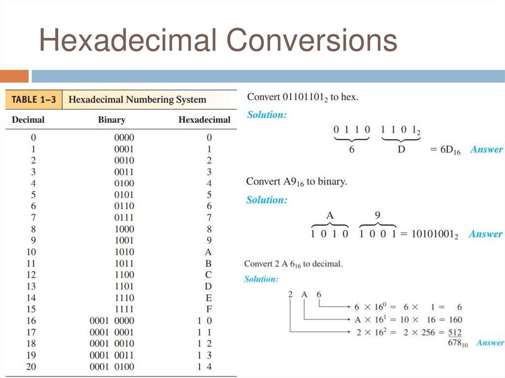
Hexadecimal Conversions20.
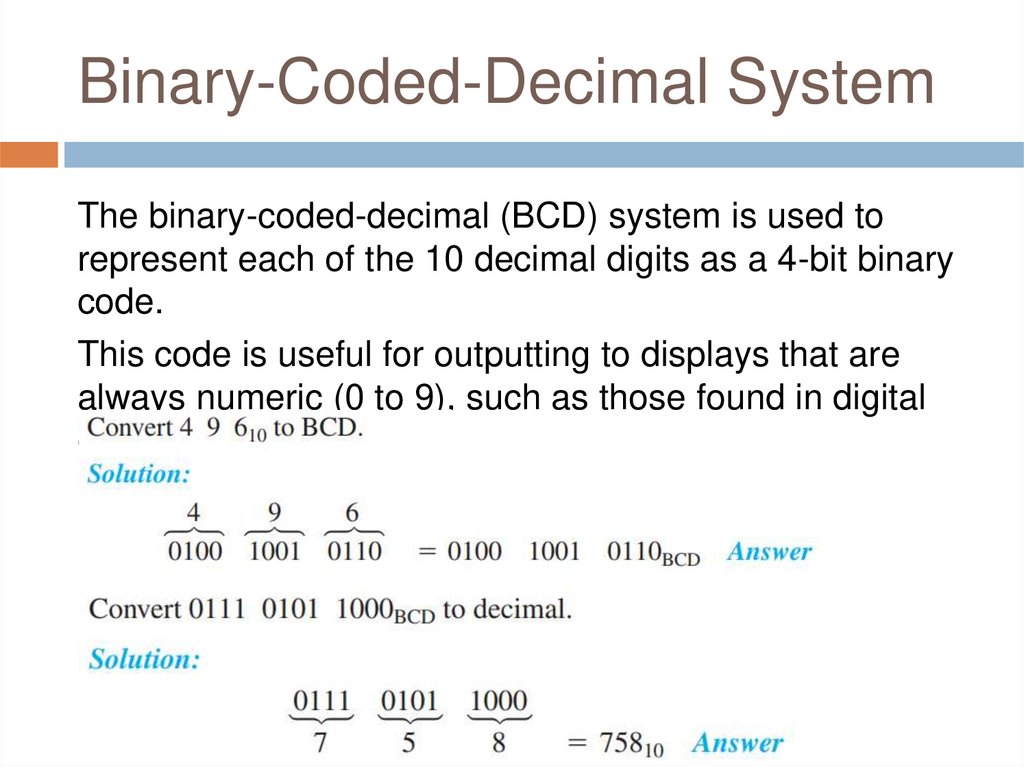
Binary-Coded-Decimal SystemThe binary-coded-decimal (BCD) system is used to
represent each of the 10 decimal digits as a 4-bit binary
code.
This code is useful for outputting to displays that are
always numeric (0 to 9), such as those found in digital
clocks or digital voltmeters.
21.
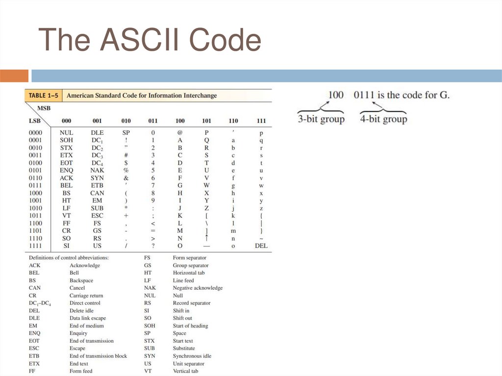
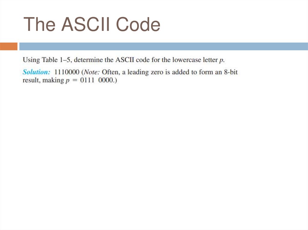
The ASCII Code22.
The ASCII Code23.
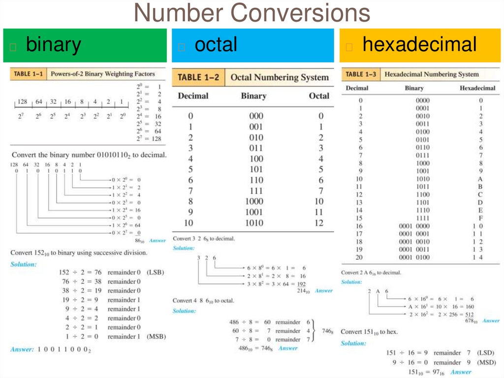
Number Conversions◻
binary
◻
octal
◻
hexadecimal
24.
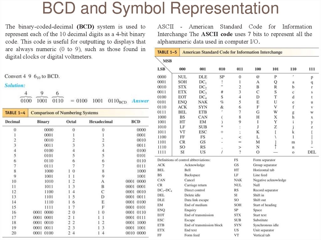
BCD and Symbol RepresentationThe binary-coded-decimal (BCD) system is used to
represent each of the 10 decimal digits as a 4-bit binary
code. This code is useful for outputting to displays that
are always numeric (0 to 9), such as those found in
digital clocks or digital voltmeters.
ASCII - American Standard Code for Information
Interchange The ASCII code uses 7 bits to represent all the
alphanumeric data used in computer I/O.
25.
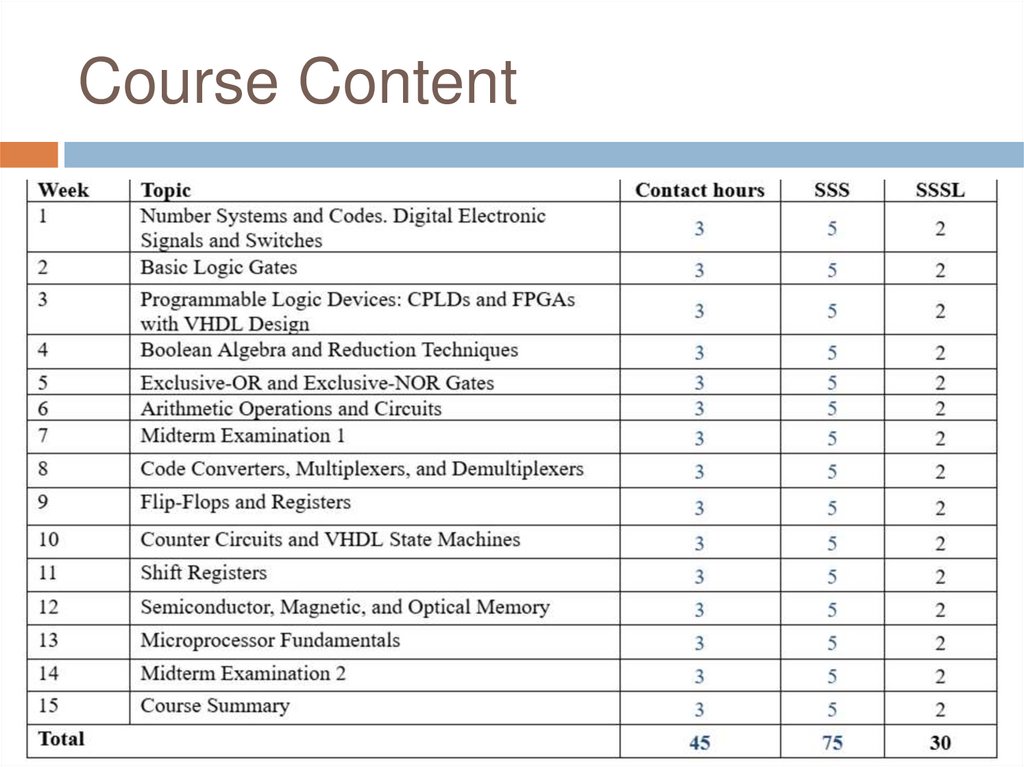
Course Content26.
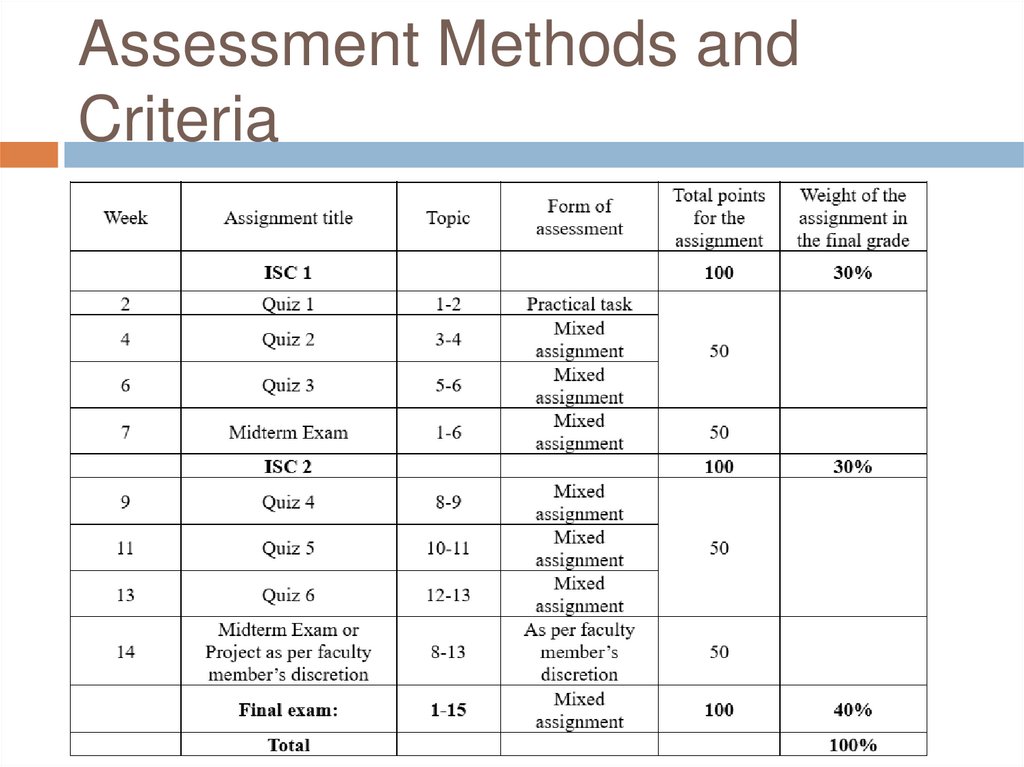
Assessment Methods andCriteria
27.
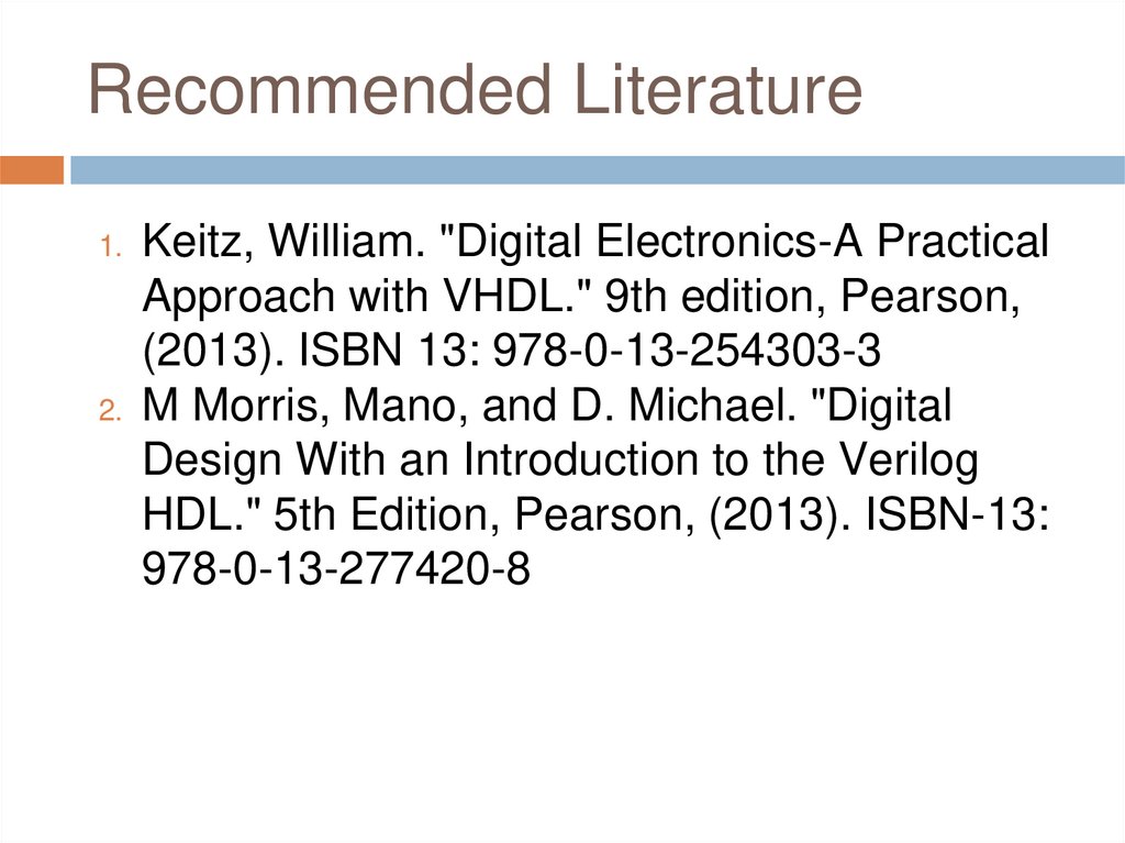
Recommended Literature1. Keitz, William. "Digital Electronics-A Practical
Approach with VHDL." 9th edition, Pearson,
(2013). ISBN 13: 978-0-13-254303-3
2. M Morris, Mano, and D. Michael. "Digital
Design With an Introduction to the Verilog
HDL." 5th Edition, Pearson, (2013). ISBN-13:
978-0-13-277420-8
28.
Softwares◻
◻
NI Multisim — a desktop application for
creating electronic circuits and simulation.
Quartus II — software for designing
programmable logic devices.
29.
Digital Electronic Signals andSwitches
30.
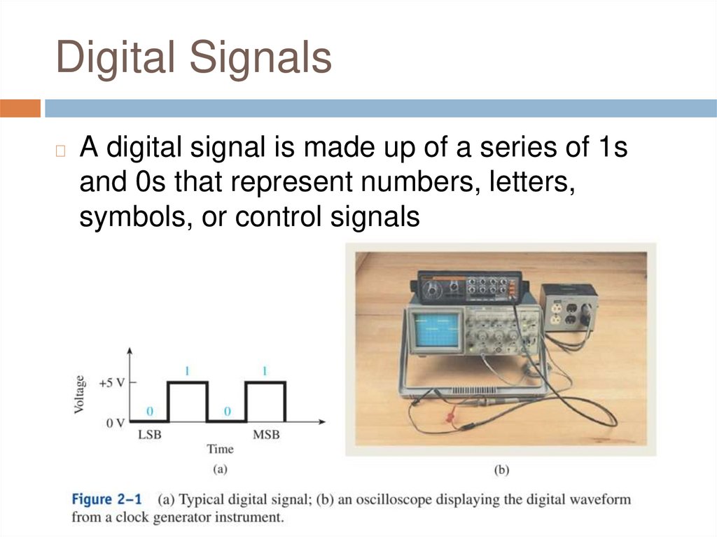
Digital Signals◻
A digital signal is made up of a series of 1s
and 0s that represent numbers, letters,
symbols, or control signals
31.
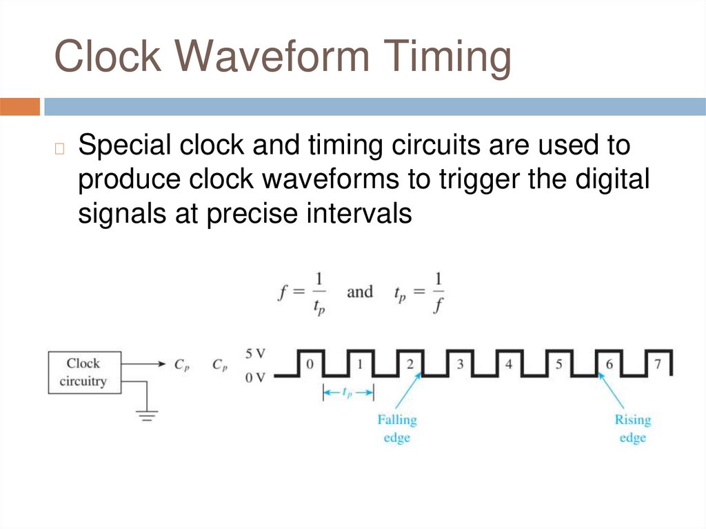
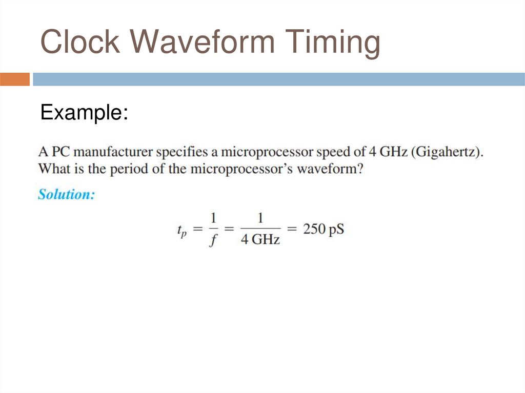
Clock Waveform Timing◻
Special clock and timing circuits are used to
produce clock waveforms to trigger the digital
signals at precise intervals
32.
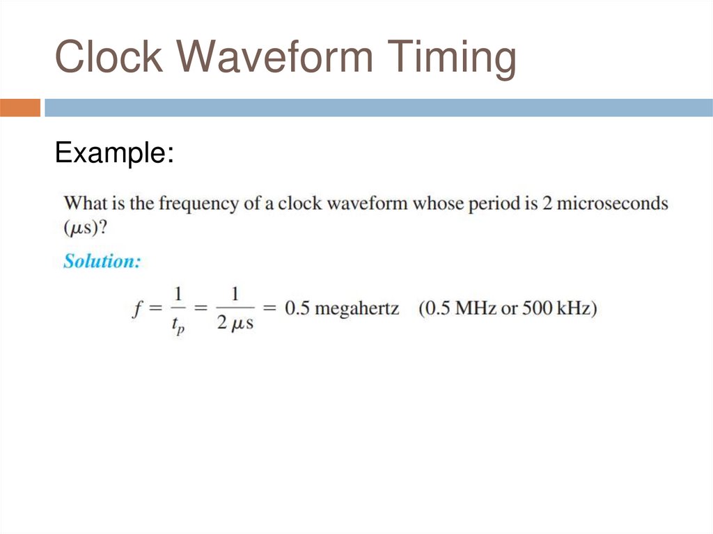
Clock Waveform TimingExample:
33.
Clock Waveform TimingExample:
34.
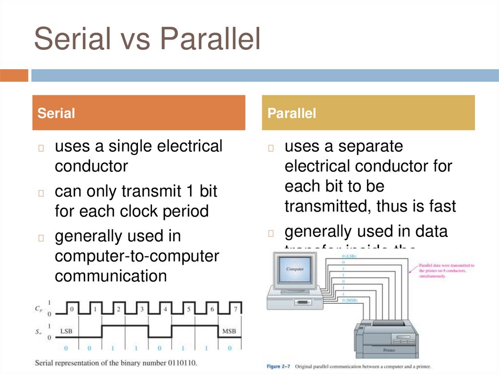
Serial vs ParallelSerial
Parallel
uses a single electrical
conductor
◻ can only transmit 1 bit
for each clock period
◻ generally used in
computer-to-computer
communication
◻
◻
uses a separate
electrical conductor for
each bit to be
transmitted, thus is fast
◻ generally used in data
transfer inside the
computer
35.
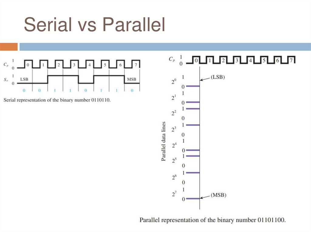
Serial vs Parallel36.
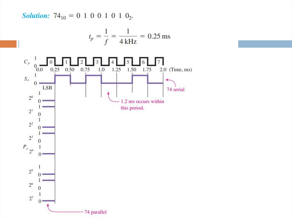
Serial vs ParallelExample:
37.
38.
Review Questions1.
2.
3.
Why is ASCII code required by digital
computer systems?
What is the relationship between clock
frequency and clock period?
What advantage does parallel have over serial
in the transmission of digital signals?
39.
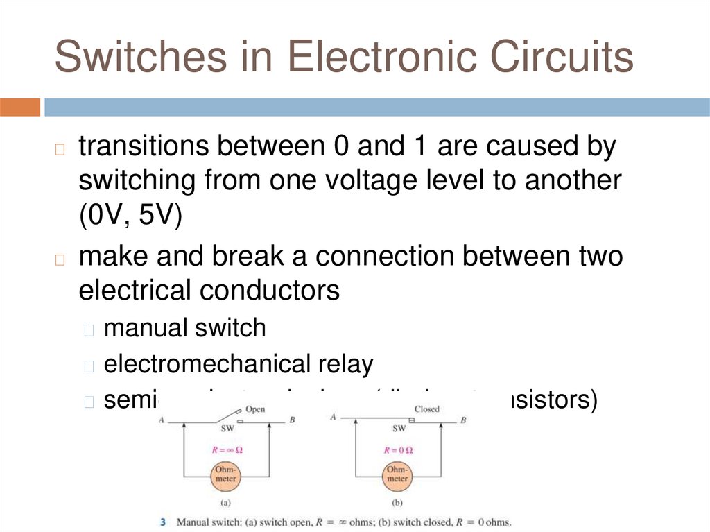
Switches in Electronic Circuitstransitions between 0 and 1 are caused by
switching from one voltage level to another
(0V, 5V)
◻ make and break a connection between two
electrical conductors
◻
◻ manual switch
◻ electromechanical relay
◻ semiconductor devices (diodes, transistors)
40.
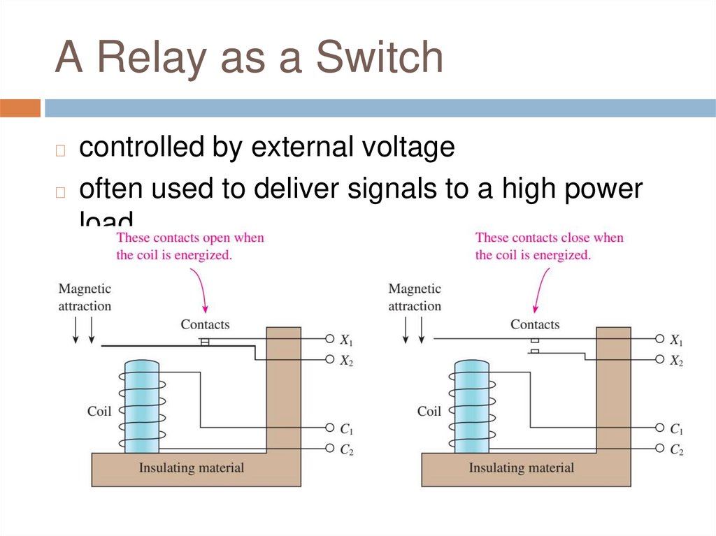
A Relay as a Switchcontrolled by external voltage
◻ often used to deliver signals to a high power
load
◻
41.
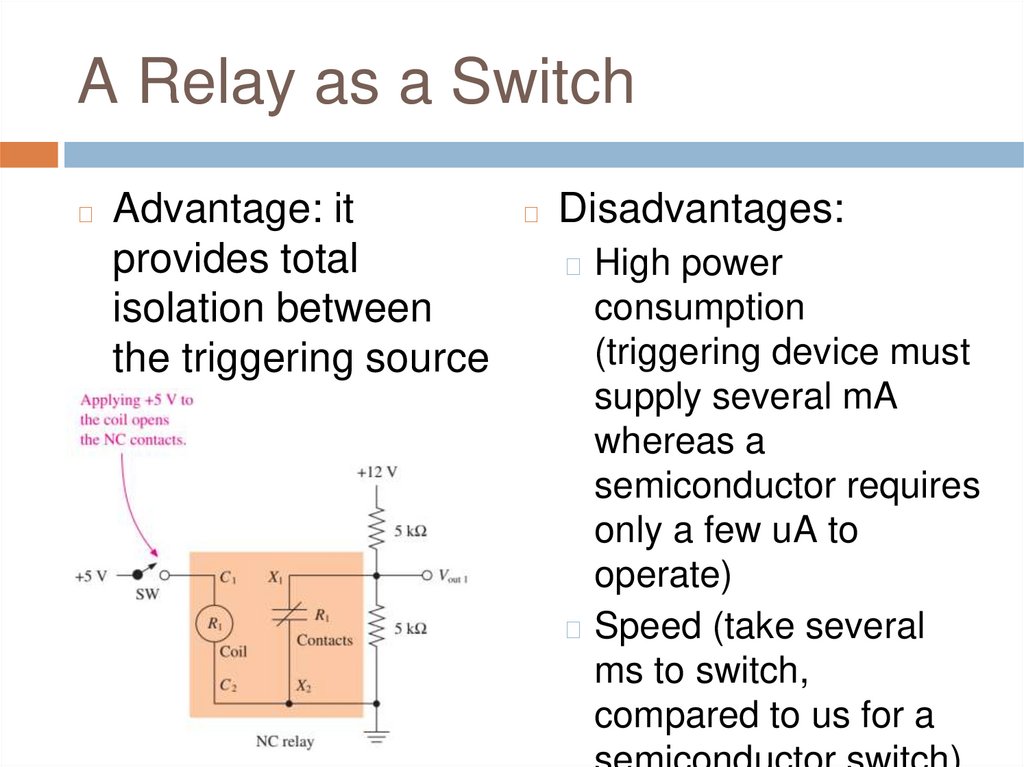
A Relay as a Switch◻
Advantage: it
provides total
isolation between
the triggering source
and the output
◻
Disadvantages:
◻ High power
consumption
(triggering device must
supply several mA
whereas a
semiconductor requires
only a few uA to
operate)
◻ Speed (take several
ms to switch,
compared to us for a
42.
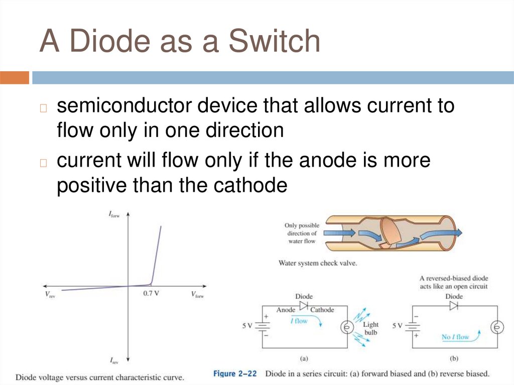
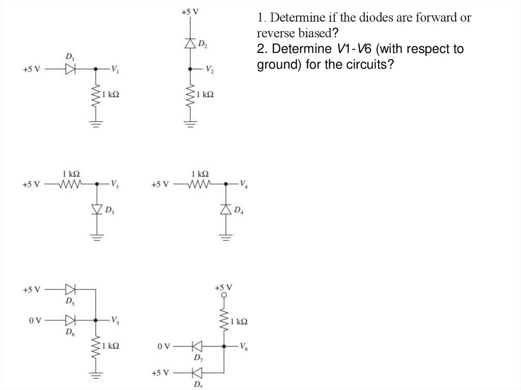
A Diode as a Switchsemiconductor device that allows current to
flow only in one direction
◻ current will flow only if the anode is more
positive than the cathode
◻
43.
1. Determine if the diodes are forward orreverse biased?
2. Determine V1-V6 (with respect to
ground) for the circuits?
44.
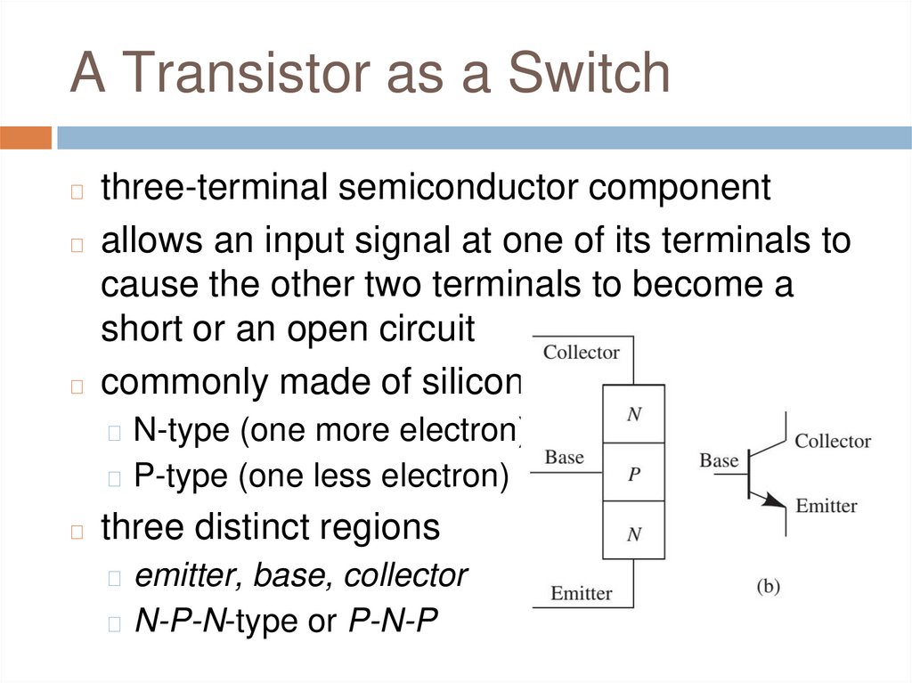
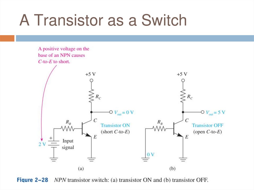
A Transistor as a Switchthree-terminal semiconductor component
◻ allows an input signal at one of its terminals to
cause the other two terminals to become a
short or an open circuit
◻ commonly made of silicon
◻
◻ N-type (one more electron)
◻ P-type (one less electron)
◻
three distinct regions
◻ emitter, base, collector
◻ N-P-N-type or P-N-P
45.
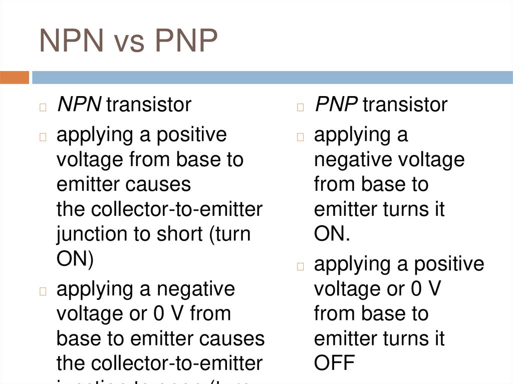
NPN vs PNPNPN transistor
◻ applying a positive
voltage from base to
emitter causes
the collector-to-emitter
junction to short (turn
ON)
◻ applying a negative
voltage or 0 V from
base to emitter causes
the collector-to-emitter
◻
PNP transistor
◻ applying a
negative voltage
from base to
emitter turns it
ON.
◻ applying a positive
voltage or 0 V
from base to
emitter turns it
OFF
◻
46.
A Transistor as a Switch47.
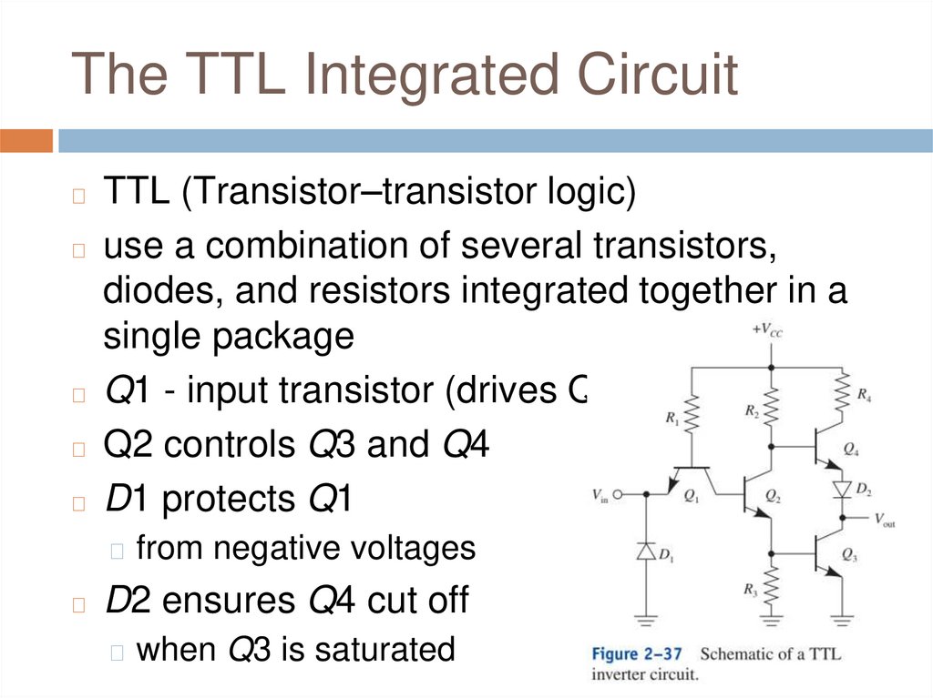
The TTL Integrated CircuitTTL (Transistor–transistor logic)
◻ use a combination of several transistors,
diodes, and resistors integrated together in a
single package
◻ Q1 - input transistor (drives Q2)
◻ Q2 controls Q3 and Q4
◻ D1 protects Q1
◻
◻ from negative voltages
◻
D2 ensures Q4 cut off
◻ when Q3 is saturated
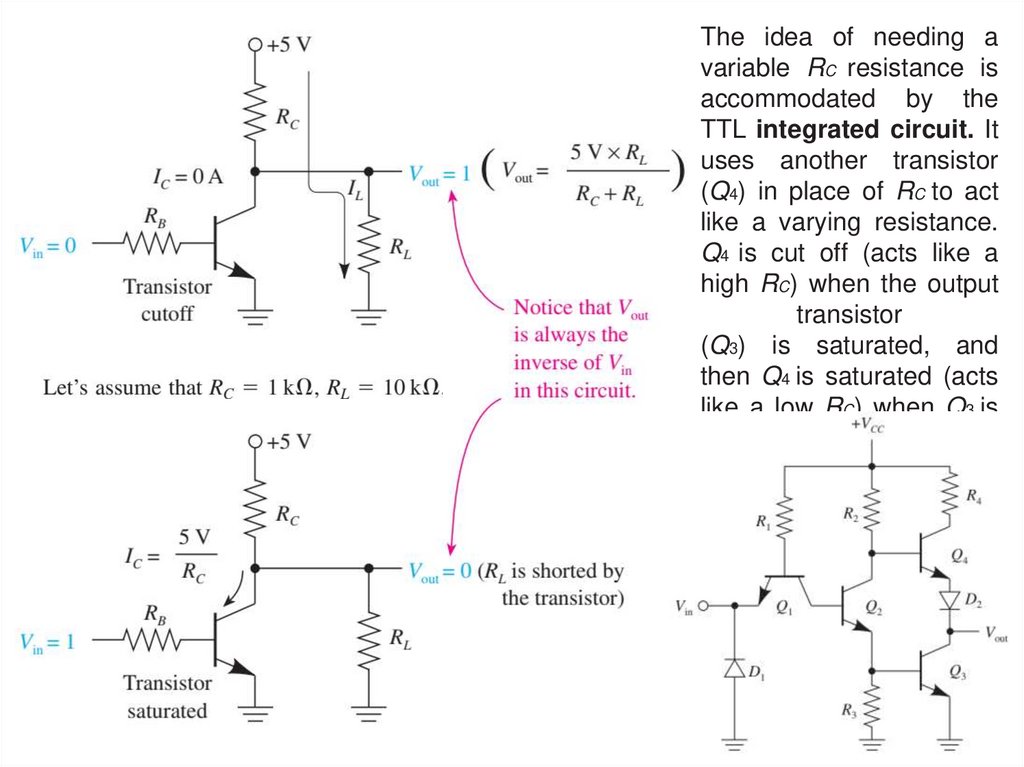
48.
The idea of needing avariable RC resistance is
accommodated by the
TTL integrated circuit. It
uses another transistor
(Q4) in place of RC to act
like a varying resistance.
Q4 is cut off (acts like a
high RC) when the output
transistor
(Q3) is saturated, and
then Q4 is saturated (acts
like a low RC) when Q3 is
cut
off.
49.
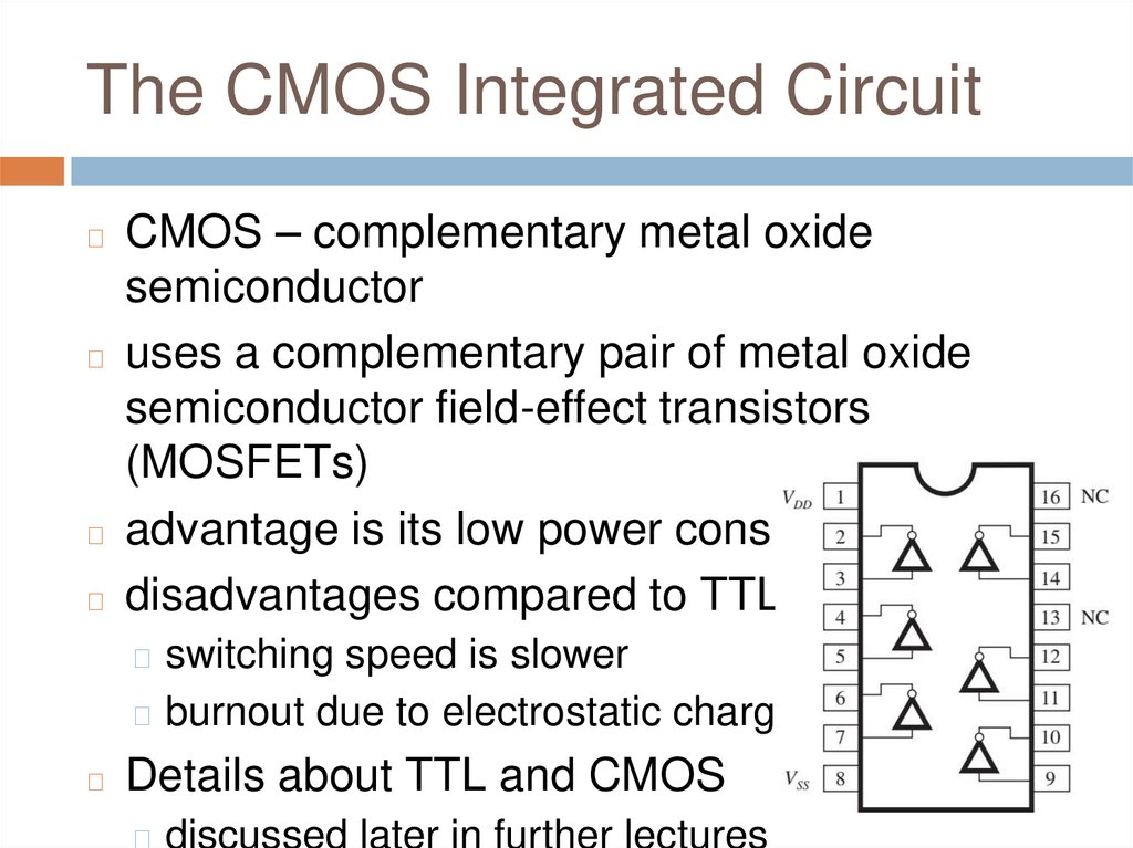
The CMOS Integrated CircuitCMOS – complementary metal oxide
semiconductor
◻ uses a complementary pair of metal oxide
semiconductor field-effect transistors
(MOSFETs)
◻ advantage is its low power consumption
◻ disadvantages compared to TTL:
◻
◻ switching speed is slower
◻ burnout due to electrostatic charges
◻
Details about TTL and CMOS
◻ discussed later in further lectures
50.
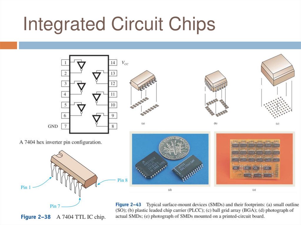
Integrated Circuit Chips51.
Review Questions1.
2.
3.
How does a normally open relay differ from a
normally closed relay?
To forward bias a diode, the anode is made
more ___________ (positive/negative) than
the cathode.
To turn ON an NPN transistor, a ___________
(positive/negative) voltage is applied to the
base.
52.
Q&AAny Questions?