


 electronics
Similar presentations:

")


")


Digital Electronics course. Ilyassov Baurzhan, PhD, associate professor, department of intelligent systems and cybersecurity
1.
Digital Electronics courseIlyassov Baurzhan, PhD, associate professor,
department of intelligent systems and cybersecurity.
2.
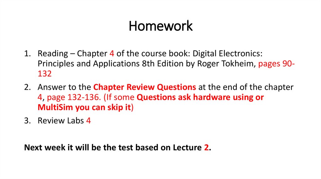
Homework1. Reading – Chapter 4 of the course book: Digital Electronics:
Principles and Applications 8th Edition by Roger Tokheim, pages 90132
2. Answer to the Chapter Review Questions at the end of the chapter
4, page 132-136. (If some Questions ask hardware using or
MultiSim you can skip it)
3. Review Labs 4
Next week it will be the test based on Lecture 2.
3.
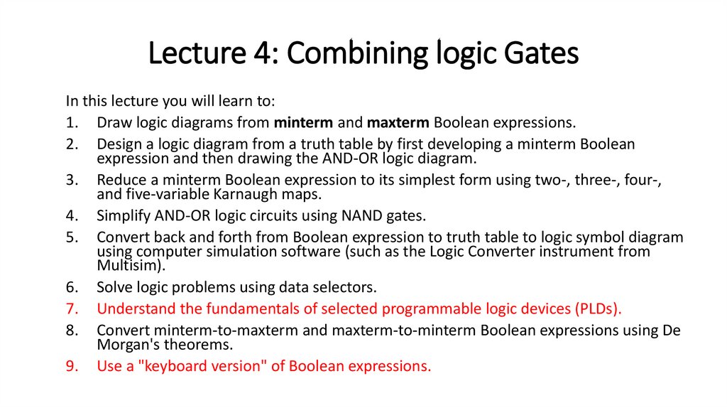
Lecture 4: Combining logic GatesIn this lecture you will learn to:
1. Draw logic diagrams from minterm and maxterm Boolean expressions.
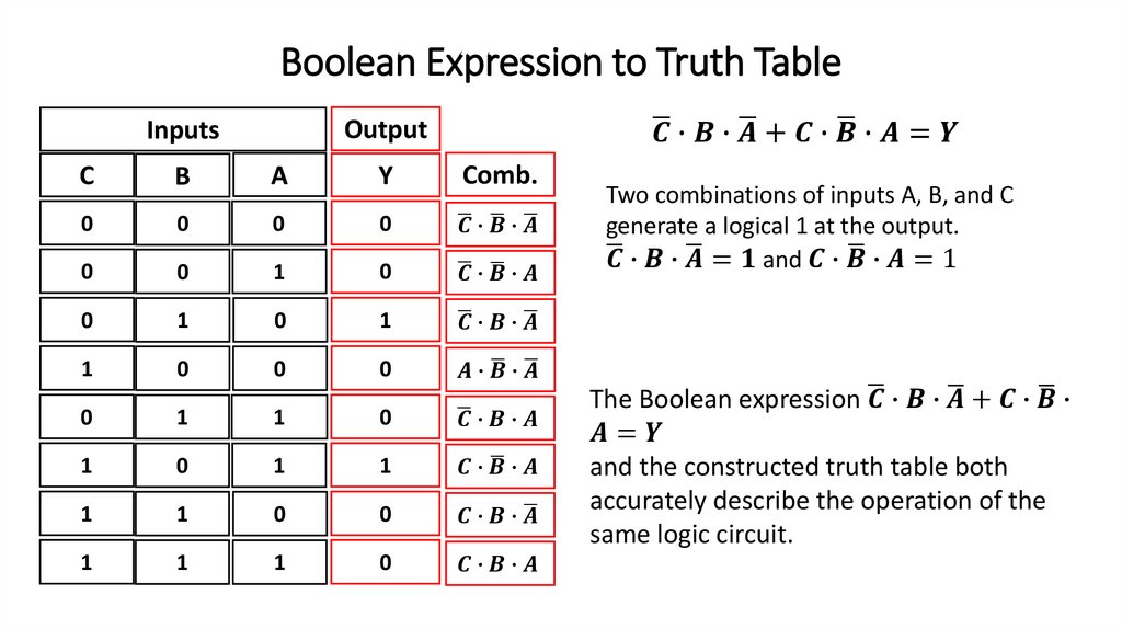
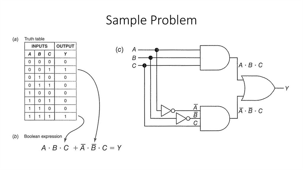
2. Design a logic diagram from a truth table by first developing a minterm Boolean
expression and then drawing the AND-OR logic diagram.
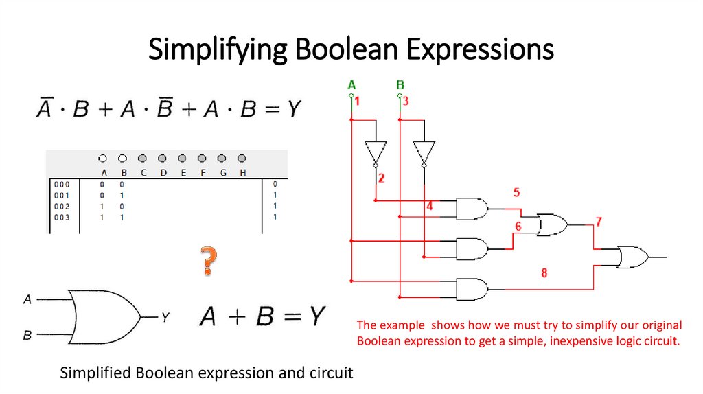
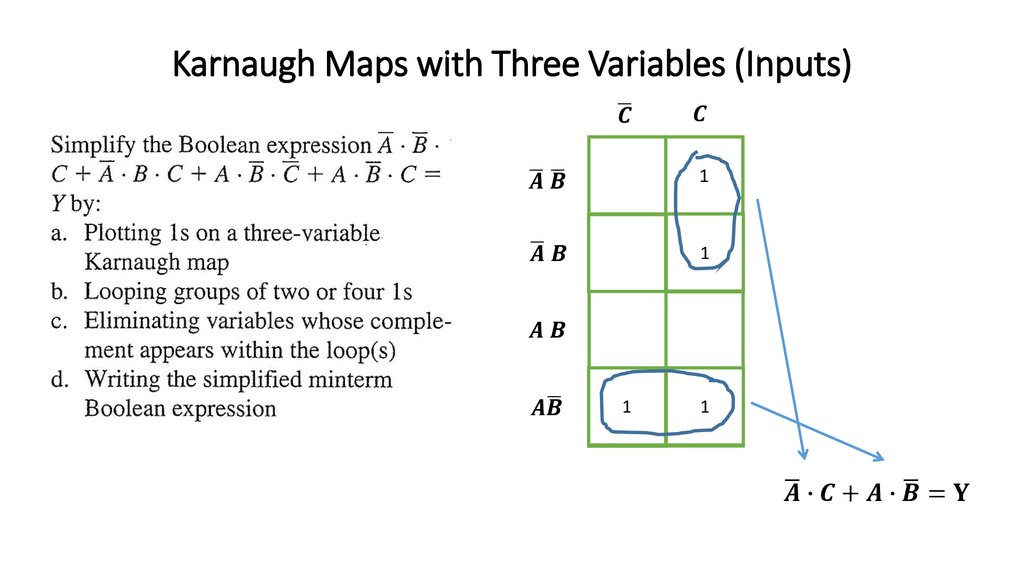
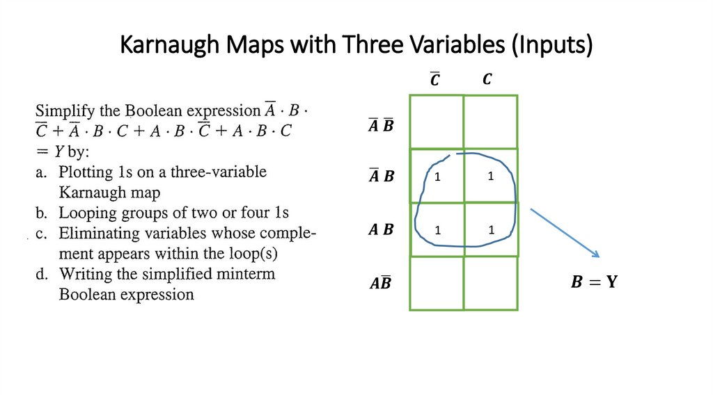
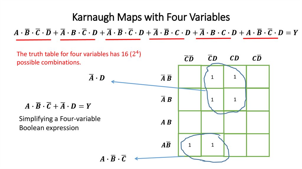
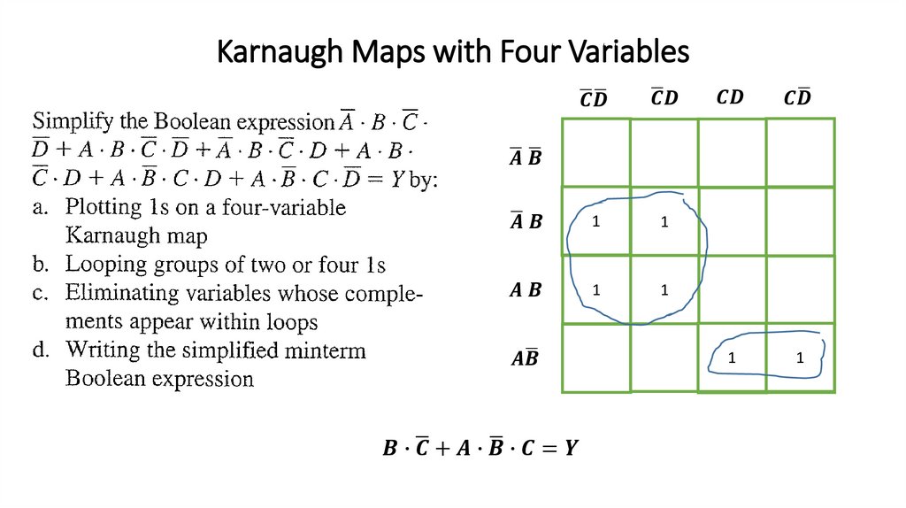
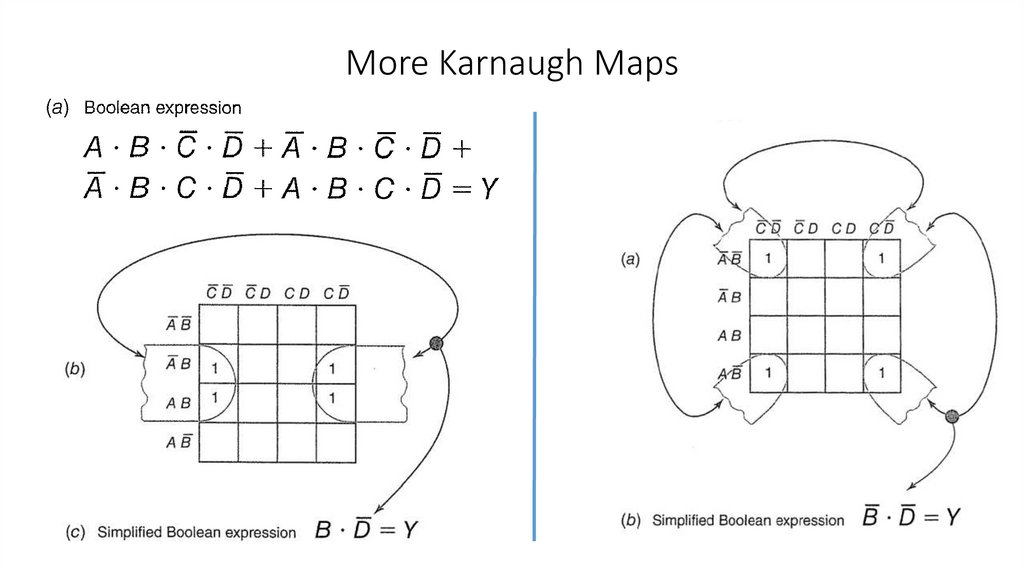
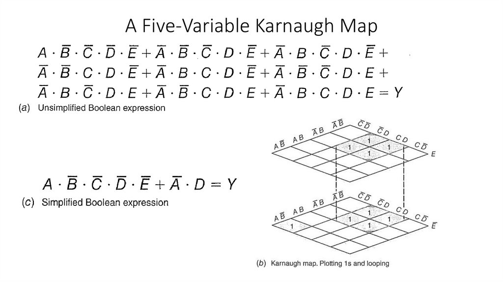
3. Reduce a minterm Boolean expression to its simplest form using two-, three-, four-,
and five-variable Karnaugh maps.
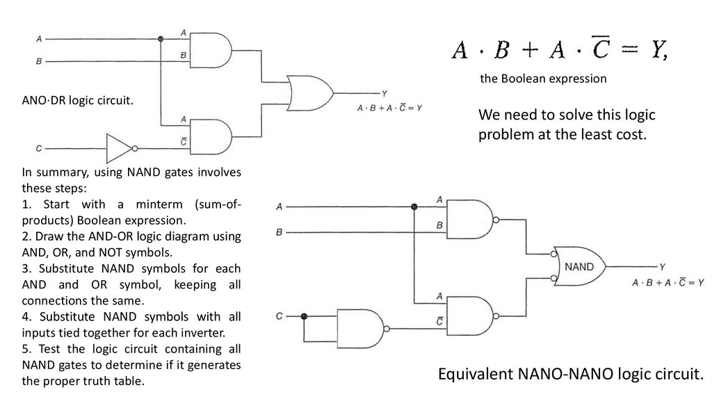
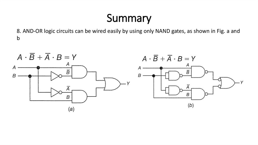
4. Simplify AND-OR logic circuits using NAND gates.
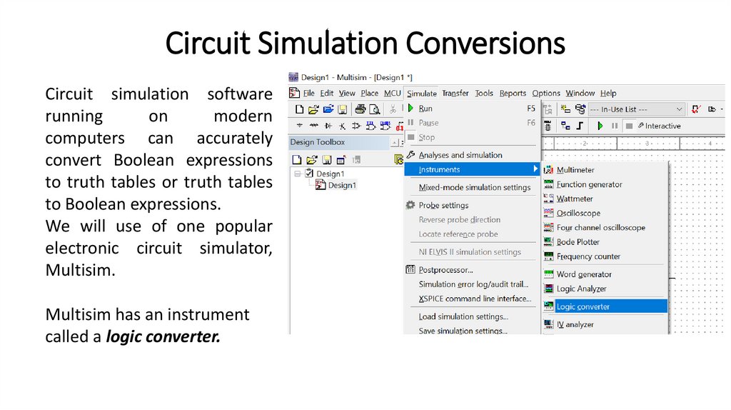
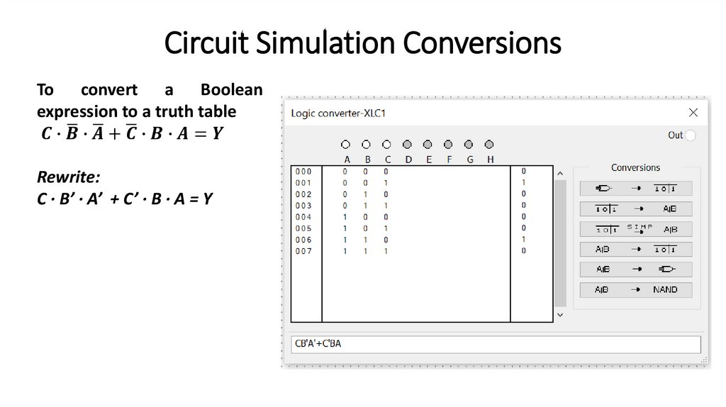
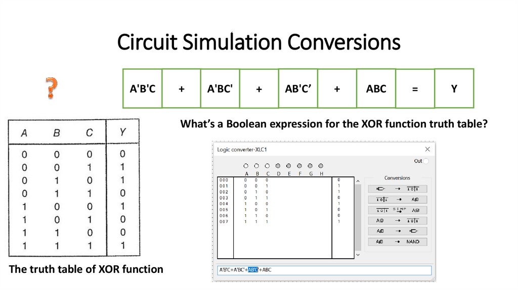
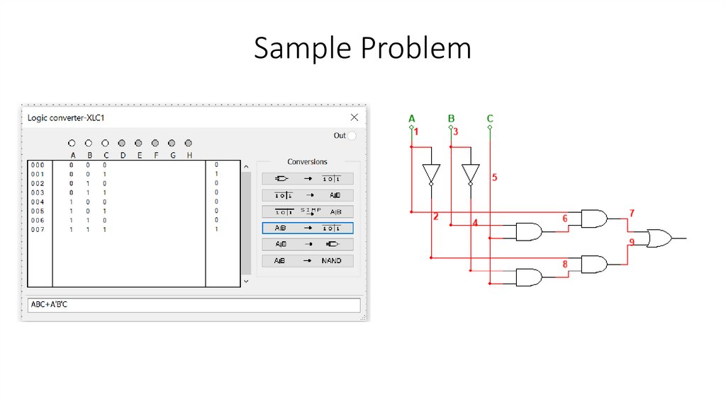
5. Convert back and forth from Boolean expression to truth table to logic symbol diagram
using computer simulation software (such as the Logic Converter instrument from
Multisim).
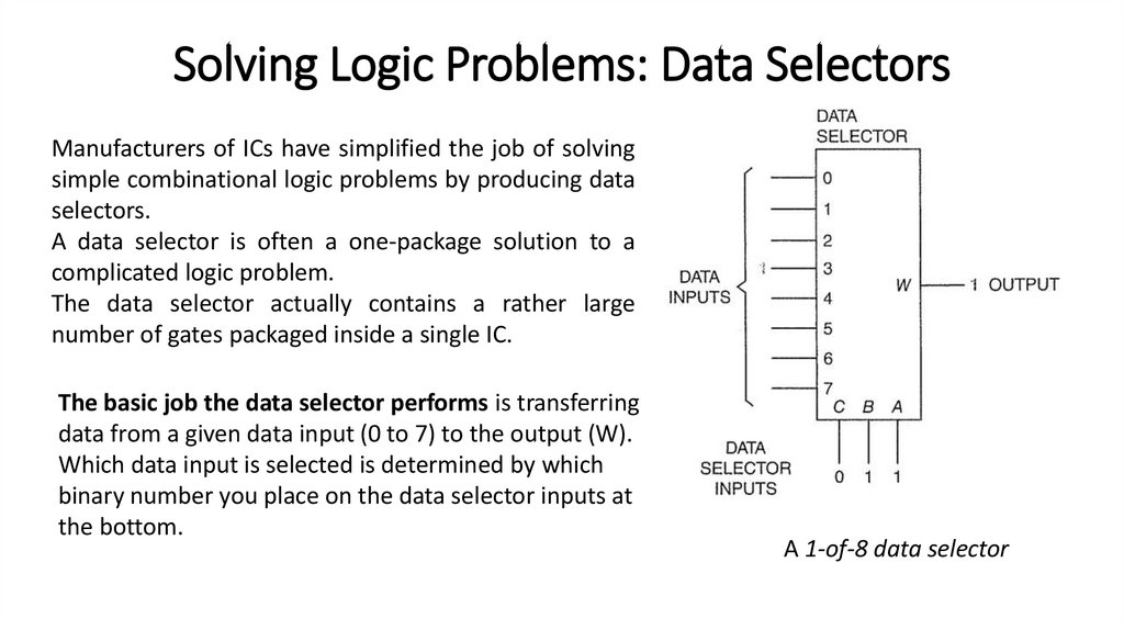
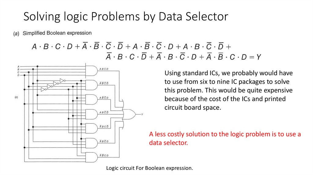
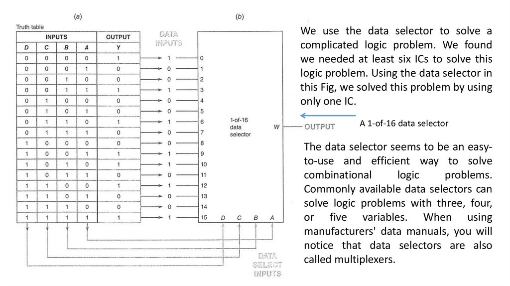
6. Solve logic problems using data selectors.
7. Understand the fundamentals of selected programmable logic devices (PLDs).
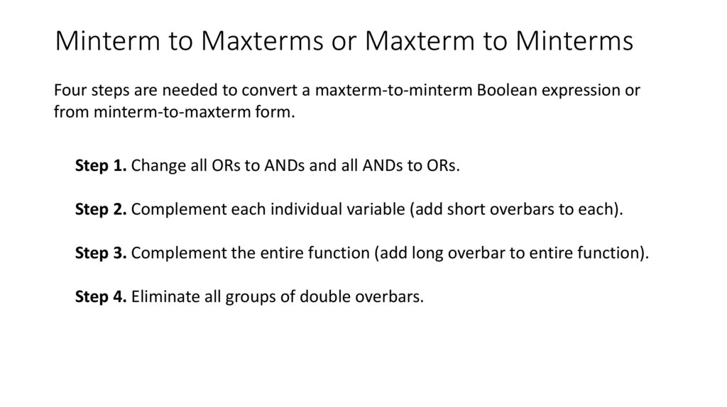
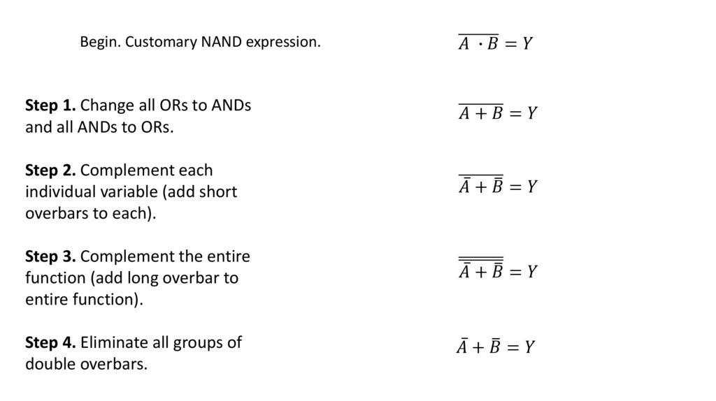
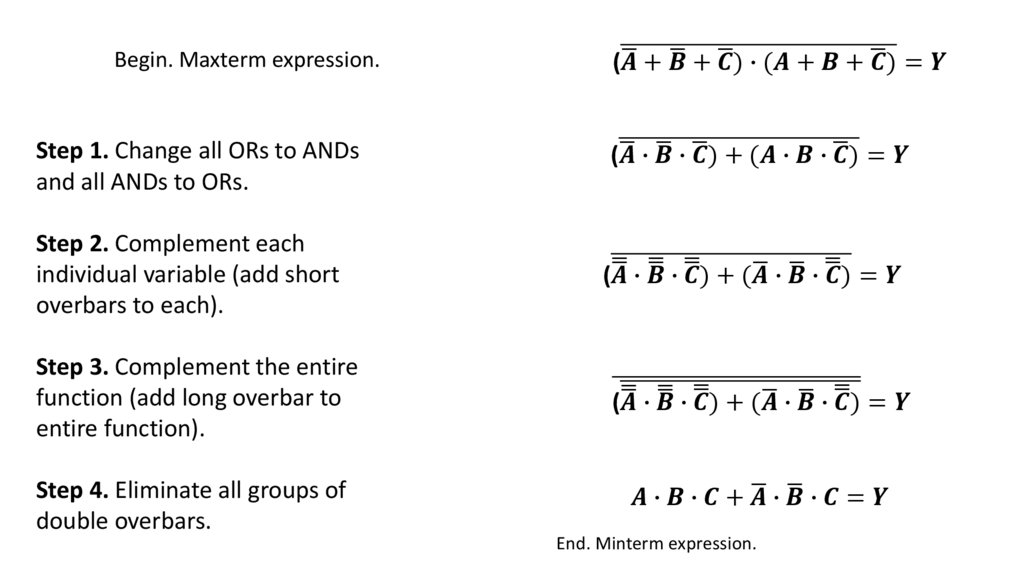
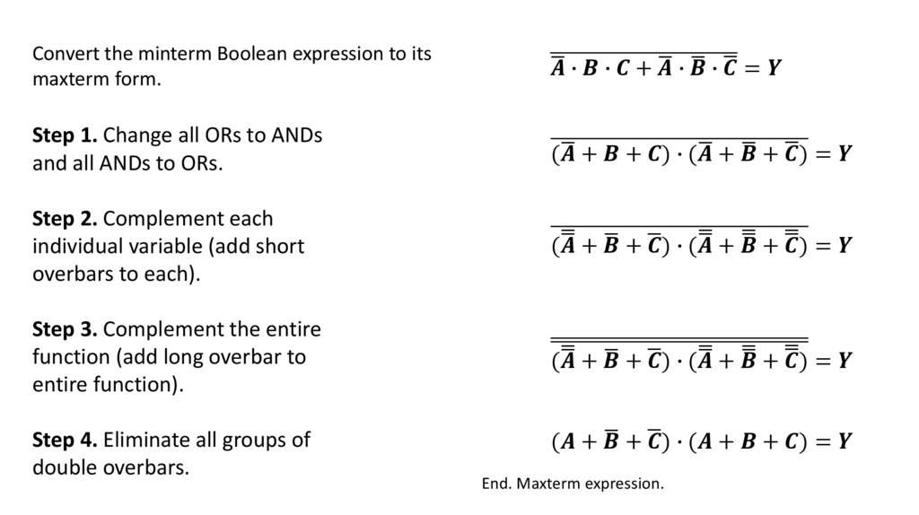
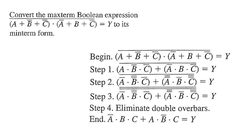
8. Convert minterm-to-maxterm and maxterm-to-minterm Boolean expressions using De
Morgan's theorems.
9. Use a "keyboard version" of Boolean expressions.
4.
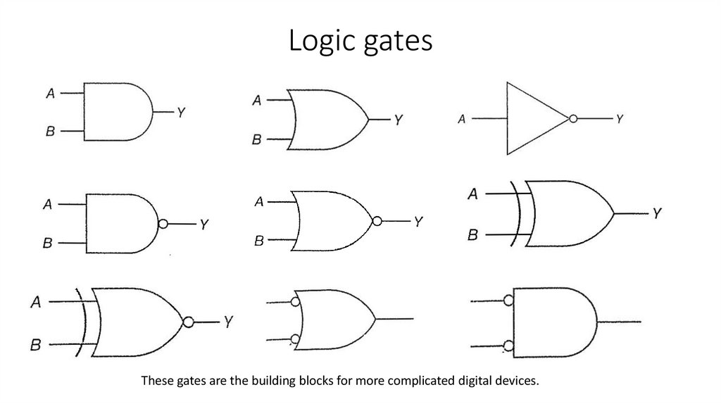
Logic gatesThese gates are the building blocks for more complicated digital devices.
5.
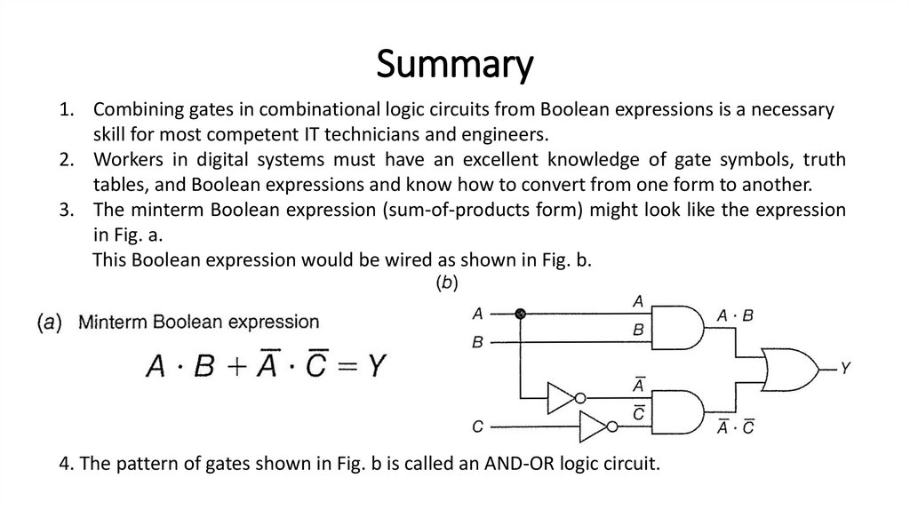
Combinational logicIn this lecture we will use our knowledge of gate symbols, truth tables, and Boolean
expressions to solve real-world problems in electronics.
You will be connecting gates to form what engineers refer to as combinational logic
circuits.
Combinational logic is an interconnection of logic gates to generate a specified logic
function where the inputs result in an immediate output, having no memory or
storage capabilities.
Digital circuits that have a memory or storage capability are called sequential logic
circuits.
6.
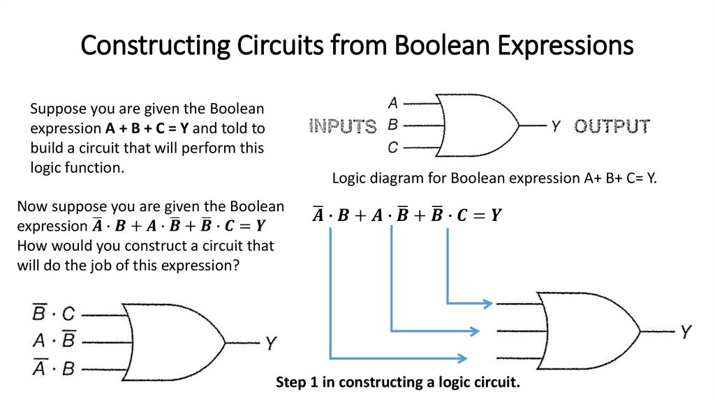
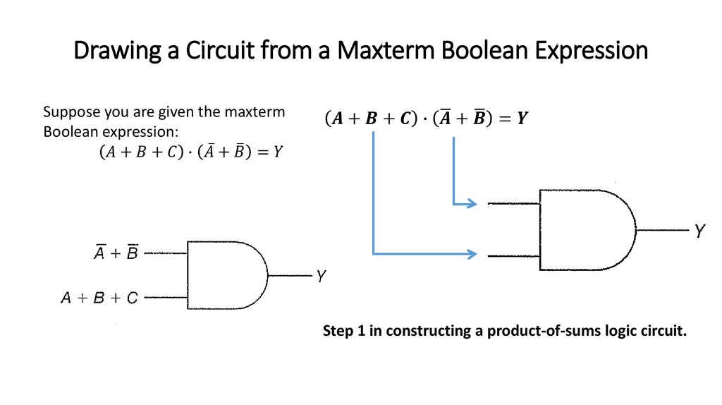
Constructing Circuits from Boolean ExpressionsSuppose you are given the Boolean
expression A + B + C = Y and told to
build a circuit that will perform this
logic function.
Logic diagram for Boolean expression A+ B+ C= Y.
Now suppose you are given the Boolean
ഥ∙